Creating 3D Game Art for the iPhone with Unity Part 4 ppt
Bạn đang xem bản rút gọn của tài liệu. Xem và tải ngay bản đầy đủ của tài liệu tại đây (2.47 MB, 28 trang )
a level. The whole manner in which you construct the level can bear great
importance on
the performance. In Chapter 2, we looked at the creation of
Tater and the process was fairly straightforward. We discussed determining
a vertex budget, and from there, we modeled and UV mapped the
character
to ad
here to that budget. However, with an entire level, there’s much
more
to consider. Dep
ending on your game, a level can be rather large,
and
you shouldn’t
just build the entire level into one mesh and send that
off
to the GPU. W
ell, that is to say, if you’re concerned about performance
you wouldn’t.
When you look at designing a level, you need to think about both the tech
-
nical and artistic aspects. For instance, on the artistic side, you need to think
about how a level lends itself t
o the overall story of the game. You need to
think about how each level will entice the player with something new and
engaging, but also increase in difficulty to keep the player interested. You
need to make sure that each level builds upon each other and supports to
progress the overall story of the game.
On the technical side, you need to be constantly focused on performance.
This brings us to the constant struggle we face as game developers, which is
the balancing of performance artistic vision. Sure, you can throw everything
but the kitchen sink into your level, and although it make look fantastic, it
unfortunately doesn’t run beyond 12 FPS. This would result in a failed game,
as it doesn’t play well.
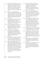
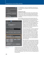
FIG 4.1 This Is the Level We’ll Discuss Throughout the Book.
66
Creating 3D Game Art for the iPhone with Unity
Over the next several sections, we’ll be taking a look at how to balance the art
and technical limitations in order to build high-quality and optimized content.
Creating a Style
Although the focus of the book is on the technical aspects of building content,
I felt it would be important to talk a bit about style. The style of your game
should speak to the audience and lend itself to the experience you’re trying
to create for the player. As I mentioned, in this chapter, we’re going to look at
building a level from Tater’s world. Before any content is created, I had already
written out an entire synapse for my Tater character. I worked out his look,
personality, and environment. I then hired Warner McGee, a talented character
designer, to create the illustration and polish up Tater’s overall style. Having a
strong understanding of the world you want to create is key to visualizing a
style for your level and characters. For instance, Tater is a bit of a country bump-
kin and analyzing his personality and traits helped me to visualize the type of
environment that would fit his persona. For the book, I wanted to create a level
that would showcase the process behind creating optimized content while also
adhering to the overall style and design of “Dead Bang” game property I have
been working on. The level we’ll be creating in the book is that of a trash yard.
It’s old and dirty and lends itself to Tater’s style. Always remember that the lev-
els you create in your games are just as much of a vital character asset as your
main hero character. The next step was to sketch out the layout of the level so
that when the time comes for actual modeling, I’ll have a diagram to follow. All
of the trial and error of the design and layout are worked out on paper first.
Always remember that the levels you create in your games are just as
much of a vital character asset as your main hero character.
What Can Reasonably Be Accomplished?
We previously discussed the balancing act behind technical limitations and
artistic creation. When designing a style for your content, it’s always good to
start with the question, “What can reasonably be accomplished?” You need to
consider what can be accomplished within either your self-imposed or project
deadlines. You will need to decide what artistic avenues you want to explore
in your game are actually possible to implement while maintaining a solid
frame rate. Again, we need to balance the artistic to the technical. Remember,
it’s not a matter of compromising artistic vision, but a matter of finding the
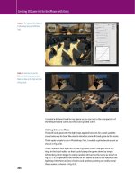
best solution to accommodate your style. For example, I had an idea for the
trash yard for giving a hint of increased depth by adding some areas closed off
by chain-link fences as shown in Fig. 4.2.
Always address the style issues up-front; in the design phase of your
level by asking the important question, “Can this be reasonably
accomplished?”
The chain-link fence areas would also lend itself well to the trash yard theme;
ho
wever, this would involve the use of an alpha transparency shader. I was a
67
Creating Game Objects Using modo
bit cautious of this because I know that the iPad and iPhone 4 can suffer from
fill-rate issues, especially when filling the screen with a transparent polygon.
So, I asked the question, “Can this reasonably be accomplished?” Later in this
chapter, we’ll talk about how I tested this scenario, but for now, you can see
the situations like this you need to address up front. It’s much easier to decide
to drop the fences in the design phase and go another route versus having to
scrap a model and start over due to performance issues. Always address the
style issues up-front, in the design phase of your level by asking the important
question, “Can this be reasonably accomplished?”
Breaking Down into Sections
So, we’ve talked about style, and in this section, we’ll start to really address the
design of the level in terms of optimization. It’s always a good idea to break
your level down into sections as shown in Fig. 4.3.
There are several advantages to breaking the level geometry down into
sections, which I’ve organized into three categories, Puzzle Building, Lazy
Loading, and Optimize Batching.
Puzzle Building
Breaking the level design into sections give us the opportunity to create
seamless tiles or puzzle-like pieces of geometry that can be used to build a
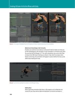
level in any number of configurations as shown in Fig. 4.4.
FIG 4.2 Fence Areas Are Closed off to Player but Give the Illusion There’s More to the Level.
68
Creating 3D Game Art for the iPhone with Unity
Now, for the level showcased in this book, I didn’t go as far with the level
tiles as to make them totally seamless, as it wasn’t necessary for my overall
design, but it’s an important technique to mention. However, the
sections of
lev
els I did create can be configured somewhat differently than my origi-
nal layout. With Unity iOS, we now have the ability to work with mesh tiles
from within the application. By using the new Vertex Snapping feature, we
can simply and accurately snap tiles together by holding down the V key,
hovering the mouse pointer over a desired vertex, and left-click and drag-
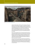
ging to snap the mesh to a vertex on another tile as shown in Fig. 4.5. Vertex
Snapping in Unity iOS ensures that both meshes are “snapped” precisely
together and can be used to quickly connect several mesh tiles to create a
level within the application.
As you can see, creating mesh tiles and using Vertex Snapping in Unity iOS is
a very effective way to build a level. We’ll discuss the entire process later in the
“Building on the Grid” section.
Lazy Loading
Breaking the level down into sections also gives us the ability to optimize
large levels by using what is referred to as lazy loading, which is the proc-
ess of deferring the initialization of an object until it’s absolutely needed.
For instance, let’s say we have a large level broken into four sections. In your
game logic, you can create a methodology for loading one of the next sec-
tions when the player has reached a goal position. With that same token,
you can unload a section once the player has also reached a goal position.
FIG 4.3 Here the Level Is Divided into Sections.
69
Creating Game Objects Using modo
For instance, you could setup a blockade, which controls how much the player
is aloud to backtrack in a level. Once the player has reached a certain position,
you can safely unload the section. Now, discussing the implementation of this
procedure is beyond the scope of this book, but it’s important to understand
the advantages to breaking the level down into sections in terms of load-
ing. For this method, each section is saved as a separate FBX file that can be
loaded when needed. Also, with each section exported as a separate file, you
can implement an asset downloading mechanism to your game so that player
can use In-App purchases.
Optimize Batching and Rendering
As we discussed in Chapter 1, batching is extremely important for optimizing
your game’s performance, and special care needs to be taken to make sure
that your meshes can and will be able to batch. By breaking the level into
sections, you gain two advantages in terms of rendering vertices. First, it will
be easier to stay within the 300-vertex limit that is a restriction of Dynamic
FIG 4.4 The Level Can Be Broken Down into Smaller Tileable Elements.
70
Creating 3D Game Art for the iPhone with Unity
Batching and second; you further optimize the amount of vertices sent to the
GPU in regards to the camera’s view frustum.
Batching Revisited
In Chapter 1, we took a technical look at both Dynamic and Static Batching.
Let’s now take a more practical look at Static Batching as it pertains to creat-
ing a level. I mentioned earlier that creating our level in sections would
further optimize the amount of vertices sent to the GPU. As we mentioned
in Chapter
1, with Static Batching, vertices are stored in an indexed v
ertex
buffer, which contains less data for the CPU to deal with and is thus faster than
Dynamic Batching. However, we then have the caveat of not being able to
transform the vertices. Static Batching creates a shared mesh. These items are
not combined. They remain separate, but all of the vertices are all added to
an indexed vertex buffer, which is the vital aspect of Static Batching in terms
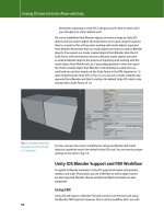
of how you create your objects. Let’s take a look at an example. In Fig.
4.6,
I
combined two sections from a level into one in modo and added a third sec-
tion to the sc
ene in Unity iOS so that we have two meshes to be rendered. You
can also see that the camera’s view is only showing half of the level. Because
I’ve marked all of the meshes to Static and adhered to the rules of creating a
batch, the meshes will be batched into one draw call. However, our job toward
optimization isn’t done. We not only have to think about the draw call, but
the camera view frustum and how it relates to the amount of vertices being
stored in the indexed vertex buffer for Static Batching as well.
FIG 4.5 Vertex Snapping Is Great for Ensuring Meshes Are Perfectly Aligned.
71
Creating Game Objects Using modo
I mentioned that only half of the level is being viewed. However, since the
meshes for sections 1 and 2 have been combined in modo, the camera’s view
frustum is still within the bounding box for that mesh, and all of the vertices
are being sent to the GPU even though most of them aren’t being rendered,
i.e., everything behind the camera. Now, in Fig. 4.7, I have properly divided
the
level into sections, and now, the camera’s view frustum isn’t overlapping
the bounding box for section 1 and thus those vertices aren’t being sent
to
the GPU. As you can see in Fig. 4.7, the vertex count as been drastically
lowered to 96 verts down from 144. By breaking the level into sections, we
were not only able to batch the meshes but also further minimize the amount
of vertices sent to the GPU.
The question now becomes, “how do you know where to divide up the
level?” Well, in terms of optimization, its quite simple. All you need to do is
think about the widest area of the level that’s going to be seen by the player
at a given time. For instance, in Fig. 4.8, you can see how I decided on a
proper division for sections 1 and 2 of the level due to the player having to
FIG 4.6 This Image Shows that even though the Camera Doesn’t See the Mesh Behind It, the Verts Are Still Sent to the GPU.
72
Creating 3D Game Art for the iPhone with Unity
move down the hall and turn left in order to see more of the level. The goal
is to visualize your level and decide what areas will be visible to the camera’s
view frustum at a given time. The Occlusion Culling tools in Unity iOS will
provide a similar optimization, but it’s an Advanced License feature. Also, in
order to properly use Occlusion Culling, you’ll need to have your geometry
broken into sensibly sized pieces as we’ve discussed in this chapter. So by
following these principles of dividing up the level, you’ll also be creating the
correct geometry for using Occlusion Culling if you upgrade to or already
have the Advanced License.
When building any objects for Unity iOS and the iDevices, I adopt the mantra,
“Build to Batch.” When creating your own content, you should always stick
to this important concept in order to keep your mind focused on building
optimized content.
The goal is to visualize your level and decide what areas will be visible to
the camera’s view frustum at a given time.
FIG 4.7 Using Sections, the Vertex Count Is Dramatically Reduced.
73
Creating Game Objects Using modo
Creating the Level
In these last sections, we’ve covered the importance and reasoning behind
breaking our levels down into sections. You can now see how this type of level
design can have a dramatic impact on the scene’s performance. Now, we’ll
move on to looking at some practical examples as I illustrate the process in
creating Tater’s Training Yard.
Determining the Vertex Count
Determining a proper vertex count is always an important step in the
design process of your level. This budget should always be worked out
before any modeling is started. In Chapter 2, we discussed creating a
performance test scene using the Penelope tutorial elements provided by
Unity Technologies. We don’t need to cover this again, but I just wanted to
reiterate the importance of testing performance and determining budg-
ets before any actual modeling is done. It can be very detrimental to your
project to realize late in the game that your models have been created with
too much resolution. When this happens, you’re forced to make several
difficult decisions as to what other aspects of your game will need to be
sacrificed to compensate.
It can be very detrimental to your project to realize late in the game that
your models have been created with too much resolution. When this
FIG 4.8 This Image Shows What Areas Are Visible to the Player.
74
Creating 3D Game Art for the iPhone with Unity
happens, you’re forced to make several difficult decisions as to what other
aspects of your game will need to be sacrificed to compensate.
As you will recall from Chapter 2, using the test performance scene, we were
able to gauge a working vertex count. We will use this vertex count as a base
to follow. Again, it’s not the ultimate answer that we stick to no matter what
happens in our game as many factors come into play, which affect our frame
rate such as script performance, texture memory, and physic
calculations.
However, it’s very helpful to hav
e a base number to work toward when
creating models. Without this base, we’d essentially be modeling in the dark
so to speak
.
Further Testing
I mentioned earlier in the “What Can Reasonably Be Accomplished” section
that I performed some testing with transparency before committing to a solu-
tion in the model. Again, I definitely want to reiterate that it’s always easier to
realize device limitations and that a particular idea won’t work in the design
phase rather than the finished model phase.
It’s always easier to realize device limitations and that a particular idea
won’t work in the design phase rather than the finished model phase.
As previously mentioned, the iPad and iPhone 4 can suffer from fill-rate
issues. As discussed in detail in Chapter 1, this is largely due to the fact that
it’s using the same 256 MB RAM and SGX 535 GPU as the iPhone 3GS to
render to displays that are higher resolution. Knowing this up-front, which
is another reason it pays to have a thorough understanding of the different
iDevice hardware, urged me to test the transparency capabilities on the iPad
and iPhone 4 before I committed to creating the chain-link fences using an
alpha shader.
In Fig. 4.9, you can see the simple test scene I used to test the transparency
shader and fill rate on the iPad and iPhone 4.
The scene has several of the chain-link fence polygons with a shader using
alpha testing. Now, I’ll also mention that using a shader that performs
alpha testing can be quite expensive on the iDevices, so again, this is a
good opportunity to test it up-front. The test is simple; install the scene on
the iPad and iPhone while using the Internal Profiler to monitor the frame
rate as I fill the entire screen with the transparent polygon. I also used the
controls to quickly move in and out and around the transparent polygons
as
the screen go
es from being filled to semifilled with the transparent
polygons. I did this to try and “stress” the iPad and iPhone 4 as the GPU is
being tasked with drawing the polygons. Checking the Internal Profiler’s
output over a period of time didn’t indicate any major issues. Once the
entire level was complete with all of the textures and geometry in place,
I
still found t
hat the alpha test shader was still performing well with only a
1
or 2 millisecond d
rop.
75
Creating Game Objects Using modo
Using Texture Atlas
Using texture atlases in your projects are a great
way to increase
texture optimizations
and keep
artwork consi
stent across multiple objects.
In
Fig. 4.10, you can
see the texture atlas that was
built for Tater’s Trash Yard
level.
Texture
memory is vital on the iPad and
iPhone 3GS and can often be the main culprit
behind low performance and crashes. With
the iPhone
4, you have d
ouble the amount of
memory at 512
MB, but you s
till need to keep
your texture usage as optimized and efficient
as possible. This is where the usage of a texture
atlas comes into play. A
texture atlas
is a single
image that acts as a container, which houses the
coordinates for several smaller image sections
through which multiple objects can target. The
result is that several objects can use the same texture and thus minimize
the number of textures that need to be loaded in your scene. By using a
texture atlas, you fit the textures for an entire level into one image map.
This can dramatically increase the performance of your game by using
less memory for textures. In Fig.
4.11, you can
see how the objects in my
level target the different areas on the texture
atlas.
FIG 4.10 An Example of a
Texture
Atlas.
FIG 4.9 This Scene Was Used to
Test Fill-Rate Issues on the iPhone 4
and
iPad.
76
Creating 3D Game Art for the iPhone with Unity
Any empty space in your texture atlas is a missed opportunity for adding
detail in your game.
Using a texture atlas is best utilized when “Building on the Grid,” as we’ll
discuss in the next section. Building your textures on a grid allows you to opti-
mize the atlas so that it’s as efficient as possible, utilizing every single pixel in
the image. The main thing to remember with texture atlases is that any empty
space in your atlas is a missed opportunity for adding detail in your game. The
image is going to be loaded in your game so you might as well make sure that
every pixel counts.
Building on the Grid
Building on the grid is a technique common to level creation in games. It’s the
process of building your objects into tiles or puzzle-like pieces so that they
can be snapped together in a seamless fashion to build a level. The grid comes
into play as the tiles are built on a grid-based off predetermined sizes such as
256 × 256 or 512 × 512 as shown in Fig. 4.12.
Building on the grid is very efficient for building levels. Let’s take a look at
three important reasons. First, you get a consistent texel density as the mesh
size in 3D space matches the texture on the grid in pixels. For instance, in
my level, you can see that the ground mesh is created from tiles that are
512
× 512 units, and these mesh tiles directly relate to a portion of the texture
a
tlas that is also 512 × 512 in pixels as shown in Fig. 4.13. I’ll also note that this
portion of the texture atlas that represents the ground occupies 512
× 512
pixels of the 1024 × 1024 pixel image. The ground portion is seamless on
FIG 4.11 This Image Shows the
Relation Between the Level Texture
Atlas and the Actual Models.
77
Creating Game Objects Using modo
all sides so that it can easily
be tiled. Also note that the
ground texture is in a power
of two format as well as the
level texture atlas. However,
I can create texture areas in
the texture atlas that are not a
power of two, but because they
are contained within the power
of 2 texture atlas, they can still
be
compressed using PVRTC
compression. If you look back
to Fig. 4.12, you can see that
the board textur
es are not in a
power of 2.
The second reason is that there’s
no wasting of resolution in the
game as building on the grid
helps you to place texture reso-
lution appropriately. For instance, let’s say you have a doorway mesh that’s
only 128
× 256 units in size in 3D space. It would be a huge waste to map a
1024 × 1024 pixel image to this mesh. Building on the gr
id helps you to work
FIG 4.12 This Image Shows the
Texture Atlas Divided into Tiles and the
Resolutions the Tiles Relate To.
FIG 4.13 The Ground Is Made into a Tile of 512 × 512 and Is Mapped to a Texture Tile of 512 × 512 in the Texture Atlas.
78
Creating 3D Game Art for the iPhone with Unity
out the unit to pixel ratio so that you can be assured that your mapping and
texture resolution is as efficient as possible.
Now, using Mip maps can help with texture memory as their purpose is to
replace a texture with a lower resolution copy of the image the further the
camera is away from that texture. However, you get the side effect of hav-
ing blurry textures in your scene, which I really don’t like. If you’re working
on the grid, you can manually create this effect by being sure that your
meshes are using only a specific and proportional section of the texture atlas.
Again, you’re not wasting any resolution, and the texture coordinates map
to the specific area of the atlas, which directly relates as a 1 to 1 relationship
between the meshes size in units and the texture size in pixels.
Finally, the third reason is that objects can be tiled. You can make new and dif-
ferent configurations of levels via connecting the tiles, which results in objects
being part of a reusable library of elements as was shown in Fig. 4.4.
Does It Make Sense to Use the Grid?
When creating Tater and Thumper, we didn’t use the grid. Not every object in
your game makes sense to build on a grid. Organic type models don’t work
too well using the grid methodology. Again, we have to come back to every
game being different and having its own set of requirements. It helps to
know the different methodologies available so you can make the appropri-
ate decisions for your own projects. The one thing that’s common to all game
projects is optimization. You need to always be thinking about the best ways
to optimize your graphics, and building on the grid is just another way to help
you accomplish this task.
Determining Working Texture Size
So, we’ve talked about building on the grid, but we really haven’t gotten into
the particular process. To begin, we need to determine a working texture size
that will be used in modo to establish our ratio between units in 3D space
to pixels in our texture atlas. In Chapter 2, I mentioned that our Unit System
in modo was set to Game Units and the Meters per Game Unit setting was
set to 1.0. This means that we’ve determined that 1 square in modo’s Grid
and Workplane is equal to 1 unit. For building on the grid, we need to take
this one step further and create another relationship between the grid and
the Game Unit Setting in modo. We need to assign, in a theoretical sense,
a texture resolution to a game unit. For example, I chose 128 pixels as my
working texture size, which means I will now think of each game unit/meter
in modo as representing 128 pixels. That is to say, in modo, I can reference
my working texture size as 128 pixels per meter. Let’s look at an example to
illustrate this relationship. In Fig. 4.14, you can see that I have a single ground
polygon selected, and with the Dimensions tool active, I can see this polygon
is 4 ×
4 game units
or 4 × 4 m. If I take 128 times 4, I will get 512, which as
you can also see in Fig. 4.14 is the exact size in pixels that the ground texture
contains in the level texture atlas. You can now see that the single ground
79
Creating Game Objects Using modo
polygon is created to match the texture resolution, and a 4 × 4 m polygon
equals 512
pixels in my
texture map. This relationship between units in modo
to pixels in my texture exists simply because I set it up that way. There isn’t a
setting in modo to change other than being sure that I have set the Meters
per Game Unit to 1.0. The relationship between the game units and pixels
is arbitrary and something that I determined on my own, based off my own
project requirements.
So how did I determine that 128 pixels is what I’d use for my working texture
size? To answer this question, we need to look back to the hardware. On the
iDevices, we can use up to a texture size in pixels of 2048 or 2 K. Now this
is on the iPhone 3GS, iPod Touch third generation and up as it
specifically
relates to
the support of OpenGL ES 2.0. I will typically use a maximum
texture
resolution of 1 K (1024 × 1024 pixels) as I’ve found it to be a good
base resolution for the higher resolution iPhone 4 and iPad scr
eens yet can
easily be downsized for 3GS. So that leaves us with anywhere from around
64–1024
pixels that we can use as our working texture size. Fr
om there,
I
determined that 128 would be a good base number to start with. Again,
there’s not an exact f
ormula, but something that you determine yourself.
I
could have easily used 256 and made each of my ground polygons 2 × 2 m,
but when modeling, it was easier to use a 4 × 4 size
.
Creating the Ground
Now that I have a working texture size and have determined that each ground
polygon will be exactly 4 × 4 m or game units in size, I can begin to layout
the ground polygons. To start, the entire model is built into one mesh item.
FIG 4.14 A Single Tile of the Ground
Is a 4 × 4 Tile in Modo, Which Equals
a 512 × 512 Texture (4 Times 128).
80
Creating 3D Game Art for the iPhone with Unity
This is the best solution as I can make sure everything is fitting together cor-
rectly, and once the entire level is built, I can get a full overall picture of the level
and how I can effectively break it down into sections as I mentioned previously.
I started with a single 4 × 4 unit polygon, and from there, I used Snap to Grid
to quickly snap each section together until the entire ground is completed as
shown in Fig. 4.15.
FIG 4.15 I Used Snap to Grid to Snap
the Sections Together.
Creating the Walls
Next, I created the walls using the same techniques used in creating the
ground. Each wall is 4 × 4 units as well, which relates to 512 × 512 pixels in
the texture atlas. The reason behind this is to make sure that the texel density
between the ground and the walls are the exact same size. This is important
because in my particular level, the ground and walls take up a major portion
of the polygons. They are the foundation of the entire model and what is most
widely seen. I definitely needed to avoid these two areas of the model
having
different resolutions because they connect directly to each other in the
level. It would look very bad to have the ground mapped to 512 pixels in the
image while the walls meeting up with the ground only containing say 128 or
256 pixels in the image. By building to the grid, I can be sure to match texel
density between objects in my scene.
81
Creating Game Objects Using modo
In Fig. 4.16, you can see that the walls are 4 × 4 units and that they match in
size to the ground polygons they are snapped to. Again, I used Snap to Grid to
quickly layout the walls. Also notice that I left openings for adding the fence
areas. The corners of the walls are handled a little differently. Each corner was
created from two 2 unit polygons that were merged together. These two poly-
gons created a right angle. However, when the UVs were unfolded, the two 2
unit polygons would occupy the same space as the 4 × 4 unit wall polygons
and thus occupy the same texture space in the atlas.
For the fence areas, I used a single polygon that was also 4 × 4 meaning it
required 512 pixels in the atlas as well. This polygon would represent the
chain links in the fence. To create the fence posts, I created a 6-sided cylinder
with the caps deleted. The fence posts were about 3 units tall so that meant
they needed to occupy around 400 pixels (128 times 3) in the texture atlas.
The gate objects were exported as a separate mesh so that they could be a
reusable item. In Fig. 4.17, you can see the completed gate model.
Note in Fig. 4.17 that the gate model uses two corner wall sections as
described above. Also, the ground polygons for this asset are 4 units by
2
units in size.
Creating the Props
To create some depth and randomness to the level, I created several prop
objects, which consisted of barrel, two long boards, and one short board as
shown in Fig. 4.18. Each one of these items was built to batch being under
FIG 4.16 The Walls and Ground Are
the Same Size, Which Is 4 × 4 Units.
82
Creating 3D Game Art for the iPhone with Unity
FIG 4.17 The Gates Were Exported as a Separate Mesh.
FIG 4.18 The Props Will Be Randomly Distributed in the Level in Unity iOS.
83
Creating Game Objects Using modo
300 vertices and shares the same material as the rest of the level. This allows
me to place tons of these items randomly throughout the level without the
cost of an additional draw call. These props are very easy to create. The barrel
is a simple cylinder, and the boards are just boxes. The difficult aspect about
creating a level like this isn’t in the modeling stage, as the techniques used to
model the assets are not advanced by any means.
Creating a Skybox
A skybox is used to create an atmosphere for your level. A skybox is typi-
cally created using a box and uses a cube map to apply a sky texture. This
is a proven technique as it provides the least amount of distortion and
wastes as little texture space as possible. I use CG Textures for download-
ing textures for my models and used the site for all the content created in
this book. You can download textures for free up to 15 MB a day at http://
www.cgtextures.com.
From CG Textures, you can download any sky texture in the cubemap format.
The cubemap provided is in a strip format, so I use an excellent program
called Pano2VR, for converting the file to a proper cubemap that would
map perfectly with the automatically created UVS for a default box in modo.
Pano2VR is available on both the Mac OS and PC and I use it often for creating
environment maps. You can find more information about Pano2VR at http://
gardengnomesoftware.com/pano2vr.php.
With that said, I found that I couldn’t seem to get the quality in the sky that
I wanted using a cubemap. With the cubemap, I was wasting a lot of empty
space in the map, and the UVs for the box mesh wasn’t utilizing the entire
image map, which was causing a lot of pixelation. In Fig. 4.19, you can see the
cubemap skybox and the wasted pixels.
So, I decided to go with a six-sided cylinder in
order to minimize the seams the actual box
method was causing. With the cylinder, I was
able to perform a simple cylindrical unwrap
and then scale the UVs so that they covered the
entire 0–1 space, which in turn would utilize all
of the pixels in the map. The next step was to
create a sky map that expanded to all sides of
the image. I jumped back to Pano2VR and used
the Transformation tools to export a Mirror Ball
format. Lastly, I imported the file into Photoshop
and used the Distort > Polar Coordinates filter
set to Polar to Rectangular, which produces a
specific unwrapping that would fit my texture
map needs. In Fig. 4.20, you can see the final map
that was created and cropped to 2048 × 2048 for
use in Unity iOS.
FIG 4.19 The Wasted Pixels in the
Cubemap Are Shaded Yellow.
84
Creating 3D Game Art for the iPhone with Unity
Creating the Trash Heap
Next, I’d like to talk about the heaps of trash surrounding the level. The trash
heap is also very basic in terms of modeling. The process for creating the
geometry was to simply create a mountain from as few polygons as pos-
sible. Again, I will use a max-smoothing angle to remove the facets in the
polygons. This item will target a different texture atlas than the level. For
this model, the UV layout was the key to creating a successful look. To create
the UV map, I cut the UVs down into sections. I made sure that each section
was proportional to each other so the texture would be a consistent size
across the mesh. The UVs were overlapped and placed in the upper area of
the 0–1
space. The bottom half is reserved for the target object that will be
discussed in Chapter 7.
I used Luxology’s ImageSynth 2.0 program to create all of the seamless tex-
tures for my maps. I went to CG Textures and downloaded several junk and
trash yard photos, and using ImageSynth, I compiled a seamless texture that
was used for mapping the geometry.
In Fig. 4.21, you can see the completed trash heap model. Notice that the
trash heap texture uses a seamless texture in the top half of the texture atlas.
FIG 4.20 This Is the Final Map I
Created for the Sky, Which Doesn’t
Waste Any Texture Space.
85
Creating Game Objects Using modo
Texturing the Level
In this section, I want to talk about how the texture atlas for the level was
created. We are going to look at how to measure the sc
ene to determine
texture size as well as creating UVs. I mentioned earlier that the en
tire level
was created as one mesh item and then was later broken down and exported
into separate objects. This made it much easier for me to create the UVs,
and
as I broke down the level into sections, the UV maps created wer
e also
copied. This meant that the coordinates would still line up cor
rectly even
though the sections were now saved into separate FBX files.
Measuring the Scene
The first step is to measure the scene to determine the size. As mentioned
earlier, I used the Dimensions tool, selected the polygons to get the measure-
ment, and then multiplied this by my working texture size. Remember, my
working texture size was 128 pixels so selecting a wall tile displayed a 4 × 4
size, which equates to 512 pixels (128 times 4) in the texture map. I then meas-
ured all of the items in the scene and kept note of the size they would need to
relate to in the texture map.
Creating the Textures
Before creating any UV coordinates, I created the texture atlas. This is a bit
backwards from the way Tater and Thumper were created. As previously men-
tioned, I used CG Textures to download all of the texture reference I needed for
FIG 4.21 Here Is the Trash Heap
Model, Which Surrounds the Level.
86
Creating 3D Game Art for the iPhone with Unity
the level and then used my measurement outline to build the texture atlas to
the correct size specifications. The goal here is to use every pixel in the image
and have each pixel mapped to an object. This stage is more difficult than the
modeling since you have to logically workout a way for the textures to all fit in
the map, yet retain the correct size. For instance, you can see in Fig.
4.22 that
with
my texture atlas, I’ve wasted some space when creating the textures for
the barrel. This isn’t going to ruin me, but it’s not as optimized as it should be.
FIG 4.22 The Highlighted Areas Show
Wasted Texture Space.
Creating UVs
Once the texture map is complete, I then import this texture into modo and
set the UV window to show the image. Now, while I create the UVs, I can use
the image map as a guide to line up the coordinates to the image. Again, it’s
backwards to the way you’d usually work with UVs, but it also makes the UV
layout process simple. In Fig. 4.23, you can see the UV map that was created
and how it relates to the texture atlas.
Lightmap UVS
For this level, I used lightmapping extensively, and I needed to be sure
that I created a UV map that contained coordinates that didn’t overlap.
Nonoverlapping UVs is the key to creating a UV layout that is correct for light-
mapping and that is to say that the current UV map won’t do the trick. Not to
worry, creating UVs for lightmapping is by far the easiest stage in the entire
process. While still working under the single mesh for the entire level, I created
a new UV map, which now leaves me with two UV maps for the mesh. The
first UV map is for the texture and the second is for the lightmap. Now with
87
Creating Game Objects Using modo
the blank UV map selected, I used the UV projection tool, with the Projection
mode set to Atlas and then just left-clicked in the UV editor window to create
the projection. That’s it. The Atlas projection unwrapped and arranged all of
the coordinates in a manner that’s perfect for creating a lightmap. In Fig. 4.24,
you can see the UVs that were created for the purpose of creating a lightmap.
FIG 4.23 Here Is the UV Map
Alongside the Texture Atlas. The Red
Shading Shows Overlapping UVs,
Which Will Tile in the Map.
FIG 4.24 Here Are the Lightmap UVs. Notice There Are No Overlapping UVs.
Generate Lightmap UVs
in Unity iOS
Unity iOS has a great
new feature that allows
you to generate UVs for
lightmapping purposes
in the Import Settings.
We’ll be taking a look at
this option in Chapter 8.
88
Creating 3D Game Art for the iPhone with Unity
Summary
That brings us to the end of this chapter. We discussed several important top-
ics such as building on the grid, breaking a level into sections, and setting a
working texture size. As you can see, modeling a level isn’t overly complicated
in terms of modeling technique. It most certainly can be more complicated
than the level shown here, but the base concepts shown in this chapter will
carry over into even the most complex level designs.
However, the techniques discussed in this chapter are not complete. In
Chapter 8, we will revisit this level and further discuss lightmapping by detail-
ing the process of using Beast in Unity iOS. We will also discuss how I was able
to add dirt and grime to the lightmap in order to further provide some unique
and random details to the level while minimizing the repeating nature of
tiling textures.
89
Creating Game Objects Using modo