COMPRESSOR HANDBOOK phần 5 potx
Bạn đang xem bản rút gọn của tài liệu. Xem và tải ngay bản đầy đủ của tài liệu tại đây (1.25 MB, 76 trang )
VERY HIGH PRESSURE COMPRESSORS 7.31
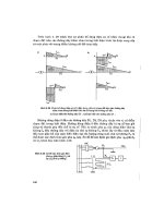
FIGURE 7.26 Cross-section of multi-bored plate.
By the principle of superimposition of effects, the stress conditions generated
by external pressure, internal pressure and axial preload can be considered sepa-
rately.
The holes are assumed to be of the through type and have a diameter which is
constant, with the geometry of the valve section unchanged in any plane perpen-
dicular to the valve body axis. Without axial stress, the calculation approach brings
up the problem of an elastic body in a plane stress condition. Consequently, the
problem consists of establishing the stress condition due to external and internal
pressure in a plate geometrically schematized in Fig. 7.26.
The plate has three axes of symmetry, 60
Њ apart, which correspond to the di-
ameters through the hole centers. In this structure, the greatest stresses are on the
inner edges of the holes, particularly on the points lying on the axes connecting
two adjacent holes and on the axes of symmetry. The most interesting points (Fig.
7.26) are used to compare different calculations.
The stress condition of this elastic body could be determined through an exact
procedure, i.e., analytically, by solving the elastic problem, or through approximate
procedures using:
•
Existing formulas for comparable geometrical bodies
•
The finite element method
25,26
•
Strain gages on the piece boundary
•
Photoelastic models
7.32 CHAPTER SEVEN
Solving a plane problem using the elasticity theory,
27
means finding the Airy func-
tion.
The stress function is complex due to the presence of several boundaries inside
the plate and consequently the resolution of the equation system defining the elastic
problem will also be very troublesome. An analytic solution of a similar case has
been found by Kraus.
28
Evaluation of the stress distribution on the valve body can also be made using
equations for thick-walled cylinders under external and internal pressure.
28
In the
case of cylinders with a central hole, the formulæ are to establish the stress distri-
bution in any point of the radial thickness. More complex are the equations for
cylinders having eccentric holes,
28
giving circumferential stress in any point of the
external and internal boundary. A further evaluation of circumferential stress can
be made, (only for the points in Fig. 7.26) by utilizing existing studies on stress
concentration factors in plates, whose notches are represented by holes.
29
In this
case, the plate is assumed to be compressed uniformly, as in a solid cylinder, with
the pressure acting on the outside. Variations in the circumferential and radial
stresses on the required points referring to the center of the valve body being
known, the circumferential stresses, resulting from the presence of the holes, can
be determined. Furthermore, holes of different diameters require further simplifying
assumptions.
Strain Gage Method. A model of the plate was equipped with strain gages on
external and internal surfaces to measure the trend of the circumferential stresses
on the boundaries, with pressure acting inside and outside.
24
The model was bigger
than the valve, to allow positioning of the strain gages on the internal surface and
because of seal problems in the passage area of the connecting wires to the strain
gages. The test pressure value was kept under 30 MPa (4350 psi). To minimize
effects of systematic and accidental errors of the measuring instruments, the value
of the microstrains undergoing measurement was increased, by adopting a light
alloy model instead of steel, having a normal modulus of elasticity E
ϭ 72500
MPa (10,512,500 psi) (about 1/3 that of the steel used for the valve). To eliminate
uncertainties as to the elastic properties of this material, some specimens were taken
from the piece the model was made from, to obtain the Young’s modulus and
Poisson’s ratio for converting the microstrains into stresses.
FEM Application. The calculations were made with pressure acting separately
on the external and internal peripheries. It was assumed, according to the symmetry
of the system, that there was no rotation in the nodes determining the diameters of
the half-plate, and that displacement would occur only in the direction parallel to
the circumference. The procedure used for calculation involved finite elements with
triangular elements having three nodal points, with the general element having 6
degrees of freedom and a linear shape function,
24
whose trend of stresses is shown
in the graphs in Fig. 7.27 in relation to pressure.
The trend of circumferential stress with pressure acting on the outside is similar
on hole edges. In fact, its lowest values comply with those predicted in points A2.1,
A3.1, A2.2 and A3.2. The lowest value (
c
/p
e
ϭϪ2.9) is assumed to be at point
VERY HIGH PRESSURE COMPRESSORS 7.33
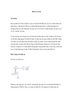
FIGURE 7.27 Circumferential and radial stresses on
plate edge and symmetry axes.
A.3.2, i.e., the internal boundary point of the hole having the smallest diameter
and also related to the straight line joining the centers of two adjacent holes. The
highest value (
c
/p
e
ϭϪ1.9) is at point A4.2, i.e., at the smallest hole, toward the
plate center and along a symmetry axis. Furthermore, with internal pressure, the
curves of circumferential stresses on the inner edge of the holes show a similar
trend, the highest value being point A3.2. The trend of circumferential and radial
stresses is alike (Fig. 7.27), both in the case of external pressure and that of pressure
in the holes.
The sum of circumferential or radial stresses in the case of external pressure
and unit internal pressure is constant and equal to
Ϫ1, i.e.
(
/p ϩ
/p ) ϭϪ1
ce ci
The foregoing can be proved analytically for thick cylinders with centered or ec-
centric holes, as formulæ exist for stresses along the thickness and at the boundary
respectively. In any case, if unit pressure exists inside and outside a cylinder, the
stress condition is the same at any point of the thickness and the hoop and radial
stresses are:
/p ϭ
/p ϭϪ1
cr
This is the result of two different loading conditions, with external and internal
pressure; the above equation can thus be obtained by the superimposition effect.
These statements apply to any type of stress (hoop, radial or direct, according to
the reference axes) involving multiconnected domains, regardless of boundary
7.34 CHAPTER SEVEN
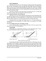
FIGURE 7.28 Comparison of theoretical and experi-
mental results on multi-bored plate.
shape, provided the internal pressure is considered on all internal profiles at the
same time.
Comparison of Results. In a polar-type representation (Fig. 7.28), the values are
compared with different methods. The stresses due to internal pressure are brack-
eted.
24
The trends of the curves determined according to the finite element method
and the experimental measurements are similar, and the stress values are very near.
The experimentally determined values, except for the central zone of the small
hole, are slightly higher than those calculated with the finite elements. At the area
of greatest concentration (points A3.1 and A3.2), the results practically coincide.
The use of conventional equations led to results sufficiently in accordance with
one another and generally lower than those obtained through the finite element
method. This occurs especially at the point of greatest concentration when the thick
cylinder formulæ are used. At the same points, according to the theory of notches,
the results practically coincide with those obtained through the finite element
method and experimental measurements.
Knowledge of the effective stress condition, proper choice of materials and ob-
taining a high degree of finite elements in the zones of greatest stress concentration
makes it possible to arrive at the actual safety coefficient and thus ensure reliability
against fatigue failure.
VERY HIGH PRESSURE COMPRESSORS 7.35
7.3 PACKING AND CYLINDER CONSTRUCTION
7.3.1 Technical Solution for Cylinder Components
Two solutions have been used for this special pressure vessel:
•
A hard metal liner (sintered tungsten carbide with 9 percent cobalt binder),
shrink-fit into a steel cylinder, on which a piston equipped with special piston
rings (Fig. 7.16) was sliding
•
A packing arrangement cup housing the seal rings, with a hard metal plunger
(Fig. 7.8)
Although the first solution was providing fairly good results, it was more affected
by plant conditions, low polymers and catalyst carrier as the lubrication was ob-
tained by injecting oil into the gas suction stream. The packed plunger solution is
less influenced by such factors, considering that the lubricant is injected directly
onto the sealing elements through holes and grooves on the packing cups.
The technological development of sintering WC (11 to 13 percent Co) plungers
of large size in one piece, the lower quantity of oil consumed, the excellent per-
formance, and other process considerations
21
led to preferring packed plungers over
liners on the compressors manufactured in the last 25 years.
The selection of materials for components under pressure is very important.
Mechanical properties must always be carefully analyzed and, when extreme
fatigue conditions exist, aircraft-quality electroslag or vacuum arc remelted steels
should be utilized. To obtain adequate fatigue strength of pressure components, it
is necessary to use autofrettage when operating pressures are very high.
Sealing surfaces between cylinder components play an important role in achiev-
ing good cylinder performance. These are normally flat annular surfaces lapped to
a finish of 0.2 microns CLA* and pressed together by tie rods so that their resulting
load provides sufficient contact pressure to achieve seal. Since little can be done
to modify the actions the cups are subjected to during operation, care should be
taken to prevent the consequences of accidental surface defects by performing local
precompression treatments, such as cold rolling, shot peening, ionitriding etc.
Special attention is required for the surface finishing of elements in direct contact
with the fluid subjected to pulsating pressure. In order to eliminate superficial faults
as much as possible, which could cause fatigue failure, very high grade finishes
are required. Tungsten carbide plungers and liners have surfaces with 0.05 microns
CLA; with the additional advantage of reducing to a minimum the coefficient of
friction between the moving parts. It is difficult to obtain these low roughness
values on the gas passages in the cylinder heads and on the surfaces of steel
cylinders in general, without the use of special machinery.
*CLA ϭ Center Line Average.
7.36 CHAPTER SEVEN
With a surface finish of 0.8 microns (32 microin.), fatigue life is reduced by
15% as compared to that of a finish of 0.025 microns (1 microin.) It is not necessary
to obtain perfectly smooth surfaces, as it has been proved that finishes of 0.1
microns (4 microin.) have no greater fatigue resistance than surfaces with roughness
of 0.025 microns (1 microin.).
7.3.2 Sliding Seals Between Piston and Cylinder at Very High
Pressures
The contact between the sliding parts for adequate sealing is severe for packing
and particularly for piston rings. Under normal pressure, as the relative movement
is parallel and does not allow perfect lubrication, only a transient condition of film
lubrication and dry friction exists. Oil particles, between the contact points, prevent
galling, but to keep the friction coefficient within allowable limits, and to avoid
excessive heat generation, a correct selection of materials (chemical and physical
properties) is necessary. Experience has shown that the most suitable materials for
sealing elements are bronzes, having good wear resistance and mechanical prop-
erties.
Cast iron and bronze or various combinations of these metals were used in the
past for piston rings. Special bronzes are still utilized for packing sealing elements,
although plastic elements can be used up to 250 MPa (36250 psi) when the process
requires low heat generation to avoid decomposition in the cylinder. Relating to
the plunger material, in the past, nitrided steels were used for plungers in ammonia
compressors up to 100 Mpa (14500 psi). Usually, today piston rods are made of
steel coated with tungsten carbide (11 to 13% Co) up to pressure of 60 MPa (8700
psi).
In polyethylene plants, with more severe pressure conditions and more precari-
ous lubrication by white oils, liners or plungers are made of tungsten carbide with
cobalt bonding. When the cobalt content is increased, the hardness decreases, but
the toughness increases, and this quality is more important for plungers than for
liners. Today, the steel plunger coated with tungsten carbide can be used up to 140
MPa (20300 psi), usually on the first stage of secondary compressors.
The sliding surface of plungers and liners should be machined to the maximum
degree of finish obtainable in order to reduce the friction coefficient to a minimum.
Values of 0.025 to 0.05 microns (1 to 2 microin.) CLA of roughness are normally
achieved. In case of WC coated plungers, the surface roughness is 0.1 microns
CLA (4 microin.). The surfaces of sealing elements do not require the same high
quality, since they are softer and on the plunger they are polished during operation,
but still need lapped mating surfaces and more accurate geometry to prevent leaks
and failures.
The life of the sealing elements is influenced by other factors. The stroke and
revolutions per minute (RPM) determining the average piston speed influence the
life, since heat generation increases with speed. The RPM are limited by compres-
sor size and arrangement, dynamic loads on the foundation, operation of the cyl-
inder valves, and pressure pulsation in the gas pipes.
VERY HIGH PRESSURE COMPRESSORS 7.37
The stroke is selected to have a mean piston speed between 2.7 and 3.3 m/s
(530 to 650 ft/min). A long stroke is generally desirable since this exposes a longer
part of the plunger out of the packing, for more effective cooling. The life of sealing
elements is influenced by the system supplying the oil to the cylinder, the amount
and quality of oil, the shape of sealing elements, and the linearity of plunger
movement. A continuous film of oil must be applied to the sliding surfaces. The
type of oil is selected mainly for process reasons (i.e., the need to keep the product
pure), and also its lubricating properties. It is current practice to use white oil.
The shape of the sealing elements used is similar to those used in conventional
machines.
The piston rings solution, with lubricating oil entrained by the gas, needs only
few rings for efficient sealing, but also to enable the one most distant from the gas-
oil mixture to be lubricated. Each combined piston ring is made of two rings in
the same groove, with a further ring mounted beneath. The ring gaps are positioned
out of alignment to give a complete seal effect. On the top of the rings there is a
bronze insert, improving the anti-friction properties and the running-in.
A packing arrangement is usually composed of 5 elements, for pressures up to
350 MPa (50750 psi). In the past, solutions with 3 to 8 sealing elements were also
applied. The ring nearest the pressure is a breaker ring of special shape, suitable
for damping the high pressure fluctuations but not designed to provide effective
seal, as this function is performed by the following ring couples, whose life is
consequently increased.
The amount of oil applied must be controlled accurately, since trouble can arise
from either excessive or insufficient lubrication. If excessive oil is injected and the
seal rings are providing perfect seal, the oil pressure can rise to a value above that
of normal conditions and the contact pressure between rings and plunger could
cause seizure. Of great importance is the linearity of the piston movement, since
it ensures that the sealing elements will not be subjected to irregular operating
conditions and thus forced to assume an incorrect position in their housing, with
consequent overstressing and reduction in life.
It is necessary to keep the temperature low by cooling the plunger with oil
around it, outside of the main packing. This is important mainly to reduce the risk
of thermal cracks on the plunger surface.
7.3.3 Autofrettage of Various Cylinder Components
General Aspects. The use of autofrettage, applied to tubular and vessel-reactors,
has been extended to pumps
18
and to machines operating particularly in tubular-
reactor plants, as it is effective where the probability of fatigue failure is high. This
technique allows components to be built using materials with lower mechanical
properties.
Autofrettage is performed on cylinder heads with combined axial valves, when
high pressures are involved, as gas pulsations are still present and fatigue must
always be taken into consideration. Cylinder chambers and packing cups are ex-
cluded, as they can reach adequate prestress levels through shrink-fitting. Packing
7.38 CHAPTER SEVEN
FIGURE 7.29 Surface seal
with conical seat.
cups with axial holes and oil distribution cups require additional prestress only
inside the lube oil hole. The distribution cup has no shrinkage, and generally has
curved holes normally obtained through a special procedure, such as electro dis-
charge machining (EDM). In this case, a proper polishing procedure should be
applied to fully remove the surface modified by local defects.
Autofrettage of injection quills and check valves operating on ethylene second-
ary compressor second stages is also common practice when pressures are very
high. Cylinder heads with radial valves are shrink-fit and are autofrettaged only
when differential pressure between suction and discharge is very high. Autofrettage
pressure is determined by operating conditions, geometry, presence of prestresses
(due to shrink-fitting), and properties of the material. Autofrettage pressures for
hypercompressor cylinder parts range between 500 MPa and 1300 MPa (72500 to
188500 psi).
30
Autofrettage of axial holes is performed after shrink-fitting of the
cup on the finished piece, only upon completion of machining before final lapping
of the mating surfaces. In this case, autofrettage pressure has been applied up to
1100 to 1300 Mpa (160000 to 188500 psi).
Test Rigs and Seals Arrangement. Few types of seals withstand very high pres-
sure applications, due to the fact that the geometries of the cylinder components
to be autofrettaged are often complex. On polyethylene compressor cylinder parts,
seals are restricted to conical seating surfaces, metal gaskets, plastic O-rings and
special arrangements:
30
•
The cone solution (Fig. 7.29), typical of high pressure tubing, has been applied
up to 1300 MPa (188500 psi).
•
Annealed copper gaskets are used up to 1300 MPa (188500 psi) (Fig. 7.30).
•
Viton O-rings are employed for small-diameter seats, tapered (Fig. 7.31) or flat
(Fig. 7.32), protected against extrusion by the metallic contact between the parts.
VERY HIGH PRESSURE COMPRESSORS 7.39
FIGURE 7.30 Metal seal.
FIGURE 7.31 Plastic O-ring
with conical seat.
Positive results were obtained on diameters up to 76 mm. (3 in.) and up to 900
MPa (130500 psi) for the latter solution.
•
Self-sealing arrangements (Fig. 7.33) are used for wider diameters, in order to
follow the bore, subject to considerable strain under high pressures.
These seals are made as follows:
•
A seamless plastic O-ring with hardness between 75 to 90 Shore A, with good
surface finish
•
Hard plastic (a polyamide resin) and geometrically precise shoulder rings. Di-
mensions have to be carefully checked, as plastics are subject to alteration with
the passage of time.
•
Bronze antiextrusion rings with a 45Њ angle
•
Bronze rings to preload the seal assembly and to guide the inner core of the
device
In autofrettage of radial valve cylinder heads, similar seals are used and internal
mandrels are applied to reduce fluid volume. Axial valve cylinder heads are auto-
frettaged (Fig. 7.34) with special seals (Fig. 7.33) to achieve seal on the large inner
diameter which can be accomplished by providing a smooth surface finish and
7.40 CHAPTER SEVEN
FIGURE 7.32 Plastic O-ring
with flat seat.
FIGURE 7.33 Special seal with O-ring.
using great care in assembling the rig to avoid local damage in the seal zone. An
internal bar reduces fluid volume. The seals are preloaded, the assembly is balanced
and no additional support is required for the inner core. Lateral (suction and dis-
charge) holes are plugged by flanges using combined metallic and O-Ring seals
(Fig. 7.32). Autofrettaged packing cup axial holes (Fig. 7.35) use metal seals (Fig.
7.30). The test rig for the oil distribution cups uses axially-directed seal (Fig. 7.30)
and radial seal (Fig. 7.31). Autofrettage of injection quills utilizes cone seals (Figs.
7.29 and 7.31).
Autofrettage Procedure. In equipments operating at very high hydrostatic pres-
sures, the fluid must be able to transmit pressure without undergoing freezing ef-
fects, related to fluid properties, operating temperatures and tubing size. Pressure
may increase at the pump and, due to solidification problems within the tubing,
may be much lower inside the piece to be autofrettaged.
Brake oils have been used up to 500 MPa (72500 psi) with some drawbacks
(i.e., corrosion on pump seal rings caused poor performance). Prexol 201 over-
comes solidification problems and gives adequate intensifier plunger seal life, up
VERY HIGH PRESSURE COMPRESSORS 7.41
FIGURE 7.34 Apparatus for autofret-
tage of axial valve heads.
FIGURE 7.35 Apparatus for autofrettage of packing
cups.
7.42 CHAPTER SEVEN
to 1300 MPa (188500 psi). As oil properties are altered by use at the highest
pressures, oil should be changed frequently.
The whole autofrettage process is controlled by resistance strain gage-type trans-
ducers to check pressure at pump discharge, close to the piece undergoing auto-
frettage and, if critical conditions exist, at the end of the circuit or at the far side
of the cylinder component.
Strain gages on the outer surface of the piece are used when an autofrettage
procedure must be defined for the first time, or in case of complex shapes, and
may detect internal pressure or deviations in mechanical properties. For safety
reasons, dimensional checks are performed after autofrettage.
The inner diameter of axial valve cylinder heads should be checked, to assess
the amount of metal to be removed, which should be as small as possible in order
to preserve the benefits of prestressing. At plastic strain conditions, duration of
tests appreciably affect the final results. Pressure should rise slowly to allow strain
to take place completely during each loading condition. In short tests, yield point
and ultimate tensile stress are increased while strain decreases. In the case of steel,
a pressure rise of 10 MPa (1450 psi) per second is on the safe side. Generally, the
test requires a pressure rise of 5 minutes minimum. Pressure increase is related to
the volume of the fluid in the whole system and its components (tubing and the
intensifier). The autofrettage pressure is maintained for 15 minutes (5 minimum)
and a slow pressure decrease takes place in about 5 minutes. Slow return to final
conditions eliminates errors in dimensional measurements, allows time to check
the autofrettage effect, and allows the special seals to return to their original po-
sitions in their housings after having undergone severe strain, thus reducing dis-
assembly problems.
Very high pressure systems have potential hazards, although risks are not as
great as when gases are handled, due to the great energy involved (the fluid pos-
sesses compressibility and can be trapped inside the system). If gaskets in the
hydraulic system fail, the jettisoned particles could cause injury to people or dam-
age objects. Fluid leak at high speeds, reduced by the small volumes involved, is
another risk. To prevent air from being trapped in the hydraulic circuit during test
rig assembly, a vent valve is temporarily opened at the highest point of the circuit
and oil is allowed to drip out, prior to tightening. To reduce risks from stored
energy, the volume of the system is reduced: the piping is made as short as possible
and suitable inner cores are used in large components like cylinder heads. The
compact system is positioned in a safe area (bunker with fencing around the equip-
ment to protect the surroundings). Steel shield between assembly and pump and
metal sheets around the pressure tubes are added protection. The operator’s work
station is separate. Before disassembling any part of the test rig, the pressure is
relieved from the circuit.
Some authors,
31,32
advise heat-treating the material at about 250ЊC for an hour
to allow component dimensions (i.e., eliminating flexural stresses without affecting
residual body stresses)
33
and the material elasticity to be restored. (Others recom-
mend higher temperatures.) At the same or higher temperatures, decarburizing
problems might arise on the surfaces. This is not common practice with polyeth-
VERY HIGH PRESSURE COMPRESSORS 7.43
FIGURE 7.36 Packing assembly.
ylene compressors, as components have proven successful field operation. In any
case, this heat treatment cannot be performed when the tempering temperature of
the material is lower than the heat treatment temperature.
Axial valve cylinder heads, requiring accurate inner bore dimensions, must be
machined after autofrettage. Remachining is also performed in the seat area quills
(oil distribution cup side) and thus the modified prestress level area is quite limited.
Appropriate allowances must be considered, and material removal must take into
account the reduction in the prestress level.
It is generally advisable to perform autofrettage on finished parts. The combi-
nation of autofrettage and shrink-fitting, especially when high ultimate tensile
strength materials are used, is complex. Autofrettage before shrink-fitting is nor-
mally carried out on radial valve cylinder heads, allowing use of lower autofrettage
pressure, with advantages. Lube oil holes of packing cups are autofrettaged at a
pressure of 1100 MPa (159500 psi). Autofrettage contributes to increasing the
availability of secondary ethylene compressors which operate in plants with tubular
reactors or in general when pressures exceed 200 MPa (29400 psi).
7.3.4 Typical Behaviour of Packings
Packings today consist typically of one (or two) split breaker rings and five radial
tangential sealing rings (Fig. 7.36). The rings are made of special bronze alloys,
usually with high lead content, uniformly distributed, so as to guarantee sufficient
strength, low friction coefficient and high thermal conductivity, for a rapid dissi-
7.44 CHAPTER SEVEN
pation of the friction heat through the packing cups. The hardness of the rings
varies from 55 to 80 Brinell (measured with a 10 mm. ball and 500 kg. load).
The plunger on which the sealing elements slide is made of solid tungsten car-
bide, with surface finish of 0.05 microns [2 microin.] CLA. The synthetic lube oil
of the cylinders has lower lubricating properties than oils used for normal services,
since for ethylene polymerization, pollution of the final product must be reduced
to a minimum.
Packing performance is greatly influenced by the above parameters and by the
efficiency of the breaker rings, whose action is very important, as can be seen by
analysing the operating conditions of a packing. The pressure inside the cylinder
can be considered as consisting of a constant portion (suction pressure) and a
fluctuating portion (the difference between discharge and suction). The static pres-
sure distribution tends to overload the last ring (frame side), which has to handle
almost the whole load.
23
This is similar to packings, operating at constant pressure,
for example on ammonia synthesis compressors. The variable pressure increases
due to polytropic compression, and then decreases due to the expansion of the gas
remaining in the clearance volume, and assumes constant values during discharge
and suction effect.
Breaker rings oppose a rapid pressure increase in the cylinder, limiting gas leak-
age and reducing the propagation of the pressure wave towards the seal rings. Their
most important function, however, is to delay the ‘‘backflow’’ from the packing
rings towards the cylinder chamber, when the plunger begins its back stroke. If
this action is inadequate, the pressure upstream of the first sealing element will
suddenly drop to the suction value, due to the steep slope of the expansion curve.
The resultant of the forces acting on the first sealing ring is suddenly inverted,
causing rapid expansion of gas under the radial and especially under the tangential
ring, which exerts a stronger sealing action, with the following problems:
•
Breakage of the dowel pin between radial and tangential ring
•
Breakage of the lips of the tangential cut rings
•
Damage to the garter springs of the sealing element
When, after a certain period of operation, the first sealing pair no longer per-
forms its function, the problems occur in the second pair and the process of pro-
gressive damage continues through the various rings of the packing. To analyze
the operating conditions, behaviour and performance of packings, measurements
were taken at the lube oil injection quills and in the compression chamber (Fig.
7.37) of a first and second stage cylinder on a compressor having a capacity of
53,000 kg/hr (1945 lb/min), operating in a plant with a vessel reactor. Packings
had a three piece pressure breaker ring, with small circumferential clearance and
five grooves of radial tangential seals (with axial clearance of about 0.15 mm. [.006
in.]). The distribution of the pressures along the packing in relation to the crank
angle (Fig. 7.37) and during the suction and discharge strokes (Fig. 7.38) is quite
similar on first and second stage.
23
In general, the first three sealing elements are affected by the pressure fluctuation
of the cylinder, while the last two are subjected to an almost steady pressure (Fig.
VERY HIGH PRESSURE COMPRESSORS 7.45
FIGURE 7.37 Operating pressures on a 1st and on
a 2nd stage cylinder.
FIGURE 7.38 Pressure distribution
on the 2nd stage packing during dis-
charge and suction stroke.
7.46 CHAPTER SEVEN
FIGURE 7.39 Wear distribution on 1st and 2nd
stage packings.
7.38). The pressure variation occurring at the first sealing pair is propagated to the
following elements in the proportion of 70% on the second pair, 30% on the third
and a negligible amount on the two final sealing elements. The steady pressure, at
the external oil injection quill, does not significantly change and therefore about
60% should be supported by the last sealing pair, in the hypothesis of labyrinth
behaviour.
34
Pressure pulsations, upstream of the suction valve and downstream of
the delivery valve, may have an influence on the cycle pressures in the cylinder
(Fig. 7.37). The pressure breaker rings behaviour appears good since the delaying
action is evident during the compression period and a considerable sealing effect
is evidenced in both stages during compression and expansion. The breaker ring,
in fact, withstands about 80% of the pressure fluctuation, (100 MPa [14500 psi] in
the second and 70 MPa (10150 psi) in the first stage). The efficiency is higher in
the first stage, due to the greater variability of the specific volume of the gas (5%
in the second and 16% in the first stage). This may be partly explained by the
difference between the polytropic coefficient in first and second stage. It should be
recalled that when the physical conditions of a gas are close to those of a liquid,
the task of the breaker ring is more difficult and its effect is lower.
The fluctuating part of the pressure affects the first three seal rings, with the
second and third withstanding a differential pressure of 50% and 30% as compared
to the first sealing couple (Figs. 7.37 and 7.38). The steady part of the pressure is
mainly supported by the last two sealing elements.
Some packings were dismantled and analyzed after 10,000 to 20,000 hours of
operation. The wear of each radial and tangential element was compared (Fig. 7.39)
VERY HIGH PRESSURE COMPRESSORS 7.47
and there was a similar wear pattern curve for radial and tangential rings. For first
or second stage, the trend for higher wear is on the first and last elements. The
wear rate is higher in tangential rings as compared with radial ones. On first stage,
the first pair did not wear completely, as the dowel broke, due to ‘‘backflow’’ and
then the pressure loaded the second pair, causing accentuated wear. Wear on the
tangential ring higher than the amount allowed by the butt gap is frequently ob-
served due to non-uniform wear on the rings, resulting from the high pressures and
forces acting on them. On the second stage, the ‘‘backflow’’ caused breakage of
the springs (of the coil type) of the first pair and later breakage of the dowel pin
of the second pairs. The work of withstanding the variable pressure was then carried
out by the third sealing element.
The maximum wear on the frame side elements of both stages is due to the
constant pressure to which they are subjected, considering that lubricating condi-
tions are not optimal. Wear on the radial ring of the last pair of the first stage
packing is an exception, encountered in other compressors, which can be explained
as follows: The radial rings, subject to steady pressure, tend to remain in their
position without effecting an appreciable sealing action towards the plunger, but
simply creating a barrier to the pressure at the cuts of the tangential rings. In the
zone subject to variable pressure, the first radial rings are forced to exert a sealing
action on the gas that tends to re-enter the cylinder during the suction phase. The
sealing effect is not complete, since the radial cuts allow the gas passage.
A general wear pattern can be derived connected with the pressure distribution
along the packing (Fig. 7.39). The steady portion of the pressure causes a type of
wear with maximum values reached on the frame side sealing ring. The fluctuating
portion of the pressure causes wear with an opposite trend, with the highest values
on the first sealing pair. The resultant wear will be a curve with its maximum
values at the extremities of the packing. Generally, the theoretical maximum value
is either towards the first ring (pressure side) or towards the last (frame side)
depending on the predominance of the fluctuating or the steady portion. The prac-
tical wear pattern is different as the ‘‘backflow’’ can make some sealing elements
inefficient. The performance of the sealing elements is strongly influenced by op-
erating conditions, lubrication and alignment. The normal plunger runout is within
0.075 mm. (.003 in.), as easily measurable by proximity probes, with alarm 0.15
mm. (.006 in.) and trip 0.2 mm (.008 in.). Long life of packing rings has been
reported up to 65,000 operating hours, with 180 MPa (26100 psi) final pressure.
7.4 BIBLIOGRAPHY
1. Crossland, B., K. E. Bett, and Sir Hugh Ford: Review of Some of the Major Engineering
Developments in the High-Pressure Proc. Polyethyene Process, 1933–1983, Institute of
Mechanical Engineering, 1986, Vol 200, Ne A4.
2. Andrenelli, A., ‘‘Reciprocating Compressors for Polyethylene Production at Pressures
Higher Than 3000 Atmospheres,’’ Quaderni Pignone 13.
7.48 CHAPTER SEVEN
3. Traversari, A., M. Ceccherini, and A. Del Puglia, Advanced Elastic Analysis of Com-
pressor Cylinders for H.P. Low Density Polyethylene Production, ASME Joint Confer-
ence of the PVP, Materials, Solar and Nuclear Engineering Division, Denver, Colorado,
June 21–21, 1981, Session 0A–6.
4. Traversari, A., and F. Bernardini, ‘‘Aspects of Research on Secondary Compressors for
Low Density Polyethylene Plants,’’ Quaderni Pignone 25, June 1978, pp. 123–124.
5. Vinciguerra, C., U.S. Patent 3, 581.583 to Nuovo Pignone S.p.A., January 15, 1969.
6. Andrenelli, A., ‘‘Special Features in Reciprocating Compressors for Polyethylene Pro-
duction,’’ Proceedings of the Industrial Reciprocating and Rotary Compressors: Design
and Operational Problems, Institution of Mechanical Engineers, Vol. 184, Part 3R, Oc-
tober 13–16, 1970, pp. 106–113.
7. Traversari, A., P. Beni P., Approaches to Design of a Safe Secondary Compressor for
High Pressure Polyethylene Plants, High Pressure Symposium: Safety in High Pressure
Polyethylene Plants, Tulsa, Oklahoma, March 12–13, 1974.
8. Giacomelli, E., and M. Agostini, Safety, Operation and Maintenance of LDPE Secondary
Compressors, ASME PUP Division Conference, New Orleans, Louisiana, 1994.
9. Manning, W. R. D., ‘‘Ultra-high-pressure Vessel Design, Pt. 1,’’ Chem. Proc. Eng.,
March, 1967.
10. Morrison, J. L. M., B. Crossland, and J. S. C. Parry, ‘‘Fatigue Strength of Cylinders
with Cross Bores,’’ J. Mech. Eng. Sci. 1959 1 (N. 3).
11. Parry, J. S. C., ‘‘Fatigue of Thick Cylinders: Further Practical Information,’’ Proc. Inst.
Mech. Engrs 1965–66 180 (Pt. 1), 387.
12. Chaaban, A., K. Leung, and D. J. Burns, ‘‘Residual Stress in Autofrettaged Thick-Walled
High Pressure Vessels,’’ PVP, Vol. 110, 1986, pp. 56–60.
13. Kendall, D. P., ‘‘The Influence of the Bauschinger Effect on Re-Yielding of Autofret-
taged Thick-Walled Cylinders,’’ ASME Special Publication, P. V. P. , Vol. 125, July, 1987,
pp. 17–21.
14. Yang, S., E. Badr, J. R. Sorem, Jr., and S. M. Tipton, ‘‘Advantages of Sequential Cross
Bore Autofrettage of Triplex Pump Fluid End Cross Bores,’’ P. V. P. , Vol. 263, High
Pressure—Codes, Analysis and Applications, ASME, 1993.
15. Manning, W. R. D., Design of Cylinders by Autofrettage, Engineering (April 28, May 5
and May 19, 1950).
16. Chaaban, A., and N. Barake´, ‘‘Elasto-Plastic Analysis of High Pressure Vessels with
Radial Cross Bores,’’ P. V. P. , Vol. 263, High Pressure—Codes, Analysis and Applica-
tions—ASME, 1993.
17. Chaaban, A., ‘‘Static and Fatigue Design of High Pressure Vessels with Blind-Ends and
Cross Bores,’’ Ph. D. Dissertation, University of Waterloo, 1985.
18. Chaaban, A., and D. J. Burns, ‘‘Design of High Pressure Vessels with Radial Cross
Bores,’’ Physical 139, 140B, pp. 766–772, North-Holland, 1986.
19. Rees, D. W. A., ‘‘The Fatigue Life of Thick-Walled Autofrettaged Cylinders with Closed
Ends,’’ Fatigue Fract. Eng. Mater. Struct., Vol. 14, pp. 51–68, 1991.
20. Rees, D. W. A., ‘‘Autofrettage Theory and Fatigue Life of Open-Ended Cylinders,’’
Journal of Strain Analysis, Vol. 25, pp. 109–121, 1990.
21. Parry, J. S. C., ‘‘Fatigue of Thick Cylinders: Further Practical Information,’’ Proc. Inst.
Mech. Eng., 1965–66, 180 (Part I).
VERY HIGH PRESSURE COMPRESSORS 7.49
22. Kendall, D. P., and E. H. Perez., ‘‘Comparison of Stress Intensity Factor Solutions for
Thick-Walled Pressure Vessels,’’ P. V. P. —Vol. 263, High Pressure—Codes, Analysis and
Applications, ASME, 1993.
23. Traversari, A., and E. Giacomelli, ‘‘Some Investigation on the Behaviour of High Pres-
sure Packing Used in Secondary Compressors for Low Density Polyethylene Produc-
tion,’’ Proceedings of the 2nd Int. Conf. on H.P. Engineering, University of Sussex,
Brighton, England, July 8–10, 1975, pp. 57–58.
24. Giacomelli, E., ‘‘Finite Element Method on Polyethylene Compressor Valves Design,’’
Quaderni Pignone 26, January 1979, pp. 19–25.
25. Zienkiewicz, O. C., ‘‘Axi-Symmetric Stress Analysis,’’ The Finite Element Method in
Engineering Science, (London, Eng.: McGraw Hill, 1971), pp. 73–89.
26. Tottenham H., and C. Brebbia, Finite Element Techniques in Structural Mechanics
(Southampton, Eng.: Millbrook).
27. Muschelisvili, Some Basic Problems of the Mathematical Theory of Elasticity, Moscow,
1949.
28. Kraus, H., ‘‘Pressure Stresses in Multibore Bodies,’’ Int. J. Mech. Sci. (Pergamon Press
Ltd., 1962), Vol. 4, pp. 187–194.
29. Peterson, R. E., Stress Concentration Design Factors (New York, N.Y.: John Wiley and
Sons, 1974).
30. Giacomelli E., P. Pinzauti, and S. Corsi, Autofrettage of Hypercompressor Components
up to 1.3 GPa: Some Practical Aspects, ASME PUP Division Conference, Orlando,
Florida, 1982.
31. Vetter, C., and H. Fritsch, ‘‘Zur Berechnung und Gestaltung von Bauteilen mit Bean-
spruchung durch schwellende Innendruck,’’ Chemie Ingr. Tech., 1958, 40 (n. 24).
32. Morrison, J. L. M., B. Crossland, and J. S. C. Parry, ‘‘Strength of Thick Cylinders
Subjected to Repeated Internal Pressure,’’ Proc. Inst. Mech. Eng., 1960, 174 (no. 2).
33. Giacomelli, E., and P. F. Napolitani, ‘‘Ricerca Sperimentale sul Comportamento degli
Accoppiamenti Forzati Albero-mozzo,’’ Thesis, Dept. Mech. Eng., University of Pisa,
Italy, 1969.
34. Cosimi, L., ‘‘Il Compressore a Pistone a Secco con Tenuta a Labirinti,’’ Il calore, 1961—
N. 3.
35. Faupel, J. H., and F. E. Fisher, Engineering Design, (New York, N.Y., Chichester, Bris-
bane, Toronto: John Wiley and Sons, 1981).
36. Whiteley, K. S., Ullmann’s Encyclopedia of Industrial Chemistry, Vol. A21, Section
1.5.1, Polyofins, 1992.
8.1
CHAPTER 8
CNG COMPRESSORS
Mark Epp
Jenmar Concepts
8.1 INTRODUCTION
The introduction of natural gas as a fuel for automotive and mass transportation
has provided an entirely new application for the compressor. The problems of
energy supply shortages, poor air quality and high energy costs have contributed
to the importance of natural gas as an alternative to crude oil based fuels.
Natural gas is a mixture of gases in which the primary constituent is methane,
typically at 85.0 to 95.0 mole percent.
As a transportation fuel, stored natural gas must be compressed for an increase
in energy density. The compressor is used to boost the pressure of natural gas and
is the primary equipment of the compressed natural gas (CNG) refueling station.
8.2 CNG COMPRESSOR DESIGN
The compressor type used is the multi-stage reciprocating piston compressor. Com-
pressor size commonly ranges from 25 to 250 brake horsepower (BHP). The design
of the CNG compressor resembles the high pressure air compressor but with some
important differences.
8.2.1 Suction And Discharge Pressures
Discharge pressures of 3600 to 5000 psig preclude the use of the multi-stage re-
ciprocating piston compressor. Suction pressures are site specific and dependent on
the operating pressures of the local gas utility distribution pipeline. Suction pres-
sures can range from inches water column to 1000 psig. Most often pressure reg-
ulation and metering is supplied by the gas utility providing stable suction pressures
to the compressor. To minimize energy consumption, CNG compressor manufac-
8.2 CHAPTER EIGHT
FIGURE 8.1 Compressed natural gas refueling station (courtesy of IMW Altas
Inc.).
turers configure compressors specific to the application and suction gas pressure
available (refer to Fig. 8.2).
The total pressure ratio from suction pressure to discharge pressure determines
the number of compressor stages used. For the same pressure ratio, a natural gas
compressor will generate lower discharge temperatures than an air compressor. This
is due to the lower specific heat ratio property (k
ϭ C
p
/C
v
) of natural gas relative
to air. For this reason, natural gas compressors of similar technology can operate
at higher pressure ratios than air compressors. The gas discharge temperature of a
compressor stage is one of the limiting factors determining maximum stage pressure
ratio. The maximum discharge temperatures allowable are a function of the ac-
ceptable operating temperatures of the sealing materials used, including piston
rings, rod rings, o-rings and gaskets. Avoiding high discharge temperatures also
decreases compression horsepower. To maintain satisfactory discharge temperatures
a suitable number of compression stages must be selected. Table 8.1 provides a
guide to the number of compressor stages required for a given suction pressure.
There is some overlap of suction pressure ranges. Some compressors, such as those
with oil lubricated and cast iron piston rings can operate at higher pressure ratios
than compressors using nonlubricated and special material piston rings such as the
filled Teflons
TM
.
CNG COMPRESSORS 8.3
FIGURE 8.2 Compressor brake horsepower vs suction pressure.
TABLE 8.1
Compressor Stages vs Suction Pressure
Suction pressure (psig) No. of stages Discharge pressure (psig)
6؆ H
2
O-10 5 3600–5000
6
؆ H
2
O-100 4 3600–5000
80–350 3 3600–5000
250–1200 2 3600–5000
1000
ϩ 1 3600–5000
8.2.2 Compressor Sealing
Natural gas is a flammable gas. It has also been identified as an atmospheric green-
house gas. CNG compressors are designed to eliminate or severely restrict gas
leakage emissions. Uncontrolled leakage may result from random leaks that occur
in the piping system or compressor caused by static seal failures. Controlled leakage
is expected leakage from compressor rod packings and seals. As industrial emis-
sions standards tighten, consideration must be given to CNG compressor manufac-
turer’s gas leakage rate data.
8.4 CHAPTER EIGHT
FIGURE 8.3 Pressurized crankcase compressor (courtesy of Compair
Reavell Limited).
Pressurized Crankcase. Compressors with pressurized crankcases collect seal
leakage gas in the crankcase and recycle it into the suction pipe. No leakage gas
is lost to the atmosphere. The crankcase is pressurized at suction pressure. Special
rotating shaft seals prevent gas leakage from crankshaft drive end extensions. Most
pressurized crankcases are limited in use to suction pressures below 250 psig,
however compressors with higher seal operating pressures are available.
Pressurized crankcases are most often used on trunk piston type compressors.
Trunk pistons have a linear guide and piston as one integral part. There is no rod
sealing between the piston and linear guide. Without a linear traveling piston rod
and seals (see Atmospheric Crankcase, below), piston ring leakage flows into the
crankcase. To hold leakage gas at suction pressure, the crankcase must be designed
as a pressure vessel with heavy rounded walls and internal or external structural
ribs (see Fig. 8.3). Some pressurized crankcase compressors use a cantilevered shaft
to eliminate one shaft seal. Other components including oil lubrication systems,
static seals on inspection plates and cover seals must withstand the elevated pres-
sures.
Atmospheric Crankcase. Compressors with atmospheric crankcases commonly
use double acting cylinders and crossheads. Crossheads allow the use of a piston
rod which moves linearly and compresses both to the head and crank end (see Fig.
8.4). The piston rod is readily sealed using a series of rod packings. Rod packings
are assembled in a packing case with gas leakage vented and piped for discharge
CNG COMPRESSORS 8.5
FIGURE 8.4 Atmospheric crankcase compressor (courtesy of Gemini Engine Company).
to atmosphere. New rod seal leakage can be very low and commonly less than
0.1% of total cylinder mass flow rates. Most compressors of this type vent the gas
at source rather than allowing the gas to leak into the crankcase. The crankcase
operates at atmospheric pressure, eliminating the need for special shaft seals, gas-
kets, and elevated pressure lubrication systems.
The atmospheric crankcase is most suitable for large compressors where design
for pressure containment is difficult. Atmospheric crankcase type compressors us-
ing rod sealing also allow compressors to be designed for high gas suction pressures
beyond what is practical for pressurized crankcase type compressors. In addition,
maintenance procedures are less onerous, allowing crankcase inspections without
depressurization.
Blow Down Gas Recovery. Similar to air compressors, the natural gas compressor
must be depressurized for start up. This necessitates that on shutdown, gas en-
trapped in the compressor and piping system must be vented. Unlike an air com-
pressor which can be vented to atmosphere, the natural gas compressor must be
provided with a blow down gas receiver tank. This tank must be adequately sized
8.6 CHAPTER EIGHT
to allow the compressor to depressurize and reach a pressure equilibrium suffi-
ciently low for compressor start up.
Upon compressor depressurization, valves may operate under sonic or choke
flow conditions during blow down. Sonic gas velocities will quickly erode the seats
and seals of some valves. Sonic flow can be managed by using line orifices, special
valve seat materials, or specially designed valves which protect seats and seals
from direct flow impingement.
8.2.3 Lubrication
Compressor lubrication has become an issue of debate within the CNG industry.
Lubricated compressors require lubrication of piston rings, rod packings and valves.
Nonlubricated or oil free compressors use special materials for these components,
eliminating the need for additional oil injection. Proponents of nonlubricated com-
pressors claim that they achieve the highest discharge gas quality. Proponents of
lubricated compressors maintain that with well engineered lubrication and filtration
systems, similar discharge gas quality is attainable. A lubrication oil carry over
limit maximum of 0.5 lb/mmscf at compressor discharge has become a common
industry standard. This standard can be met using nonlubricated compressors or
lubricated compressors with filtration.
In deciding lubricated versus nonlubricated, other factors to consider are outlined
in Table 8.2.
8.2.4 Piston Ring and Seal Performance
The extreme gas pressures exerted in the final stages of a natural gas compressor
present some unique design problems. Piston ring wear rates increase dramatically
with increasing stage pressures. High pressure differentials across piston rings con-
tribute to ring extrusion between the piston and cylinder clearances. Lowering clear-
ances reduces ring extrusion, but increases the possibility of piston contact with
the cylinder wall as the piston wear bands deteriorate. Extreme pressures also
contribute to high operating PV (the product of surface pressure and velocity)
values of piston rings. The result can be high piston and cylinder wear rates. High
PV also generates high ring surface contact temperatures. These temperatures can
be higher than measured gas discharge temperatures resulting in piston ring material
creep and extrusion. Another less understood factor in piston ring wear is the
apparent loss of oil viscosity at high operating pressures.
High pressure static sealing using compliant and porous o-ring materials can
result in seal failure upon rapid decompression. O-ring materials including Buna-
N and Viton
TM
are porous and allow high pressure natural gas to permeate the
material. If the o-ring is operating at high pressure for some extended time period
and then the compressor shuts down and rapidly decompresses, the gas entrained
in the o-ring will rapidly expand. Failure of the seal is caused by rapid expansion
of entrained gas causing bubbles and lacerations in the o-ring material as the gas