Tunable lasers handbook phần 7 docx
Bạn đang xem bản rút gọn của tài liệu. Xem và tải ngay bản đầy đủ của tài liệu tại đây (1.25 MB, 50 trang )
284
Norman
P.
Barnes
Curved
Reflecting
a\
?
I
Curved
Mirror
output
output
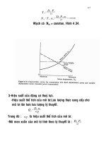
FIGURE
3
3
(b)
Grazing-incidence configuration.
Littrow and Grazing-incidence grating configurations. (a)
Littrow
configuration.
where
N
is the order of the reflection. For gratings used in a laser resonator, the
orders are limited to
1
so
that the losses associated with the higher orders are
avoided. In the following, we assume that the first-order reflection is always uti-
lized. If a grating is used in the Littrow configuration, the incident and reflected
angles are equal.
In
this case, the variation
of
the angle with wavelength is
Using the same expression for the beam divergence, the
bandwidth is
-I
A&
=
(274
"rJ
cos
(8
j)]
.
h
Since
d,
cos(8J can be much larger than
dnldh,
the spectrz
(35)
single-pass spectral
(36)
narrowing achieved
with a &rating can be much larger by employing a grating rather than a prism.
Although greater spectral resolution can be achieved with a grating, the
losses of a grating tend to be higher. Losses are associated with both finite
reflectivity
of
the coating, usually a metal, and less than unity grating efficiency.
Higher losses are particularly pronounced at shorter wavelengths where the
6
Transition Metal Solid-state Lasers
285
reflectivity of the grating is lower since the reflectivity of the metal
is
lower. In
addition, gratings tend to be more damage prone as compared with prisms. Note
that a grating will, in general. polarize a laser. Consequently. the same comments
regarding the losses associated with restricting the laser to operate in a polarized
mode apply. The dispersive characteristics of multiple-prism grating systems are
described in Chapter
2.
Birefringent filters achieve wavelength control by utilizing the variation of the
phase retardation of a wave plate uith wavelength. For normal incidence. the
phase difference
CD
between the ordinaty and extraordinq wave of
ti
nave plate
is
CD
=
274
1ZC,
-11,
)d/h
,
(37)
where tio and
ne
are the ordinary and extraordinary refractive indices. respec-
tively,
d
is the thickness of the wave plate, and
h
is
the aavelength. If a poly
chromatic polarized wave is incident
on
the wave plate. only some of the nave-
lengths will have a phase difference. which is
an
integer multiple of
2x.
These
wavelengths will interfere constructively as they exit from the wave plate and
emerge with the same polarization as the incident polarization. If a polarization
discrimination device is used after the wave plate, only the wabelengths that
have the correct polarization will suffer
no
loss. By using this wavelength vary-
ing loss, a wavelength selective device can be made.
Both birefringent filters and Lyot filters can be made using this principle.
Lyot
filters (681 employ several wave plates
to
achieve better spectral resolution.
Between each wave plate is a polarizer. By using these polarizers, good wave-
length resoliition can be achieved. However, this leads
to
a filter with high trans-
mission losses. High losses are incompatible with efficient lasers.
To obviate
these losses, birefringent filters were created
[69,70].
These devices are nave
plates orientzd at Brewster‘s angle. In this configuration, the Brewster’s angle sur-
faces act as the polarizer, eliminating the polarizer as a loss element. Since the
degree
of
polarization
of
a Brewster’s angle surface is not as high as that
of
a
polarizer, the wavelength resolution is not as high as that of a Lyot filter. Phase
difference between the ordinary and extraordinary waves can be calculated
for
2
wave plate at Brewster’s angle by taking into account the variation of the refrac-
tive index with orientation and the birefringence. Because birefringent filters con-
sist only of wave plates oriented at Brewster’s angle, they can have low loss.
assuming a polarized laser, and can be damage resistant.
Etalons, like birefringent filters. operate on a principle of constructive inter-
ference.
An
etalon consists of two parallel reflective surfaces separated by a
dis-
tance d. Wavelengths that fill the distance betmeen the mirrors with an integer
multiple of half-wavelengths will be resonant: that is. resonance occurs when
286
Norman
P.
Barnes
where
9
is the angle of propagation,
N
is an integer, and
ii
is the refractive index
of the material between the mirrors
[65].
Note that since
n
occurs in these rela-
tions rather than
tio
-
ne,
resonances are much closer together. Because the reso-
nances are closer together and the resolution is related to the wavelength interval
between the resonances. etalons tend to have much better spectral resolution
than birefringent filters.
Spectral resolution of the etalon is a function of the free spectral range
(FSR)
and the finesse. FSR is defined as the spectral interval between the trans-
mission maxima. If
h,
corresponds to
N
half-wavelengths between the reflective
surfaces and
h,
corresponds to
(N
+
1)
half-wavelengths, the difference between
the wavelengths is the FSR. It can be easily shown that
A,,,
=
h
.
2d
Finesse
F
is related to the reflectivity of the mirror surfaces
R
by
(39)
Single-pass spectral resolution,
Ah,
is then
AhF&
To
obtain good spectral res-
olution, either the FSR can be made small or the finesse can be made large.
Unfortunately, both of these options involve compromises.
If
the
FSR
is made
small. laser operation
on
two adjacent resonances of the etalon is more likely.
To
avoid this, multiple etalons may have to be employed.
If
the finesse is made
large, the reflectivity of the mirrors must be made close to unity.
As
the reflectiv-
ity is increased, the power density internal to the etalon increases approximately
as
(1
+
R)/(l
-
R).
Increased power density increases the probability of laser
induced damage.
In
general, laser induced damage is usually a concern for
etalons employed in pulsed lasers.
In
addition, as the reflectivity increases, the
losses associated with the etalon also increase.
Losses in etalons are related to the incident angle used with the etalon.
In
practice. etalons are used internal to the laser resonator and are oriented some-
what away from normal incidence. Tuning is achieved by varying the orientation
of the etalon, although temperature tuning is sometimes utilized. When
the
etalon is not oriented at normal incidence, the transmitted beam is distorted by
the multiple reflections occurring in the etalon. This beam distortion leads to
losses that increase as the angle of incidence is increased. Consequently, etalons
are usually operated near normal incidence. Typically, angles of incidence range
around a few times the beam divergence. However. as the orientation
of
the
etalon is varied to tune the laser. care must be taken to avoid normal or near nor-
mal incidence. Additional losses in etalons are associated with losses in the
reflective coatings and with nonparallel reflective surfaces.
6 Transition
Metal
Solid-state Lasers
2
When wavelength control devices are utilized in laser resonators, the resolu-
tion
is
higher than predicted by using the single-pass approximation. For exan-
ple, in a pulsed laser the pulse propagates through the wavelength control device
several times as it evolves. Theory indicates and experiments have verified that
the resolution increases as the number
of
passes through the walrelength control
device increases
[71].
Ifp is the number of passes through the wavelength con-
trol device that the pulse makes during the pulse evolution time interval, the res-
olution
is
increased
by
the factor
p-?.
Thus. when estimating the spectral band-
width of the laser output. the resolution of the wavelength control devices must
be known as well as the pulse evolution time interval.
Injection wavelength control utilizes a low-power or lowenergy laser.
referred to
as
a seed oscillator,
to
control the wavelength of a more energetic oscil-
lator referred to as a power oscillator. Either a pulsed or a cw single-longitudinal-
mode oscillator, that is,
B
single-wavelength oscillator, may be used
to
produce the
laser output needed for injection control
[72-741.
Injection seeding can utilize
length control
of
the power oscillator for high finesse resonators or length control
may be omitted for low finesse resonators. If length control is not utilized, the seed
laser resonator is not necessarily matched to the resonances of the power oscillator.
However. the output of the power oscillator will tend to occur at a resonance
of
the
power oscillator resonator nearest to the seed laser. Because this may
not
corre-
spond exactly to the injected wavelength. some wavelength pulling effects may
occur. In some cases, the injected wavelength will occur almosr exactly between
two
adjacent resonances of the power oscillator. In this case, the power oscillator
will tend
to
oscillate at
two
wavelengths. On the other hand, if length control is uti-
lized, the resonances of the power oscillator match the resonances of the seed
oscillator. In this case, operation at a single wavelength
is
more likely. Hom?ever.
the power oscillator must be actively matched
to
the resonances
of
the seed oscilla-
tor. complicating the system.
Injection seeding has several advantages over passive wavelength control.
By eliminating or minimizing the wavelength control devices in the power oscil-
lator. losses in this device are decreased. Concomitant with a decrease in the
iosses
is
the attainment of higher efficiency. In addition, wavelength control
of
the low-power or lowenergy seed laser
is
usually better than that
of
the wave-
length control of a high-power or high-energy device. Finally. optical devices
that are prone to laser induced damage are eliminated from the high-energy laser
device. therefore higher reliability is possible. However, the system
is
compli-
cated
by
the necessity of a separate wavelength-controlled oscillator.
Power o'r energy required from the seed oscillator to injection lock
or
injec-
tion seed a power oscillator can be estimated
[75].
Power requirements for injec-
tion seeding are lower if length control
is
utilized. However. for low-finesse res-
onators. the difference
is
not great. The power or energy required for injection
seeding depends
on
the degree of spectral purity required. In essence. the pulse
evolving from the seed must extract the stored energy before the pulse evolving
288
Norman
P.
Barnes
from noise can extract a significant amount of the stored energy. Power or
energy requirements depend critically on the net gain
of
the power oscillator. In
addition, the alignment of the seed laser to the power oscillator is critical. Espe-
cially critical are the transverse overlap of the seed with the mode of the power
oscillator and the direction of propagation of the seed with respect to the power
oscillator. A full analysis
of
the power required can be found in the literature as
well as an analysis of the critical alignment.
For
single-wavelength operation of a solid-state laser, ring resonators are
often preferred
to
standing-wave resonators. Standing-wave resonators are
formed by two reflective surfaces facing each other, similar to a Fabry-Perot
etalon. As such, waves in a standing-wave resonator propagates both in a for-
ward and a reverse direction.
If
the propagation in the forward direction is char-
acterized by the propagation term exp(-jb), then the propagation in the reverse
direction is characterized by the propagation term exp(+jk ). In these expres-
sions.
j
is the square root of
-1,
k
is the wave vector, and
z
is the spatial coordi-
nate along the direction of propagation. Waves propagating in the forward and
reverse directions interfere to create an intensity pattern characterized by
cosl(k ). If the laser operates at a single wavelength. the power density is zero at
the nulls of the cosine squared term. At these positions, the energy stored in the
active atoms will not be extracted. Unextracted stored energy will increase the
gain for wavelengths that do not have nulls at the same spatial position as the
first wavelength. Increased gain may be sufficient to overcome the effects of
homogeneous gain saturation and allow a second wavelength to lase. Con-
versely,
no
standing-wave patterns exist in a ring resonator. By eliminating the
standing-wave pattern, homogeneous broadening will help discriminate against
other wavelengths and thus promote laser operation at a single wavelength. For
this reason, ring resonators are often preferred for single-wavelength operation
of a solid-state laser.
REFERENCES
1. T.
H.
Maiman, “Stimulated Optical Radiation in
Ruby,“
Nature
187,193394 (1960j.
2.
D. Pruss. G. Huber.
A.
Bcimowski.
V. V.
Lapetev.
I.
A.
Shcherbakov. and
Y.
V.
Zharikou.
”Effi-
cient
Crj+
Sensitized Nd3+ GdScGa-Garnet Laser at
1.06
pm,”
AppI.
Pkys.
B
28, 355-358
(1982).
3.
R.
E.
Allen and
S.
J.
Scalise. “Continuous Operation
of
a YA1G:Nd Diode Pumped Solid State
Laser,”App/.
Phvs.
Letr.
11,
188-190 (1969).
4.
N. P.
Barnes,
”Diode Pumped Solid State Lasers.”J.
Appl.
Phxs.
41,230-237 (1973).
5.
L.
J.
Rosenkrantz. ‘-GaAAs Diode-Pumped Nd:YAG Laser.”
J.
AppI.
Phjs.
43,46031605 (1977).
6.
D. Sutton.
Electronic Spectra
OfTi-ansirion
,Ileta/
Cornp!e.res,
McGran-Hill, London
(19683.
7.
A.
Kaminskii.
Laser-
Crystals,
Springer Verlag. Berlin
(1981).
8.
G. H. Dieke and
H.
M. Crosswhite. “The Spectra
of
the Doubly and Triply Ionized Rare
Earths:‘
9.
Y. Tanabe and
S.
Sugano,
”On the Absorption Spectra
of
Complex Ions.’‘
J.
Phy.
SOC.
Japan
9,
App/.
Opt.
2,675-686 (1963).
753-779 (1954).
6
Transition
Metal
SolidState
lasers
289
10. D. E. McCumber, "Theory
of
Phonon-Terminated Optical Masers," Phys.
Rev.
134, A299-A306
11. C. W. Smck and W. H. Fonger, "Unified Model of the Temperature Quenching of Narrow-Line
12. T. H. Maiman, "Stimulated Optical Radiation in Ruby,"Nurure, 187,493294 (1960).
13. D. C. Cronemeyer. "Optical Absorption Characteristics
of
Pink
Ruby."
J.
Opt.
Soc.
Am.
56,
14.
G.
Bums and M.
I.
Nathan,
"Quantum
Efficiency of Ruby."
J.
Appl.
Phys. 34,703-705 (1963).
15. W. Koechner,
Solid
Stare
Laser Engineering. Springer-Verlag, New
York
(1971
j.
16. E.
I.
Woodbury and W.
K.
Ng, "Ruby Laser Operation in the Near
IR."
Proc. IRE 50, 2369
(1962).
17. T. H. Maiman, R. H. Hoskins,
I.
J.
D'Haenens, C.
K.
Asawa, and V. Evtuhov! "Stimulated Opti-
cal Emission in Fluorescent Solids.
II.
Spectroscopy and Stimulated Emission in Ruby," Php.
Rei:
123,
1151-1 157 (1961).
18.
V.
Evtuhov and
J.
K.
Neeland, "Continuous Operation of a Ruby
Laser
at Room Temperature,"
Appl.
Phys. Leu. 6,75-76 (1965).
19.
D.
Roess, "Analysis of Room Temperature CW Ruby Lasers,"
ZEEE
J.
Quannim
Elecrron. QE-
2,208-214 (1966).
20.
J.
C.
Walling,
D.
F.
Heller, H. Samuelson, D.
J.
Hatter,
J.
A. Pete, and R. C. Morris, "hable
Alexandrite Lasers: Development and Performances"
ZEEE
J.
Quannim
Elecrron. QE-31,
1568-1580 (1985).
21.
J.
C. Walling,
0.
G.
Peterson, H.
P.
Jenssen, R. C. Moms, and
E.
W. O'Dell, "Tunable Alexan-
drite LasersFZEEE
J.
Qzranrtim
Elecrron. QE-16,1302-1314 (1980).
22. M.
L.
Shand,
J.
C. Walling, and R. C. Moms. "Excited-State Absorption in the Pump Region
of
A1exandrite:'J.
Appl.
Phys.
52,953-955 (1981).
23. M. L. Shand, 'The Quantum Efficiency
of
Alexandrite,"J.
Appl.
Phys. 54,2602-26@4 (1983).
24.
M.
L.
Shand,
J.
C.
Walling, and H. P. Jenssen. "Ground State Absorption in the Lasing Region
of
Alexandrite: Theory and Experiment,"ZEEE
J.
Qiiunrum
Elecrron.
QE-18,
167-169 (1982).
25.
M.
L.
Shand and H. P. Jenssen, "Temperature Dependence of the Excited Stare Absorptioc of
Alexandrite!"
ZEEE
J.
Quanrum
Elecrron. QE-19,480484 (1983).
26.
J.
C. Walling,
0.
G.
Peterson, and R.
C.
Morris, "Tunable CW .4lexandrite Laser,"
ZEEE
J.
Quanrum
Elecrrm. QE-16, 120-121 (1980).
27. R. L. Aggmal. A. Sanchez. R.
E.
Fahey,
and A.
J.
Strauss, "Magnetic and Optical Measure-
ments
on
TLa-0,
Crystal
for Laser Applications."
Appl.
Phy. Len.
48,
1345-1347 (1986).
28.
P.
E
Moulton, "Spectroscopic and
Laser
Characteristics
of
Ti:Al,Oj,"
J.
Opt.
SOC.
Am.
E
3,
125-133 (1986).
29.
P.
Albers,
E.
Stark,
and
G.
Huber, "Continuous-Wave Laser Operation and Quantum Efficiency
of Titanium Doped Sapphire,"J.
Opr.
Soc.
Am.
B
3,134-139 (1986).
30. L.
G.
DeShazer.
J.
M. Eggleston, and
K.
W. Kangas, "Oscillator And Amplifier Performance of
Ti:Sapphire:' in
ihuble
Solid
Stare Losers
ZZ
(A. B. Budgor, L. Esterowitz, and
L.
G.
DeShazer,
Eds.), Springer Verlag, Berlin (1986).
3 1. A. Sanchez, A.
J.
Strauss, R. L. Agganval, and R. E.
Fahey,
"Crystal Growth, Spectroscopy, ard
Laser Characteristics Of TkAl,O,." ZEEE
J.
Qiiunrzim
Electron. QE-24,995-1002 (1988).
32. P. Lacovara, L. Esterowitz, and R. Allen, "Flashlamp Pumped Ti:Al,O, Using Fluorescent Con-
version:'
Opr.
Lerr.
10,273-275 (1985).
33. E.
G.
Erickson, "The Flashlamp Pumped Titanium Sapphire Laser," in
Tunable
Solid
Stare
Laser
Con$
May
1989, North Falmouth. MA.
34. N. P. Bames and D.
K.
Remelius, "Amplifier and Line Narrowed Oscillator Performance
of
Ti:Al,O,," in
Tunable
Solid
Srare
Lasers
IZ
(A. B. Budgor,
L.
Esterowitz, and
L.
G.
DeShazer,
Eds.), Springer Verlag, Berlin (1986).
35.
J.
C.
Bames. N. P. Barnes, and
G.
E.
Miller, "Master Oscillator Power Amplifier Performance
of
Ti:A1,OY" IEEE
J.
Quunrum
Electron. QE-24, 1029-1038 (1988).
(19W).
and Broad-Band Emissions,"
J.
Liiminescence 10, 1-30 (1975).
1703-1706 (1966).
290
Norman
P.
Barnes
36.
A. Sanchez, R.
E.
Fahey,
A.
J.
Suauss, and R.
L.
Aggarwal. "Room Temperature CW Operation
of the Ti:A1,0, Laser." in
Tunable
Solid
Stare Lasers
II
(A.
B. Budgor. L. Esterowitz, and L.
G.
DeShazer, Eds.). Springer Verlag. Berlin
(1586).
37.
H.
W.
Lee.
S.
A.
Payne. and
L.
L. Chase. "Excited State Absorption of Cr3+ In LiCa-21F6: Effects
of Asqmmetric Distortions And Intensity Selection Rules '
Phys.
ReY. B
39, 8907-8911 (1989).
38.
S.
A. Payne,
L.
L. Chase,
L.
J.
Atherton.
J.
.i\.
Caird.
W.
L.
Kway.
M.
D. Shinn, R.
S.
Hughes,
and L. K. Smith. "Properties and Performance Of The LiCaX1F6:Cr3+ Laser Material."
PI-oc.
SPIE
1223.81-93 (1990).
39.
B.
5%'.
Woods.
S.
.4. Payne.
J.
E.
Marvin,
R.
S.
Hughes, and
L.
E. Davis. "Thermomechanical
and Thermo-optical Properties of the LiCaA1F6:Crj+ Laser Material."
J.
Opt.
Soc.
Am.
B
8.
970-977 (1991).
40.
S.
A. Payne, L.
L.
Chase. and G.
D.
Wilke, "Optical Spectroscopy of the New Laser Material,
LiSrAIF,:Cr3+ and LiCaAlF,:Cr;+,"
J.
L~mn7inescence
41,
167-176 (1989).
41.
L.
L.
Chase and
S.
A.
Payne, -'New Tunable Solid State Lasers. Cr3+:LiCaAlF6 and Cr;+:Li-
SrAlF6,"
Opr.
Photon.
News,
pp.
16-18 (1990).
42.
S.
A.
Payne.
L.
L. Chase,
L.
K. Smith.
W.
L.
Kway, and
H.
W.
Newkirk. "Laser Performance of
LiSrAlF,:Crj+."J.
ilppl.
Phys.
66,
1051-1056 (1989).
43.
S.
A.
Payne.
L.
L. Chase.
L.
K. Smith. and
B.
H. Chai, "Flashlamp Pumped Laser Performance
of LiCaAlF,:Cri+,"
Opt.
Qiiui~rum
Elecrr-on.
21, 1-10 (1990).
11.
M.
Stalder. B. H. Chai,
M.
Bass, "Flashlamp Pumped Cr:LiSrAlF, Laser '
.4ppl.
Phys.
Lett.
58,
216-218 (1991).
15.
S.
A.
Payne. L.
L.
Chase.
H.
1%'.
Neakirk,
L.
K. Smith. and
W.
F. Krupke. "LiCaA1F6:Crj+:"
A
Promising New Solid State Laser Material."
IEEE
J.
Quaimini Electron.
QE-21. 2243-2252
(1988).
16.
S.
A.
Payne. L. L. Chase, L. K. Smith,
W.
L. Kway. and
H.
W.
Newkirk, "Laser Performance of
LiSrA;\lF,:Cr3+:'J.
ilppl.
Plzys.
66,
1051-1056 (1989).
47.
\V.
Koechner.
Solid
Srate
Laser
Engifzee~ing.
Springer Verlag. New York
(197
1
).
18.
J.
A. Williams-Byrd and N. P. Barnes, "Laser Performance. Thermal Focusing, and Depolariza-
tion Effects In Nd:Cr:GSGGAnd Nd:YAG:'
Pmc.
SPIE
1223,237-246 (1990).
19.
E.
V.
Zharikov. N.
N.
Il'ichev,
S.
P. Kalitin,
V. V.
Lapeteu. A.
A.
Malyutin
et
a/
"Tunable Laser
Utilizing an Electric-Vibrational Transition in Chromium in Gadolinium Scandium Gallium
Garnet Crystal,"
SOY.
J.
Qiianrzim
Electron.
13.
127J-127 (1983).
50.
J.
V.
Meier. N. P. Barnes,
D.
K. Remelius, and
hl.
R. Kokta. "Flashlamp-Pumped Crj+:GSAG
Laser,"
IEEE
J.
Qimaiitiim
Electron.
QE-22. 2058-2063 (1986).
51.
E.
V.
Zharikov,
N.
N. Il'ichev.
S.
P. Kalitin,
V.
V. Lapetev,
A. A.
Malyutin
et
a/
"Color Centers
and Absorption From Crif Excited State in a
GSGG
Crystal."
IzYesria
Akudenzii
Nuik
L'SSR.
Seriga
Fi:icheskaya,
48,
1354-1358 (1981).
52.
E.
V.
Zharikov.
V.
V.
Laptev.
E.
I.
Sidorova,
Yu.
P.
Timofeev. and I.
A.
Shcherbakov, "Absolute
Quantum Efficiency of the Luminescence of Cr3++ Ions in Gadolinium Gallium and Gadolinium
Scandium Gallium Garnet Crystals,"
SOY.
J.
Quantuni
Electron.
12, 1124-1 125 (1982).
53.
N. P. Barnes,
D.
K. Remelius,
D.
J.
Gettemg. and
M.
R.
Kokta. .'Cr:YSAG-A Tunable Near
Infrared Laser Material ' in
Tunable
Solid Srufe Lasers
II
(4.
E.
Budgor,
L. Esterowitz. and
L.
G.
DeShazer, Eds.). Springer Verlag. Berlin
(1586).
51.
B. Struve
and
G.
Huber. "Tunable Room-Temperature CW Laser Action in Cr3+:GdScGaGar-
net."Appl.
Phys.
B
30, 117-120 (1983).
55.
J.
Drube,
B.
Struve, and
G.
Huber. '-Tunable Room Temperature CW Laser Action in
Cr'+:GdScAlGarnet,"
Opr.
Comnzun.
50,3548
(1984).
56.
L. F. Johnson, H.
J.
Guggenheim, and R.
A.
Thomas. "Phonon-Terminated Optical Masers."
PIzys.
Rei
149, 179-185 (1966).
57.
S.
A.
Payne, L. L. Chase, and
G.
D.
Wilke. "Excited State Absorption Spectra of
V'+
in KMgF,
and
MgF? '
Phgs.
Rei
B
37,998-1006 (1988).
6
Transition Metal Solid-state lasers
298
58.
D. Welford and P.
F.
Moulton, ”Room Temperature Operation of a Co:hlgF, Laser.”
Opt.
Lett.
59.
hl.
D. Sturge, ”Temperature Dependence of Rlultiphonon Nonradiative Decay at an isolated
6G.
L.
F.
Johnson,
H.
J.
Guggenheim. and D. Bahnck. “Phonon-Terminated Laser Emission from
61.
P.
E
hloulton. .’.An- Investigation
of
the Co:MsF, Laser System.”
IEEE
J.
Q7inmm
Ele~-ti-uri.
62.
P.
F.
hloulton kindly provided these absorption spectra.
63.
P. F. l\.loulton and
A.
Mooradian. ”Broadly Tunable CW Operation
of
Ni:MgF, and
Co:MyF,
61.
P.
E
iVloulton.
A.
Mooradian, and
T.
B. Reed. “Efficient
CW
Optically Pumped Ni:ILigF, Laser,“
65.
M.
Born and
E.
Wolf.
Principles
qfOlptics,
Pergamon Press. Nen I’ork
(1961j.
66.
hf.
Littman. and
H.
Mercalf. “Spectrally Narrow Pulsed Dye Laser IIrithout Beam Expander.”
67.
I<.
Liu and
M.
Littman. “Novel Geometry for Single-Mode Scanning of Tunable Lasers.”
Opr.
68.
B. Lyot “Un klonochromateur a Grand Champ Utilisant
les
Interferences en Lumiere Polarisee”
69.
J.
VV‘.
Evans, “The Birefringent Filter.”J.
Opr.
Sor.
Am.
39.
229-232 (1949).
70.
A.
L. Bloom, “Modes of a Laser Resonator Containing Tilted Birefringent Plates.”
J.
Opt.
Sur.
Am
64,147452 (1974).
71.
N. P. Barnes.
J.
A.
W-iiliams,
J.
C.
Barnes. and G.
E.
Lockard. Self Injection Locked.
Q-
Switched, Line Narrowed Ti:Al,O, Laser,”
IEEE
J.
Qiuiitziin
Elecrran.
QE-24,
103
1-1
028
i1988J.
72.
A.
N.
Bondarenko,
K.
G.
Folin.
V,
4.
Smirnov. and
V.
\:.
Antsiferov, “Generation Induced in
a
Q-Switched
Rub).
Laser by
an
External Signal.”JETP
Len.
6, 178-180 (1967j.
73.
Y.
K.
Park, G. Giuliani, and
R.
L. Byer. Stable Single Axial Mode Operation Of
A
Q-S\sitched
Nd:YAG Oscillator By Injection Locking,“
Opt.
Leu.
5,96-98 (1980).
73.
N.
P. Barnes and
J.
P. Barnes. “Injection Seeding: Model,” and
J.
C. Barnes. N.
P.
Barnes. L. G.
IVang.
and
U‘.
C.
Edwards. “Injection Seeding: Ti:41,0, Experiments,“
IEEE
J.
Q1~717tuw7 Elec-
troi1.
QE-29,
1670-2683 (1993).
75.
J.
C. Barnes,
N.
P. Barnes,
L.
G. Wang, and
%’.
Edwards. “Injection Seeding: Ti:A.IZO; Experi-
ments.”
IEEE
J.
Qiiantiinz
Electron.
29.
2683
i
1993).
13,975-977 (1988).
Impurit?
’PI7>-s. Reii
d
8.
6-14 (19731.
Ni?+ Ions in KRlgF,.”
Opt.
Lett.
8,
371-373 (1983).
QE-21,
1581-1595
(1985).
Lasers.“
Appl.
Phys Letr.
35.
838-840 (197
I
j.
Opt.
Lett.
3,
164-166
(1978).
Appl.
Opt.
17,2224-2227 (1978).
Lett.
6, 117-118 (19811.
Conipt. Rend.
197,
I593 (1933).
Norman
P.
Barnes
NASA
Langle!
Research
Center-
Hanipton.
I
i'rginia
I.
INTRODUCTION
Optical parametric oscillators are a convenient method
to
create a widely
tunable sour'ce
of
laser radiation.
An
optical parametric oscillator begins with a
pump laser.
In
many cases the pump laser is a well-behaved solid-state laser
such as a
Ndl:YAG
laser or a frequency-doubled
Nd:YAG
laser.
To
complete the
system,
a
nonlinear crystal between a set of mirrors is required.
As
such, the
optical parametric oscillator by itself is an extremely simple device. Using an
optical parametric oscillator, any wavelength longer than the pump wavelength
and nominally within the transparency region
of
the nonlinear crystal can be cre-
ated. However. practical problems limit the range of generated wavelengths
to
those that are somewhat longer than the pump wavelength, nominally a factor
of
1.2
or
so.
Optical parametric oscillators may be regarded as photon splitters. That
is,
a
pump photon
is
split into two photons or
one
photon divides itself to create two
photons.
To
satisfy conservation
of
energy, the sum
of
the energy of the two cre-
ated photons must equal the energy of the pump photon. With the energy
of
a
photon given by
hv
where
12
is Planck's constant and
v
is
the frequency of the
photon, the conservation
of
energy can be written as
Timohle
Laser-s
Hrmdhmk
Cop>nnhr
1995
b)
Acadernlc
Press,
Inc.
A11
rights
of
reproduirion
in
any
iom
reserved.
293
294
Norman
P.
Barnes
In this expression, the subscript
1
denotes the pump,
2
denotes the signal. and
3
denotes the idler. By convention, the signal is the higher of the two generated
frequencies. Any pair
of
frequencies can be generated, but only frequencies that
satisfy the conservation of momentum will be generated efficiently. Conserva-
tion of momentum can be expressed as
k,
=
k2 +k;
.
In this expression,
kl
is the wave vector at frequency
v,.
For the most common
situation where the interacting beams are collinear, the vector relation simplifies
to an algebraic relation. Substituting
2nnlhvi
for the wave vector, the relation
becomes
where
nl
is the refractive index at the i'th frequency. In practice, the conservation
of
momentum will limit the generated wavelengths to a relatively narrow spec-
tral bandwidth.
Optical parametric oscillators have several desirable features including a
wide range of tunability. In practice, the ultimate tuning range of the optical para-
metric oscillator is limited only by the conservation of momentum or the range of
transparency of the nonlinear material. Consequently, the practical range
of
tun-
ing is usually very wide and is set by the available transmission properties of the
ancillary optics. Not only is the tuning range wide. the gain is relatively flat.
To
first-order approximation, the gain of the optical parametric device is maximized
at the degenerate wavelength, which is where the signal and idler are equal. Away
from the degenerate wavelength, gain decreases relatively slowly as the wave-
length of the device is tuned to other wavelengths. Another advantage
of
this
device is the inherent wavelength selectivity of the device. Although lasers with
wide spectral bandwidths are available. several wavelength control devices are
often used to effect the tuning. Optical parametric oscillators. on the other hand.
have a built-in wavelength control mechanism, namely, the requirement
to
satisfy
the conservation
of
momentum. Conservation of momentum does not provide
fine wavelength control, but it does provide broad wavelength control.
Optical parametric oscillators have several other desirable features includ-
ing a compact size, good beam quality, and the potential of high-gain ampli-
fiers. A simple optical parametric oscillator consists
of
a nonlinear crystal in a
resonator. As such, these devices can easily be hand-held items. In principle,
the mirrors could be coated
on
the nonlinear crystal if a more compact device is
required, however, this would limit the flexibility
of
the system. The beam qual-
7
Optical Parametric
Oscillators
295
ity of the device
is
usually good although it does depend on the beam quality
of
the pump laser. Heat loads on the optical parametric oscillator are usually quite
small, thus minimizing the effects
of
thermally induced distortions on the beam
quality. In addition. optical parametric amplifiers are available by simply delet-
ing the mirrors forming the resonator.
By
utilizing optical parametric ampli-
fiers, the output
of
an optical parametric oscillator can be amplified to the
desired level. Optical parametric amplifiers are especially attractive because
they are usually high-gain devices.
Optical parametric oscillators do require a pump laser, often with good beam
quality. A4ithough optical parametric devices are usually compact, the size of the
system does depend
on
the size of the pump laser. Because optical parametric
oscillators
are
so
small, the size
of
the system is essentially the size
of
the ancil-
lary pump laser. With the maturation of diode-pumped solid-state lasers, the size
of the pump laser should decrease considerably.
4s
optical parametric oscillators
convert pump photons, the system efficiency is limited by the efficiency
of
the
pump laser. In general. the evolution of diode-pumped solid-state lasers will also
make a significant increase in the system efficiency. In addition to the limitation
of the efficiency set by the efficiency
of
the pump laser, the optical parametric
oscillator
is
limited by the ratio of the photon energy of the generated wavelength
to
the photon energy of the pump wavelength. For efficient systems, thus. the
generated wavelength should be relatively close to the pump wavelength.
Although optical parametric oscillators have many desirable features. they
have been limited in application to date primarily by the limited nonlinear crys-
tal selection and the availability of damage-resistant optics. Even though non-
linear crystals have been investigated nearly as long as lasers themselves, the
crystal selection was limited. Howe\.er. a recent interest in these devices has
been spurred by the introduction of several new nonlinear crystals, which have
improved the performance of optical parametric oscillators. The efficiency
of
these devices is dependent on the power density incident
on
the nonlinear crys-
tal.
A
high power density is required for efficient operation. Usually, the power
density is limited by laser induced damage considerations. Initially. the laser
induced damage threshold limited the performance of existing nonlinear crys-
tals,
However, some of the newer nonlinear crystals have demonstrated higher
laser induced damage thresholds. In addition. advances in optical fabrication and
coating technology should further improve the laser induced damage threshold.
With these advances, optical parametric devices should become more efficient.
Optical parametric oscillators were demonstrated only a few years after
the
first demonslrration
of
the laser itself
[
11.
For this demonstration. a Q-switched
and
frequency-doubled Nd:CaWQ, laser served as a pump for a LiNbO? optical
parametric oscillator. Tuning was accomplished by varying the temperature of the
device. and the device was tuned between about 0.96 to 1.16
pm.
However. the
output power was
low.
about
15
W
of peak power. From this initial demonstra-
tion,
the state of the art has improved to where peak powers well above 1.0
MW
296
Norman
P.
Barnes
are available and the tuning is limited essentially by the range of transparency of
the nonlinear crystal.
Nonlinear optics devices in general and optical parametric oscillators in par-
ticular have received a significant amount of theoretical attention. Nonlinear
interactions between three waves have been investigated by several authors
[
2,3].
In
the first, the interaction between planes waves was considered.
A
treatment that
allowed a variable phase between the interacting plane waves and also a depletion
of the various waves provided a description where complete conversion could be
achieved under ideal conditions. However. in reality, a plane wave is a mathemat-
ical fiction. Consequently, in the second
of
these treatments, the effects of a finite
beam size were considered under the approximation of negligible depletion of the
pump wave. In actual situations, the effects of both finite beam size and pump
depletion should be taken into account.
A comprehensive review of the progress to date
on
optical parametric oscil-
lators was given several years after the first introduction of the optical parametric
oscillator
[4].
In this review, the effects of Gaussian beam radii
on
the interaction
were considered as well as the effects of singly resonant and doubly resonant
optical parametric oscillator resonators.
In
addition, a calculation of the thresh-
old pumping power was included and an estimate of the saturation and power
output was given,
A
figure of merit to characterize the utility of nonlinear crys-
tals was also introduced.
A later investigation of optical parametric oscillators focused on both the
threshold and the linewidth of the device. Dependence of the threshold on the res-
onator length, the nonlinear crystal length, and the pump beam radius was mea-
sured and compared with the model developed to describe the operation of the
device
[5.6].
Linewidth was controlled by means of gratings, etalons, and the nat-
ural frequency-selective properties of the optical parametric interaction, including
the aperture effect imposed by the finite pump beam radius. Combining these
effects by using a square root of the sum of the squares technique, good agreement
was obtained between the measured linewidth and the combination of the calcu-
lated linewidths. It has also been shown that calculations
of
the linewidths require
an expansion of the phase mismatch retaining terms through second order
[7].
Another treatment investigated the average power limit imposed on the opti-
cal parametric oscillator imposed by crystal heating that was caused by absorp-
tion of the interacting waves. Because absorption occurs throughout the volume
of the nonlinear crystal while cooling occurs at the surface, thermal gradients
within the nonlinear crystal are established. Because the refractive index
depends
on
the temperature, phase matching cannot be maintained over the
entire interaction volume. As the average power increases, the thermal gradients
also increase, thereby limiting the volume over which the nonlinear interaction
is
effective.
As
the volume of the interaction decreases, the efficiency
of
the inter-
action also decreases. Average power limits have been estimated for the optical
parametric interaction for both Gaussian and circular beam profiles
[SI.
7
Optical Parametric OsciIIators
297
2.
PARAMETRIC INTERACTIONS
Optical parametric oscillators and amplifiers can be created
bir
using the fre-
quency mixing properties in nonlinear crystals. Nonlinearity in crystals can be
characterized through a set of nonlinear coefficients. In general. the polarization
of a crystal can be expanded in a power series of the applied electric field. For
most
materials, the components of polarization vector
PI
are linearly related
to
the components of the applied electric field vector
El.
Subscripts refer
to
the vec-
tor components of the polarization and the electric field and are usually
expressed in Cartesian coordinates. Nonlinear crystals have a significant non-
linear response to the electric field which can be described by
where
E~
is
the permittivity of free space,
dlJ
are components
of
a
3
x
6
tensor,
and
(EE),
is
the product of the applied electric fields creating the nonlinear
polarization. Because the polarization depends on the product
of
the applied
electric fields. frequency mixing can occur. That is, the product
of
the two elec-
tric fields will contain terms at both sum and difference frequencies.
Sum
and
difference frequencies are obtained by expanding the product of two sine waves
using trigonometric identities. Optical parametric oscillators use this effect
to
generate
new
frequencies or wavelengths from the pump.
Components
of
the nonlinear tensor depend on the symmetry
Df
the nonlin-
ear crystal. For a nonlinear crystal with very low symmetry, all
IS
components
of
the nonlinear tensor may exist. However, in general, crystal symmetry
mini-
mizes the number of independent components. Depending
on
the symmetry,
some of the components are zero while other components may be simply related
to
each other. For example, some components may be equal to a given compo-
nent or equal to the negative
of
a given component. Which components exist
depends on the point group of the nonlinear crystal. Given the point group, the
nonzero components and the relations between them can be determined by refer-
ring
to
tables
[9].
To
satisfy conservation
of
momentum, the nonlinear interaction usually
occurs in a birefringent crystal. Over the range of transparency. the refractive
index of a crystal
is
usually a monotonically decreasing function of wavelength,
If this
is
thLe case, the crystal is said to have
noma1
dispersion.
Thus. in
isotropic materials where there
is
only one refractive index, conservation
of
momenturn (cannot be satisfied.
To
satisfy conservation of momentum. a bire-
fringent noiidinear crystal is utilized since,
in
these crystals. two indices
of
refraction are available,
In birefringent crystals the refractive index depends
on
the polarization as
well as the direction
of
propagation. In uniaxial birefringent crystals, at a given
wavelength, the two refractive indices are given by
[
101
298
Norman
P.
Barnes
In this expression.
tzo
is the ordinary refractive index,
ne
is the extraordinary
refractive index. and
e
is the direction of propagation with respect to the optic
axis. For propagation normal to the optic axis, the extraordinary refractive index
becomes
11,.
Thus. the extraordinary refractive index varies from
no
to
ne
as the
direction of propagation vanes from
0'
to
90".
If there is a large enough differ-
ence in the ordinary and extraordinary refractive indices, the dispersion can be
overcome and the conservation of momentum can be satisfied.
A
similar, but
somewhat more complicated, situation exists in biaxial birefringent crystals.
Given the point group of the nonlinear crystal.
an
effective nonlinear coeffi-
cient can be defined.
To
calculate the effective nonlinear coefficient, the polar-
ization and the direction of propagation of each
of
the interacting waves must be
determined. Components
of
the interacting electric fields can then be determined
by using trigonometric relations.
If
the signal and idler have the same polariza-
tion. the interaction is referred to as a Type
I
interaction.
If,
on the other hand,
the signal and idler have different polarizations. the interaction is referred to as a
Type
I1
interaction. By resolving the interacting fields into their respective com-
ponents, the nonlinear polarization can be computed. With the nonlinear polar-
ization computed. the projection of the nonlinear polarization
on
the generated
field can be computed, again using trigonometric relations. These trigonometric
factors can be combined with the components of the nonlinear tensor to define
an effective nonlinear coefficient. With a knowledge of the point group and the
polarization of the interacting fields, the effective nonlinear coefficient can be
found in several references
[Ill.
Tables
7.2
and
7.3
tabulate the effective non-
linear coefficient for several point groups.
Given an effective nonlinear coefficient, the gain at the generated wave-
lengths can be computed.
To
do this, the parametric approximation is usually uti-
lized. In the parametric approximation, the amplitudes of the interacting electric
fields are assumed to
vary
slowly compared with the spatial variation associated
with the traveling waves. At optical wavelengths, this is an excellent approxima-
tion.
If,
in addition. the amplitude of the pump is nearly constant, the equation
describing the growth of the signal and the idler assumes a particularly simple
form
[12-141:
7
Optical Parametric Oscillators
99
In
these expressions
El
is the electric field.
4,
is
the impedence,
v,
is the fre-
quency,
de
is the effective nonlinear coefficient.
Ak
is the phase mismatch. and
j
is the square root of
-1.
Subscripts
1,
2,
and
3
refer to the pump, the signal. and
the idler, respectively. Phase mismatch
is
the deviation from ideal conservation
of
momentum, or
When the idler is initially zero but the signal is not. the coupled equations can be
solved exactly to yield
In this expression,
S,
is
the intensity
of
the signal,
S,,
is
the initial intensity
of
the signal,
i
is the Ieigth of the nonlinear crystal, and
Although
this
expression describes the growth
of
plane waves well. in reality :he
interacting b'eams
are
not
plane naves but are more likely to be Gaussian beams.
When the interacting beams are Gaussian, the gain must be averaged over the
spatial profile
of
the laser beam.
Two
common approximations are available for this expression that demon-
strate the limiting performance of parametric amplification.
If
the mismatch is
small compared with the gain. that is. if
Ak
is much smaller than
r.
this term can
be neglected. In this case
Thus, the signal will enjoy exponential gain as long
as
the pump is not depleted.
On
the other hand if the gain is small compared with the mismatch, that
is.
if
r
is much smaller than
Ak,
this
term can be neglected. In this case,
300
Norman
P.
Barnes
1
t(rl)’sin’
(AkZ/2)/(Ak1/2)2
.
1
In this case, energy can be transferred between the pump and the signal and idler
beams and back again.
When a Gaussian beam enjoys a gain profile created by a Gaussian pump
beam, an average-gain concept can accurately describe the situation.
An
average
gain can be computed by integrating the product
of
the initial signal and the gain
created by a Gaussian pump beam. With a Gaussian pump beam, the square of
the electric field can be expressed as
where
c
is the speed of light,
P,
is the power
of
the pump beam,
w1
is the beam
radius, and
p
is the radial coordinate. When the electric field
of
the pump varies
with radial position, the gain also varies radially since
r
depends
on
the electric
field of the pump. An average gain
G,
can be defined as
[
151
G,
=
[-
5
exp
(
T)
-
2pl
cosh’
(rl)2npdp
.
-0
-
Although this expression cannot be integrated in closed
form,
it is readily
amenable to integration using numerical techniques. Note that this expression
represents a power gain. Energy gain can then be readily computed by integrat-
ing this expression over time.
Gain in parametric amplifiers has been characterized experimentally and
found to agree with the predictions
of
the model. For these experiments, a contin-
uous wave (cw) HeNe laser operating at
3.39
pm was used as the signal, and a
pulsed Er:YLF laser, operating at 1.73 pm, was used as the pump. Both the
energy and the pulse length of the pump laser were measured to determine the
power of the laser. Beam radii
of
both the pump and the signal beam were mea-
sured using a translating knife-edge technique. Pump energies ranged
up
to
15
mJ,
and the pulse lengths, represented by
rl,
were typically around
180
ns.
Even with
this relatively low power, single-pass gains in excess of 13 were observed. In Fig.
1, the experimental gain
of
the signal versus
(El/~l)’5
is plotted along with the
average gain computed from Eq.
(15).
To
within experimental error. the agree-
ment between the experiment and the prediction
of
the average gain is found to be
reasonable. High single-pass gains available with optical parametric amplifiers
make their use attractive in high-energy-per-pulse situations.
While high-gain optical parametric amplifiers are possible, amplified sponta-
neous emission (ASE) does not affect these devices like it affects laser amplifiers.
7
Optical Parametric Oscillators
3011
o
Experimental points
-
Theoretical model
15
c
m
‘0
(3
5
0
100
200
300
400
(
Ed.rp)l/2in (W)1/2
FIGURE
1
Average
gain
of
3.39-ym HzNe laser
as
a
function
of
pump power.
In
a laser amplifier, energy is stored in the laser material for long time intervals,
on
the order of
100
ps.
During this time interval, spontaneous emission can
deplere the stored energy, thus reducing the gain.
In
an optical parametric ampIi-
fier, energy is not stored in the nonlinear material.
In
addition, gain is only pre-
sent while iLhe pump pulse traverses the nonlinear crystal, a time interval on the
order
of
10
ns
or less.
4s
such,
ASE
does not detract from the gain significantly.
3.
PARAMETRIC OSCILLATION
Whereas parametric amplification occurs at any pump level. parametric
oscillation exhibits a threshold effect. The threshold of a parametric oscillator
can be determined for either pulsed or
cw
operation
of
the device.
In
a cw para-
metric oscillator, threshold will occur when gain exceeds losses in the resonator
even though the time interval required to achieve steady state may be relatively
long. In a pulsed parametric oscillator.
on
the other hand. gain
may
exceed the
losses with
no
measurable
output.
In
these cases, the pump pulse may become
powerful enough
to
produce a net positive gain. However. before the generated
signal reaches a measurable level. the pump power falls below the level at which
positive gain is achieved. Consequently.
to
describe this situation both an instan-
taneous threshold and an observable threshold are defined. Pulsed gain is shown
in
Fig.
2
with
a
threshold set by the losses in the parametric oscillator resonator.
Although an observable threshold depends
on
the detection system, it remains a
useful concept. As the signal grows below observable threshold, it will enjoy
302
Norman
P.
Barnes
0.8
‘‘OI
-
m
0.4
z
gain
A
0.2
Threshold
I
I
0
0.5
1
.o
1.5
Normalized
Time
(Ut,)
FIGURE
2
Pulsed gain
as
a function
of
time showing instantaneous threshold.
exponential gain. Because of this large gain. the difference between
an
observ-
able threshold that produces
1
.O
or
10.0
pJ
is relatively small.
In the cw parametric oscillator,
a
mode gain can be determined under
threshold conditions. Because the pump beam will not be significantly depleted
at threshold. the longitudinal variation
of
the pump beam may be neglected.
Because the product
of
two Gaussian beams is another Gaussian beam, interact-
ing beams will generate a nonlinear polarization, which is also a Gaussian. If the
electric fields at wavelengths
h2
and
h,
interact, they will generate a nonlinear
polarization at wavelength
h,,
which will have a spatial variation characterized
by a beam radius given by
Note that the generated nonlinear polarization does not necessarily have the
same spatial variation as the incident field at
A,.
Because of the potential mis-
match between the incident electric field and the generated electric field. the gain
coefficient will have an additional term to account for this effect [6]. Including
this term in the gain expression yields
7
Optical Parametric OsciIIators
303
Considerable simplification can result in this expression depending on whether
the optical parametric oscillator
is
singly or doubly resonant.
In singly resonant oscillators, only one of the generated waves is resonant,
Either the signal or the idler could be the resonant wave. In general, singly reso-
nant oscillators are Freferred for pulsed applications where the gain is high. In
doubly resonant oscillators, both the signal and the idler are resonant. Doubly
resonant oscillators
are
often used for cur applications because
of
the
loner
threshold. Doubly resonant oscillators are often more challenging
to
control
spectrally because generated wavelengths must satisfy conservation of energy,
conservation of momentum. and the resonant condition. If the parametric oscil-
lator
is
a singly resonant device, only one of the generated waves has
a
beam
radius determined by the configuration of the resonator. If, for example, the sig-
nal
is
resonant, the idler beam radius will be given by
In this situation. the gain coefficient simplifies
to
A
similar expression can be obtained
if
the idler is resonant by interchanging
the
subscripts.
To
maximize the gain, the pump beam radius and the resonant beam
radius can be minimized. However. eventually laser induced damage or hirefrin-
gence effects will limit the minimum practical size for the beam radii.
If the parametric oscillator
is
a doubly resonant device, both of the gener-
ated waves have a beam radius determined by the configuration of the resonator.
To
maximize the gain for a doubly resonant device. the beam radius of the pump
can be optimized. Performing the optimization yields a beam radius for the
pump, which
is
given by
Utilizing the optimum pump beam radius yields
a
gain coefficient
given
by
(21)
As
in the case of the singly resonant oscillator. gain can be increased by decreas-
ing the beam radii of the resonant beams. However, also
as
in the singly resonant
304
Norman
P.
Barnes
device, laser induced damage and birefringence will limit the minimum size of
the resonant beam radii.
Given the expressions for the gain, threshold can be defined by equating the
gain and the losses. For cw operation, threshold will occur when
[4]
a,a,
cosh
(rZ)
=
1
+
2-a2-a3
’
where
a,
is the round trip field loss at the signal wavelength and
a,
is the round
trip fieldloss at the idler wavelength.
In
the singly resonant case and under small
gain,
a,
is near unity and
a3
is near zero. Under these circumstances, the thresh-
old for ;he singly resonant signal becomes approximately
A similar expression exists for the situation where the signal is resonant. Again
under the small-gain approximation but in the doubly resonant situation where
both effective reflectivities are close to unity, the approximate expression for
threshold becomes
By employing a doubly resonant parametric oscillator, the threshold can be
reduced substantially since
a2
can be
an
order of magnitude smaller than
2.0.
An observable threshold can be defined for pulsed parametric oscillators.
An
instantaneous threshold for a pulsed parametric oscillator is similar to the
threshold for the cw case just defined.
To
define the observable threshold. Fig.
2
can be utilized. At time
rl,
a net positive gain exists.
At
this time, the signal
and the idler begin
to
evolve from the zero point energy. At time
t,
the pump
power decreases to a point where the net gain is
no
longer positive.
In
the
interim, as the signal and idler evolve, they are initially too small to be
observed. For an observable threshold to be achieved, the power level in the
resonator must increase essentially from a single circulating photon to a level
that
is
amenable to measurement.
To
accomplish this, the gain must be
on
the
order of exp(33).
Observable threshold depends
on
the time interval over which a net positive
gain
exists as well
as
how much the pump power exceeds the pump power
required for threshold. For
a
circular pump beam, the observable threshold can
be approximated by a closed-form expression
[8].
In
this approximation, a gain
coefficient can be defined as
7
Optical Parametric Oscillators
305
Using the gain defined in
Eq.
(25).
the number
of
times over threshold,
N.
can be
defined by using
where
Rm
is
the mean reflectivity of the mirrors at the resonant wavelength and
T,
is the tmnsmission of the nonlinear crystal. With these definitions, an observ-
able threshold will be achieved at an approximate time when
In
this expression, the pump pulse length
tl
is related to the full width at half-
maximum
(FWHM)
pulse length
tpl
through the relation
T~,
=
0.82~~
.
(28)
If
time
t
is
less than the time at which the gain falls below the positive value, that
is.
t7,
-
an observable threshold will be achieved.
A
slope efficiency can also be estimated for an optical paramelric oscillator.
Eventually. the slope efficiency will be limited by the ratio of the photon ener-
gies. At best. each pump photon will produce a single photon at both the signal
and idler wavelengths. Thus, the energy conversion efficiency will be limited by
the ratio of the photon energy at the output wavelength to the photon energy at
the pump wavelength; that is. the slope efficiency will be limited to
3L,/h2
when
the output is at the signal.
In
a
singly resonant oscillator, in essence, all
of
the
generated signal photons will be available for the output. However. for a doubly
resonant oscillator. some
of
the generated photons will be dissipated by losses
within the resonator. Consequently, for a double resonant oscillator. the ultimate
slope efficiency will b: limited by the ratio
of
the fractional output
to
the
total
losses in thE resonator. If
R,n,
represents the output mirror reflectivity wave-
length and represents the other losses at the signal Wavelength. the ultimate
slope efficiency will
be
further limited by the ratio of the output to the total
losses, that
is
I~z(R,,,~)//~(R,,~~R:,).
In
many instances the losses in the parametric
oscillator resonator can be kept small
so
that this ratio can be relatively high.
Experiments have demonstrated the validity of the basic approach
[
16.171.
For
one set
of
experiments.
an
Er:YLF pump laser was used with a singly resonant
306
Norman
P.
Barnes
K-\OU
Energy
w
Dichroic
FIGURE
3
An
AgGaSe, optical parametric oscillator experimental arrangement utilizing
an
Er:YLF
pump
laser.
AgGaSe, optical parametric oscillator. For these experiments, the signal was
resonancrather than the idler, as shown in Fig.
3.
The idler wavelength was
3.82
ym. A pump beam was introduced through a folding mirror within the opti-
cal parametric oscillator resonator. Output energy of the optical parametric oscil-
lator was measured as a function
of
the pump energy for various lengths of the
resonator. A typical plot of the results appears in Fig.
4.
Data were extrapolated
to define a threshold, and a slope efficiency was determined at an input energy
1.5
times the threshold.
Because the threshold depends on the number of passes the evolving signal
can make through the gain medium, it can be reduced by decreasing the length
of the parametric oscillator resonator.
A
shorter resonator length also improves
the slope efficiency. By providing a shorter pulse evolution time interval. more
of the pump pulse is available to be converted to useful output. Thus, both the
threshold and the slope efficiency will benefit from a shorter resonator.
Benefits
of
a shorter resonator are displayed in Fig.
5.
Data in this figure are
presented for the same experimental configuration described previously. Thresh-
old decreases, perhaps linearly. as the resonator length is decreased. For the
shortest resonator length, the slope efficiency reaches
0.31.
It may be noted that
the ratio of the photon energies for this situation is
0.45.
Thus, the observed
slope efficiency is about
3
of the maximum slope efficiency.
4.
SPECTRAL BANDWIDTH AND ACCEPTANCE ANGLES
Spectral bandwidth, acceptance angles, and allowable temperature varia-
tions are determined from the conservation of momentum or phase-matching
condition.
To
satisfy the conservation of energy and momentum simultaneously
requires a precise relation among the refractive indices at the various wave-
lengths. Referring
to
the previous section on parametric amplification. it can be
shown that the efficiency of a low-gain and lowconversion nonlinear interaction
7
Optical Parametric Oscillators
307
-
1.20
-1
g,
1.10
*
*:
0.80
m
k
0.50
a,
5
0.40
2
0.30
L
p
1.00
5
0.90
0.31
Slope
efficiency
-e
a,
8
28
e
e
IIIIIIIII
0
1.0
2.0
3.0
4.0
5.0
6.0
7.0
8.0
9
0
1.73pm
Pump
energy
(mJ)
FIGURE
4.
enegg.
The 4%GaSe, optical parametric oscillator
output
energ
versus
Er:llF
pump
decreases according to a sin'(s)/,G relation. .4n allowable mismatch can be
defined as
At
this point. a nonlinear interaction decreases to about
(4/~2)
the efficienc] of
the ideally phase-matched interaction. For nonlinear interactions
in
the optical
region
of
the spectrum, the ratio
of
the length of the nonlinear crystal to the
wavelength is a large number. Thus to make the phase mismatch small. the rela-
tion among the three refractive indices becomes relative11 strict. Because the
refractive indices depend
on
the direction of propagation and temperature as
well as the wavelengths, rather small variances are set for these parameters
in
order
to
satisfy the phase-matching condition.
Allowable variances for these parameters can be calculated by expanding
the phase-matching condition in a Taylor series about the phase-matching condi-
tion. In general. if
Y
is
the parameter
of
interest. the mismatch can be expanded
as
follows
['7]
308
Norman
P.
Barnes
4.0
h
73
v
E
3.0
0
0
r
m
e
2.0
e
0.4
a,
Q
0.2
0
z
0.1
1
.o
0
Threshold
Slope
efficiency
0
50
100
150
Resonator
length
(rnm)
FIGURE
5
onator
length.
The
AgGaSe2
optical
parametric oscillator threshold and
slope
efficiency versus res-
By
evaluating the expression at the phase-matching condition, the zeroth-order
term vanishes.
In
most cases, the first term then dominates. When this is the
case, the allowable variance of the parameter
of
interest is simply
However, in many cases, the first-order term vanishes or is comparable to the
second-order term. For example, the first-order derivative with respect to angle
vanishes for noncritical phase matching. First-order derivatives with respect to
wavelength can also vanish, often when the generated wavelengths are in the
mid-infrared region
[7].
In these cases, both the first- and second-order terms
must be evaluated and the resulting quadratic equation must
be
solved
to
deter-
mine the allowable variance.
Acceptance angles should
be
calculated for orthogonal input angles. Con-
sider the
case
where the ideally phase-matched condition defines a direction
of
propagation. For now, consideration will
be
restricted to uniaxial crystals. For
the situation shown in Fig.
6
the
ideally phase-matched direction and the optic
axis
of
the
crystal
will define a plane referred to as the
optic
plane.
For
an
arbi-
trary
direction
of
propagation, two angles can
be
defined, one in the optic plane
and the other orthogonal to the optic plane. In
an
uniaxial crystal, the refractive