POWER QUALITY phần 7 potx
Bạn đang xem bản rút gọn của tài liệu. Xem và tải ngay bản đầy đủ của tài liệu tại đây (3.46 MB, 20 trang )
© 2002 by CRC Press LLC
On the other hand, consider Figure 5.1b, where the motor frame is not bonded
to a ground. If the source feeding the motor were a grounded source, considerable
leakage current would flow through the body of the person. The current levels can
reach values high enough to cause death. If the source is ungrounded, the current
flow through the body will be completed by the stray capacitance of cable used to
connect the motor to the source. For a 1/0 cable the stray capacitance is of the order
of 0.17
µ
F for a 100-ft cable. The cable reactance is approximately 15,600
Ω
.
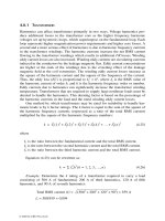
Currents significant enough to cause a shock would flow through the person in
contact with the motor body.
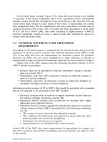
5.3 NATIONAL ELECTRICAL CODE GROUNDING
REQUIREMENTS
Grounding of electrical systems is mandated by the electrical codes that govern the
operation of electrical power systems. The National Electrical Code (NEC) in the
U.S. is the body that lays out requirements for electrical systems for premises.
However, the NEC does not cover installations in ships, railways, or aircraft or
underground in mines or electrical installations under the exclusive control of utilities.
Article 250 of the NEC requires that the following electrical systems of 50 to
1000 V should be grounded:
• Systems that can be grounded so that the maximum voltage to ground
does not exceed 150 V
• Three-phase, four-wire, Wye-connected systems in which the neutral is
used as a circuit conductor
• Three-phase, four-wire,
∆
-connected systems in which the midpoint of
one phase winding is used as a circuit conductor
Alternating current systems of 50 to 1000 V that should be permitted to be grounded
but are not required to be grounded by the NEC include:
• Electrical systems used exclusively to supply industrial electric furnaces
for melting, refining, tempering, and the like
• Separately derived systems used exclusively for rectifiers that supply
adjustable speed industrial drives
• Separately derived systems supplied by transformers that have a primary
voltage rating less than 1000 V, provided all of the following conditions
are met:
• The system is used exclusively for industrial controls.
• The conditions of maintenance and supervision ensure that only qual-
ified personnel will service the installation.
• Continuity of control power is required.
• Ground detectors are installed in the control system.
Article 250 of the NEC also states requirements for grounding for systems less
than 50 V and those rated 1000 V and higher; interested readers are urged to refer
to the Article.
© 2002 by CRC Press LLC
5.4 ESSENTIALS OF A GROUNDED SYSTEM
Figure 5.2 shows the essential elements of a grounded electrical power system. It
is best to have a clear understanding of the components of a ground system to fully
grasp the importance of grounding for safety and power quality. The elements of
Figure 5.2 are defined as follows:
Grounded conductor:
A circuit conductor that is intentionally grounded (for
example, the neutral of a three-phase Wye connected system or the midpoint
of a single-phase 240/120 V system)
Grounding conductor:
A conductor used to connect the grounded circuit of a
system to a grounding electrode or electrodes
Equipment grounding conductor:
Conductor used to connect the non-current-
carrying metal parts of equipment, raceways, and other enclosures to the
system grounded conductor, the grounding electrode conductor, or both at
the service equipment or at the source of a separately derived system
Grounding electrode conductor:
Conductor used to connect the grounding
electrode to the equipment grounding conductor, the grounded conductor,
or both
Main bonding jumper:
An unspliced connection used to connect the equipment
grounding conductor and the service disconnect enclosure to the grounded
conductor of a power system
Ground:
Earth or some conducting body of relatively large extent that serves
in place of the earth
Ground electrode:
A conductor or body of conductors in intimate contact with
the earth for the purpose of providing a connection with the ground
FIGURE 5.2
Main service switchboard indicating elements of a ground system.
MAIN
SERVICE
DISCONNECT
MAIN BONDING
JUMPER
GROUNDING ELECTRODE CONDUCTOR
GROUND ELECTRODE
GROUND ROD, COLD WATER PIPE, BUILDING STEEL
GROUND RING, CONCRETE ENCASED ELECTRODE ETC.
GROUND BUS
PHASE CONDUCTOR
NEUTRAL CONDUCTOR
SOURCE
EQUIPMENT
GROUNDING
CONDUCTOR
(IF PROVIDED)
NEUTRAL BUS (GROUNDED CONDUCTOR)
BRANCH
OVERCURRENT
DEVICES
NEUTRAL DISCONNECT LINK
(GROUNDED CONDUCTOR)
© 2002 by CRC Press LLC
5.5 GROUND ELECTRODES
In this section, various types of ground electrodes and their use will be discussed.
The NEC states that the following elements are part of a ground electrode system
in a facility:
• Metal underground water pipe
• Metal frame of buildings or structures
• Concrete-encased electrodes
• Ground ring
• Other made electrodes, such as underground structures, rod and pipe
electrodes, and plate electrodes, when none of the above-listed items is
available.
The code prohibits the use of a metal underground gas piping system as a ground
electrode. Also, aluminum electrodes are not permitted. The NEC also mentions
that, when applicable, each of the items listed above should be bonded together. The
purpose of this requirement is to ensure that the ground electrode system is large
enough to present low impedance to the flow of fault energy. It should be recognized
that, while any one of the ground electrodes may be adequate by itself, bonding all
of these together provides a superior ground grid system.
Why all this preoccupation with ground systems that are extensive and inter-
connected? The answer is low impedance reference. A facility may have several
individual buildings, each with its own power source. Each building may even have
several power sources, such as transformers, uninterruptible power source (UPS)
units, and battery systems. It is important that the electrical system or systems of
each building become part of the same overall grounding system. A low impedance
ground reference plane results from this arrangement (Figure 5.3). Among the
additional benefits to the creation of a low-impedance earth-ground system is the
fact that when an overhead power line contacts the earth, a low-impedance system
will help produce ground-fault currents of sufficient magnitude to operate the over-
current protection. When electrical charges associated with lightning strike a building
and its electrical system, the lightning energy could pass safely to earth without
damaging electrical equipment or causing injury to people. It is the author’s personal
experience that a lack of attention to grounding and bonding has been responsible
for many preventable accidents involving equipment and personnel.
5.6 EARTH RESISTANCE TESTS
The earth resistance test is a means to ensure that the ground electrode system of a
facility has adequate contact with earth. Figure 5.4 shows how an earth resistance
tester is used to test the resistance between the ground grid and earth. The most
common method of testing earth resistance is the fall of potential test, for which the
earth resistance tester is connected as shown in Figure 5.4. The ground electrode of
the facility or building is used as the reference point. Two ground rods are driven
as indicated. The farthest rod is called the current rod (C
2
), and the rod at the
© 2002 by CRC Press LLC
intermediate point is the potential rod (P
2
). A known current is circulated between
the reference electrode and the current rod. The voltage drop is measured between
the reference ground electrode and the potential rod. The ground resistance is
calculated as the ratio between the voltage and the current. The tester automatically
calculates and displays the resistance in ohms. The potential rod is then moved to
another location and the test repeated. The resistance values are plotted against the
distance from the reference rod. The graph in Figure 5.4 is a typical earth resistance
curve. The earth resistance is represented by the value corresponding to the flat
portion of the curve. In typical ground grid systems, the value at a distance 62% of
the total distance between the reference electrode and the current rod is taken as the
resistance of the ground system with respect to earth.
The distance between the reference electrode and the current rod is determined
by the type and size of the ground grid system. For a single ground rod, a distance
of 100 to 150 ft is adequate. For large ground grid systems consisting of multiple
ground rods, ground rings, or concrete-encased systems, the distance between the
reference ground electrode and the current rod should be 5 to 10 times the diagonal
measure of the ground grid system. The reason is that, as currents are injected into
the earth, electrical fields are set up around the electrodes in the form of shells. To
prevent erroneous results, the two sets of shells around the reference electrode and
the current electrode should not overlap. The greater the distance between the two,
the more accurate the ground resistance test results.
FIGURE 5.3
Low-impedance ground reference, provided by the earth, between several build-
ings in the same facility.
© 2002 by CRC Press LLC
Article 250, Section 250-56, of the NEC code states that a single ground elec-
trode that does not have a resistance of 25
Ω
or less must be augmented by an
additional electrode. Earth resistance of 25
Ω
is adequate for residential and small
commercial buildings. For large buildings and facilities that house sensitive loads,
a resistance value of 10
Ω
is typically specified. For buildings that contain sensitive
loads such as signal, communication, and data-processing equipment, a resistance
of 5
Ω
or less is sometimes specified.
Earth resistance depends on the type of soil, its mineral composition, moisture
content, and temperature. Table 5.2 provides the resistivity of various types of soils;
Table 5.3, the effect of moisture on soil resistivity; and Table 5.4, the effect of
temperature on soil resistivity. The information contained in the tables is used to
illustrate the effect of various natural factors on soil resistivity. Table 5.5 shows the
changes in earth resistance by using multiple ground rods. Note that, to realize the
full benefits of multiple rods, the rods should be spaced an adequate distance apart.
FIGURE 5.4
Ground resistance test instrument and plot of ground resistance and distance.
TABLE 5.2
Resistivities of Common Materials
Material Resistivity Range
(
Ω
-
cm)
Surface soils 100–5000
Clay 200–10,000
Sand and gravel 5000–100,000
Limestone 500–400,000
Shales 500–10,000
Sandstone 2000–200,000
Granite 1,000,000
Tap water 1000–5000
Seawater 20–200
C1 P1 P2 C2
EARTH
RESISTANCE
TESTER
C2P2
REFERENCE
EARTH
L
DISTANCE
L0.62L
R G
RESISTANCE
© 2002 by CRC Press LLC
TABLE 5.3
Effect of Moisture on Soil Resistivity
Moisture Content
(% by weight)
Resistivity (
Ω
-cm)
Top Soil Sandy Loam
0 1000
×
10
6
1000
×
10
6
2.5 250,000 15,000
5 165,000 43,000
10 53,000 22,000
15 21,000 13,000
20 12,000 10,000
30 10,000 8000
TABLE 5.4
Effect of Temperature on Earth
Resistivity
a
Temperature
°C °F Resistivity (
Ω
-cm)
20 68 7200
10 50 9900
0 32 (water) 13,800
0 32 (ice) 30,000
–5 23 79,000
–15 5 330,000
a
For sandy loam, 15.2% moisture.
TABLE 5.5
Change in Earth Resistance with Multiple
Ground Rods
Distance between Rods
a
Number of
Ground Rods
D = L
(%)
D = 2L
(%)
D = 4L
(%)
1 100 — —
2605250
3423735
4352927
5282523
10 16 14 12
a
One ground rod of length L is used as reference.
© 2002 by CRC Press LLC
5.7 EARTH–GROUND GRID SYSTEMS
Ground grids can take different forms and shapes. The ultimate purpose is to provide
a metal grid of sufficient area of contact with the earth so as to derive low resistance
between the ground electrode and the earth. Two of the main requirements of any
ground grid are to ensure that it will be stable with time and that it will not form
chemical reactions with other metal objects in the vicinity, such as buried water
pipes, building reinforcment bars, etc., and cause corrosion either in the ground grid
or the neighboring metal objects.
5.7.1 G
ROUND
R
ODS
According to the NEC, ground rods should be not less than 8 ft long and should
consist of the following:
• Electrodes of conduits or pipes that are no smaller than 3/4-inch trade
size; when these conduits are made of steel, the outer surface should be
galvanized or otherwise metal-coated for corrosion protection
• Electrodes of rods of iron or steel that are at least 5/8 inches in diameter;
the electrodes should be installed so that at least an 8-ft length is in contact
with soil
Typically, copper-clad steel rods are used for ground rods. Steel provides the strength
needed to withstand the forces during driving of the rod into the soil, while the
copper coating provides corrosion protection and also allows copper conductors to
be attached to the ground rod. The values indicated above are the minimum values;
depending on the installation and the type of soil encountered, larger and longer
rods or pipes may be needed. Table 5.6 shows earth resistance variation with the
length of the ground rod, and Table 5.7 shows earth resistance values for ground
rods of various diameters. The values are shown for a soil with a typical ground
resistivity of 10,000
Ω
-cm.
TABLE 5.6
Effect of Ground Rod Length on Earth Resistance
Ground Rod Length (ft) Earth Resistance
(
Ω
)
540
825
10 21
12 18
15 17
Note:
Soil resistivity = 10,000
Ω
-
cm.
© 2002 by CRC Press LLC
5.7.2 P
LATES
Rectangular or circular plates should present an area of at least 2 ft
2
to the soil.
Electrodes of iron and steel shall be at least 1/4 inch in thickness; electrodes of
nonferrous metal should have a minimum thickness of 0.06 inch. Plate electrodes
are to be installed at a minimum distance of 2.5 ft below the surface of the earth.
Table 5.8 gives the earth resistance values for circular plates buried 3 ft below the
surface in soil with a resistivity of 10,000
Ω
-cm.
5.7.3 G
ROUND
R
ING
The ground ring encircling a building in direct contact with the earth should be
installed at a depth of not less than 2.5 ft below the surface of the earth. The ground
ring should consist of at least 20 ft of bare copper conductor sized not less than #2
AWG. Typically, ground rings are installed in trenches around the building, and wire
tails are brought out for connection to the grounded service conductor at the service
disconnect panel or switchboard. It is preferred that a continuous piece of wire be
TABLE 5.7
Effect of Ground Rod Diameter on Earth
Resistance
a
Rod Diameter (inches) % Resistance
0.5 100
0.75 90
1.0 85
1.5 78
2.0 76
Note:
Soil resistivity = 10,000
Ω
-
cm.
a
Resistance of a 0.5-inch-diameter rod is used as reference.
TABLE 5.8
Resistance of Circular Plates Buried 3 Feet
Below Surface
Plate Area (ft
2
) Earth Resistance (
Ω
)
230
423
618
10 15
20 12
Note:
Soil resistivity = 10,000
Ω
-
cm.
© 2002 by CRC Press LLC
used. In large buildings, this might be impractical. If wires are spliced together, the
connections should be made using exothermic welding or listed wire connectors.
Table 5.9 provides the resistance of two conductors buried 3 ft below the surface
for various conductor lengths. The values contained in the table are intended to point
out the variations that may be obtained using different types of earth electrodes. The
values are not to be used for designing ground grids, as the values are apt to change
with the type of soil and soil temperatures at the installation.
5.8 POWER GROUND SYSTEM
A good ground electrode grid system with low resistance to earth is a vital foundation
for the entire power system for the facility. As we mentioned earlier, the primary
objective of power system grounding is personal safety, in addition to limiting
damage to equipment. When a ground fault occurs, large ground return currents are
set up which causes the overcurrent protection to open and isolate the load from the
power source. In many cases, the phase overcurrent protection is depended upon to
perform this function during a ground fault. Article 250-95 of the NEC (1999)
requires ground fault protection for solidly grounded Wye-connected electrical ser-
vices of more than 150 V to ground, not exceeding 600 V phase-to-phase, for each
service rated 1000 A or more. This requirement recognizes the need for ground fault
protection for systems rated greater than 150 V to ground because of the possibility
of arcing ground faults in such systems. Arcing ground faults generate considerably
lower fault currents than bolted ground faults or direct short circuits between phase
and ground. The possibility of arcing ground faults in systems rated less than 150
V to ground should be acknowledged, and ground fault protection against low-level
ground faults should be provided for the power system. The ground fault protection
is set at levels considerably lower than the phase fault protection. For instance, a
1000-A-rated overcurrent protection system may have the ground fault protection
set at 200 A or lower. The setting of the ground fault device depends on the degree
of protection required, as this requirement is strictly ground fault protection for
equipment.
As indicated in Table 5.1, it takes very little current to cause electrical shock
and even loss of life. This is why ground fault circuit interrupters (GFCIs) are
required by the NEC for convenience outlets in certain areas of homes or facilities.
TABLE 5.9
Earth Resistance of Buried Conductors
Wire Size
(AWG)
Resistance (
Ω
) for Total Buried Wire Length
20 ft 40 ft 60 ft 100 ft 200 ft
# 6 23 14 7 5 3
# 1/0 18 12 6 4 2
Note:
Soil resistivity = 10,000
Ω
-
cm.
© 2002 by CRC Press LLC
GFCI protection is set to open a circuit at a current of 5 mA. The GFCI is not
intended for equipment protection but is strictly for personal protection. Figure 5.5
illustrates a typical facility power-grounding scheme.
5.9 SIGNAL REFERENCE GROUND
Signal reference ground
(SRG) is a relatively new term. The main purpose of the
signal reference ground is not personal safety or equipment protection but merely
to provide a common reference low-impedance plane from which sensitive loads
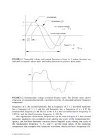
may operate. Why is SRG important? Figure 5.6 depicts two low-level microcircuits
sharing data and power lines. What makes this communication possible is that both
devices have a common reference signal, the ground. If the reference ground is a
high-impedance connection, voltage differentials may be created that would affect
the point of reference for the two devices, so lowering the impedance between the
reference points of the two circuits lowers the potential for coupling of noise between
the devices.
When we mention low impedance, we mean low impedance at high frequencies.
For power frequency, even a few hundred feet of wire can provide adequate imped-
ance, but the situation is different at high frequencies. For example, let us consider
FIGURE 5.5
Typical power system grounding scheme.
© 2002 by CRC Press LLC
a situation when two devices are connected to a 10-ft length of #4 copper conductor
ground wire:
The DC resistance of the wire is = 0.00025
Ω
The inductive reactance at 60 Hz = 0.0012
Ω
Inductive reactance at 1 MHz
≅
20
Ω
If a noise current of 100 mA at 1 MHz is to find its way into the ground wire
between the two devices, the noise voltage must be 2 V, which is enough to cause
the devices to lose communication and perhaps even sustain damage, depending on
the device sensitivity. This example is a simple situation consisting of only two
devices; however, hundreds and perhaps thousands of such devices or circuits might
be present in an actual computer or communication data center. All these devices
require a common reference from which to operate. This is accomplished by the use
of the SRG.
As noted above, the main purpose of the SRG is not electrical safety, even
though nothing that we do to the ground system should compromise safety; rather,
the SRG is a ground plane that provides all sensitive equipment connected to it a
reference point from which to operate without being unduly affected by noise that
may be propagated through the SRG by devices external or internal to the space
protected by the SRG. What we mean by this is that noise may be present in the
SRG, but the presence of the noise should not result in voltage differentials or
current loops of levels that could interfere with the operation of devices that use
the SRG for reference.
FIGURE 5.6
Ground potential difference due to excessive ground impedance.
V
V
in
out
R
G
V
G
© 2002 by CRC Press LLC
The SRG is not a stand-alone entity; it must be bonded to other building ground
electrodes such as building steel, ground ring, or concrete-encased electrodes. This
requirement permits any noise impinging on the SRG to be safely conducted away
from the SRG to building steel and the rest of the ground grid system.
5.10 SIGNAL REFERENCE GROUND METHODS
The SRG can take many forms, depending on the user preference. Some facilities
use a single conductor installed underneath the floor and looped around the space
of the computer center. While this method is practical, it is limited in functionality
due to the large impedances associated with long wires, as mentioned earlier. Larger
computer data centers use more than one conductor but the limitations are the same
as stated above. A preferred SRG consists of #2 AWG or larger copper conductor
laid underneath the floor of the computer or communication center to form a grid
of 2
×
2-ft squares (Figure 5.7). By creating multiple parallel paths, the impedance
for the reference plane is made equal for all devices and circuits sharing the SRG.
If the impedance is measured at any two nodes of the SRG and plotted against
frequency, the shape of the frequency characteristics would appear as shown in
Figure 5.8. The impedance vs. frequency graph should appear the same across any
two sets of nodes of the SRG, as this is the main objective of the SRG.
Some installations use copper strips instead of circular conductors to form the
grid. Other facilities might use sheets of copper under the floor of the computer
center as the SRG. Constructing an SRG with a continuous sheet of copper creates
a reference plane made up of infinite parallel paths instead of a discrete number of
parallel paths as with SRGs made up of circular wires. The SRG is also bonded to
the building steel and the stanchions that support the raised floor of the computer
center. Such an arrangement provides excellent noise immunity and allows the
creation of a good reference plane for the sensitive circuits. Figure 5.9 depicts how
an SRG for a large-sized computer center might be configured. Some installations
use aboveground wiring methods instead of a raised-floor configuration. The prin-
ciple behind the configuration of the SRG does not change whether the ground
FIGURE 5.7
Typical 2
×
2-ft signal reference ground arrangement.
2'
2'
#2 BARE COPPER WIRE
CROSSOVERS
WELDED TOGETHER
OR BOLTED TOGETHER
© 2002 by CRC Press LLC
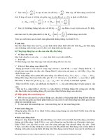
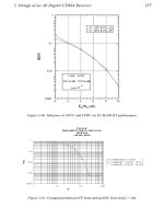
FIGURE 5.8
Typical signal reference ground frequency vs. impedance characteristics.
FIGURE 5.9
Typical computer and communication facility data center grounding and
bonding.
50
40
30
20
10
250K 500K 750K 1M 1.25M 1.5M 1.75M 2M
SRG IMPEDANCE TEST
FREQUENCY V IMPEDANCE
OHMS
FREQUENCY
© 2002 by CRC Press LLC
reference plane is below ground or above ground. It is important that all noise-
producing loads be kept away from the SRG. If such loads are present, they should
be located at the outer periphery of the data center and bonded to the building steel,
if possible.
5.11 SINGLE-POINT AND MULTIPOINT GROUNDING
With multipoint grounding, every piece of equipment sharing a common space or
building is individually grounded (Figure 5.10); whereas, with single-point ground-
ing, each piece of equipment is connected to a common bus or reference plane,
which in turn is bonded to the building ground grid electrode (Figure 5.11). Multi-
point grounding is adequate at power frequencies. For typical power systems, various
transformers, UPS systems, and emergency generators located in each area or floor
of the building are grounded to the nearest building ground electrode, such as
building steel or coldwater pipe. Generally, this method is both convenient and
economical, but it is neither effective nor recommended for grounding sensitive
devices and circuits. As we saw, the primary purpose of grounding for sensitive
equipment is the creation of a reference plane. This is best accomplished by single-
point grounding and bonding means. The SRG must also be bonded to the building
ground electrode to ensure personal safety.
FIGURE 5.10
Multipoint ground system.
BUILDING STEEL
COLD WATER PIPE
GROUND RODS
ABC
D
© 2002 by CRC Press LLC
5.12 GROUND LOOPS
In Chapter 1, a ground loop was defined as a potentially detrimental loop formed
when two or more points in an electrical system that are normally at ground potential
are connected by a conducting path such that either or both points are not at the
same potential. Let’s examine the circuit shown in Figure 5.12. Here, the ground
plane is at different potentials for the two devices that share the ground circuit. This
sets up circulation of currents in the loop formed between the two devices by the
common ground wires and the signal ground conductor. Such an occurrence can
result in performance degradation or damage to devices within the loop. Ground
loops are the result of faulty or improper facility wiring practices that cause stray
currents to flow in the ground path, creating a voltage differential between two points
in the ground system. They may also be due to a high-resistance or high-impedance
connection between a device and the ground plane. Because the signal common or
ground conductor is a low-impedance connection, it only takes a low-level ground
loop potential to cause significant current to flow in the loop. By adhering to sound
ground and bonding practices, as discussed throughout this chapter, ground loop
potentials can be minimized or eliminated.
Problems due to ground loops can be difficult to identify and fix. The author
has observed many instances where well-trained personnel have attempted to fix
FIGURE 5.11
Single-point grounding of sensitive equipment.
ABC
BUILDING
STEEL
COLD WATER
PIPE
GROUND ROD
SYSTEM
SIGNAL GROUND BUS
© 2002 by CRC Press LLC
ground loop problems by removing the ground connections or ground pins from
power and data cords. In all of these cases, relief, if any, has been minimal, and the
conditions created by these actions are nothing short of lethal. This is what we mean
by the statement that nothing that we do to grounding and bonding should make the
installation unsafe.
5.13 ELECTROCHEMICAL REACTIONS
DUE TO GROUND GRIDS
When two dissimilar metals are installed in damp or wet soil, an electrolytic cell
is formed. If there is an external connection between the two metal members, a
current can flow using the electrolyte formed by the wet soil which can cause
deterioration of the anodic (+) member of the metal pair (Figure 5.13). The figure
depicts the copper water pipes and ground rings bonded to the building steel or
reinforcing bars in the foundation. This configuration results in current flow between
the members. Over the course of time, the steel members that are more electrop-
ositive will start to disintegrate as they are asked to supply the electrons to support
the current flow. If not detected, the structural integrity of the building is weakened.
By suitably coating the steel or copper, current flow is interrupted and the electrolytic
action is minimized.
Table 5.10 lists the metals in order of their position in the galvanic series. The
more positive or anodic metals are more active and prone to corrosion. In some
installations, to prevent corrosion of a specific metal member, sacrificial anodes are
installed in the ground. The sacrificial anodes are more electropositive than the
metals they are protecting, so they are sacrificed to protect the structural steel.
FIGURE 5.12
Ground loop voltage and current.
V
AB
COMMON CHASIS GROUND
DUE TO POWER OR SIGNAL
WIRES
GROUND LOOP
VOLTAGE
GROUND
LOOP
CURRENT
© 2002 by CRC Press LLC
5.14 EXAMPLES OF GROUNDING ANOMALIES
OR PROBLEMS
5.14.1 L
OSS
OF
G
ROUND CAUSES FATALITY
Case
At a manufacturing plant that used high-frequency, high-current welders for welding
steel and aluminum parts, one of the welders took a break outdoors on a rainy day.
When he walked back into the building and touched one of the welding machines
to which power was turned on, he collapsed and died of cardiac arrest.
FIGURE 5.13 Metal corrosion due to electrolysis caused by copper and steel in the earth.
TABLE 5.10
Electromotive Series of Metals
Metal Electrode Potential (V)
Magnesium 2.37
Aluminum 1.66
Zinc 0.763
Iron 0.44
Cadmium 0.403
Nickel 0.25
Tin 0.136
Lead 0.126
Copper –0.337
Silver –0.799
Palladium –0.987
Gold –1.5
BUILDING STEEL
ELECTRO-POSITIVE
COPPER PIPE AND GROUND RING
ELECTRO-NEGATIVE
CURRENT FLOW
EARTH (ELECTROLYTE)
© 2002 by CRC Press LLC
Investigation
Figure 5.14 shows the electrical arrangement of the equipment involved in this
incident. The welding machine operated from a 480-V, one-phase source fed from
a 480Y/277 secondary transformer. The input power lines of the machine contained
a capacitance filter to filter high-frequency noise from the load side of the machine
and to keep the noise from being propagated upstream toward the source. The return
current for the welded piece was via the ground lead of the machine. Examination
of the power and ground wiring throughout the building revealed several burned
equipment ground wires. It was determined that due to improper or high-resistance
connections in the return lead of the welder, the current was forced to return through
the equipment ground wire of the machines. The equipment ground wires are not
sized to handle large currents produced by the welding machine. This caused the
equipment ground wire of the machine (and other machines) to be either severely
damaged or totally burned off. As the center point of the capacitive filter is connected
to the frame of the welding machine, the loss of ground caused the frame of the
machine to float and be at a potential higher than the ground. When the operator
touched the machine, he received a shock severe enough to cause cardiac arrest. The
fact that he was exposed to moisture prior to the contact with the machine increased
the severity of the hazard.
5.14.2 STRAY GROUND LOOP CURRENTS CAUSE COMPUTER
D
AMAGE
Case
In a commercial building, computers were burning up at an alarming rate. Most of
the problems were found at the data ports.
Investigation
Wiring problems were found in the electrical panel supplying the computers, such
as with the neutral wires in the ground terminal and ground wires in the neutral
terminal. This configuration caused a portion of the neutral return current of the load
FIGURE 5.14 Example of grounding problem resulting in a fatality.
G
G
NORMAL
RETURN PATH
FOR CURRENT
ALTERNATE
RETURN PATH
FOR CURRENT
SOURCE GROUND
TABLE GROUND
480 V SOURCE
WELDING MACHINE
C
C
FILTER
© 2002 by CRC Press LLC
circuits to return via the equipment ground wires and other grounded parts such as
conduits and water pipes. The current was also high in harmonic content, as would
be expected in such an application. The flow of stray ground currents caused ground
potential differences for the various computers that shared data lines. Resulting
ground loop currents resulted in damage to data ports, which are not designed or
intended to carry such currents. Once the wiring anomalies at the power distribution
panel were corrected, computer damage was not experienced.
5.14.3 GROUND NOISE CAUSES ADJUSTABLE SPEED DRIVES
TO SHUT DOWN
Case
In a newspaper printing facility, two adjustable speed drives (ASDs) were installed
as part of a new conveyor system to transport the finished product to the shipping
area. The ASDs were shutting themselves off periodically, causing papers to back
up on the conveyor and disrupting production.
Investigation
Figure 5.15 depicts the electrical setup of the ASDs. The electrical system in the
facility was relatively old. The drives were supplied from a switchboard located
some distance away. Tests revealed the presence of electrical noise in the lines
supplying the ASDs. Even though the drives contained line filters, they were not
effective in minimizing noise propagation. The conclusion was that the long length
of the ground return wires for the drives presented high impedance to the noise,
thereby allowing it to circulate in the power wiring. To correct the situation, the
ASDs and the filters were bonded to building steel located close to the drives. The
FIGURE 5.15 Adjustable speed drive grounding deficiencies, resulting in shutdowns and
down time, reconfigured to correct the problem.
G
480 VOLT POWER
DISTRIBUTION PANEL
ASD 1
ASD 2
FILTER 2
FILTER 1
UTILITY POWER
TRANSFORMER
BUILDING
STEEL
COLD WATER PIPE
GROUND ROD
M1 M2
© 2002 by CRC Press LLC
building steel was also bonded to the coldwater pipe and ground rods installed for
this section of the power system. This created a good ground reference for the ASDs
and the filter units. Noise was considerably minimized in the power wires. The drives
operated satisfactorily after the changes were implemented.
5.15 CONCLUSIONS
A conclusion that we can draw is that grounding is not an area where one can afford
to be lax. Reference is fundamental to the existence of stability. For electrical
systems, reference is the ground or some other body large enough to serve in place
of the ground, and electrical stability depends on how sound this reference is. We
should not always think of this reference as a ground or a ground connected to the
earth. For the electrical system of a ship, the hull of the ship and the water around
the ship serve as the reference. For aircraft, the fuselage of the aircraft is the
reference. Problems arise when we do not understand what the reference is for a
particular application or we compromise the reference to try to make a system work.
Either condition is a recipe for problems. Grounding is the foundation of any
electrical power, communication, or data-processing system; when the foundation
is taken care of, the rest of the system will be stable.