Crc Press Mechatronics Handbook 2002 By Laxxuss Episode 2 Part 1 potx
Bạn đang xem bản rút gọn của tài liệu. Xem và tải ngay bản đầy đủ của tài liệu tại đây (119.69 KB, 5 trang )
15
The Physical Basis
of Analogies in Physical
System Models
15.1 Introduction
15.2 History
15.3 The Force-Current Analogy: Across
and Through Variables
Drawbacks of the Across-Through
Classification • Measurement as a Basis
for Analogies • Beyond One-Dimensional
Mechanical Systems • Physical Intuition
15.4 Maxwell’s Force-Voltage Analogy:
Effort and Flow Variables
Systems of Particles • Physical Intuition • Dependence
on Reference Frames
15.5 A Thermodynamic Basis for Analogies
Extensive and Intensive Variables • Equilibrium and
Steady State • Analogies, Not Identities • Nodicity
15.6 Graphical Representations
15.7 Concluding Remarks
15.1 Introduction
One of the fascinating aspects of mechatronic systems is that their function depends on interactions
between electrical and mechanical behavior and often magnetic, fluid, thermal, chemical, or other effects
as well. At the same time, this can present a challenge as these phenomena are normally associated with
different disciplines of engineering and physics. One useful approach to this multidisciplinary or “multi-
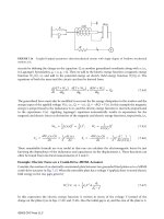
physics” problem is to establish analogies between behavior in different domains—for example, resonance
due to interaction between inertia and elasticity in a mechanical system is analogous to resonance due to
interaction between capacitance and inductance in an electrical circuit. Analogies can provide valuable
insight about how a design works, identify equivalent ways a particular function might be achieved, and
facilitate detailed quantitative analysis. They are especially useful in studying dynamic behavior, which
often arises from interactions between domains; for example, even in the absence of elastic effects, a mass
moving in a magnetic field may exhibit resonant oscillation. However, there are many ways that analogies
may be established and, unfortunately, the most appropriate analogy between electrical circuits, mechan-
ical and fluid systems remains unresolved: is force like current, or is force more like voltage? In this
contribution we examine the physical basis of the analogies in common use and how they may be extended
beyond mechanical and electrical systems.
Neville Hogan
Massachusetts Institute
of Technology
Peter C. Breedveld
University of Twente
©2002 CRC Press LLC
15
The Physical Basis
of Analogies in Physical
System Models
15.1 Introduction
15.2 History
15.3 The Force-Current Analogy: Across
and Through Variables
Drawbacks of the Across-Through
Classification • Measurement as a Basis
for Analogies • Beyond One-Dimensional
Mechanical Systems • Physical Intuition
15.4 Maxwell’s Force-Voltage Analogy:
Effort and Flow Variables
Systems of Particles • Physical Intuition • Dependence
on Reference Frames
15.5 A Thermodynamic Basis for Analogies
Extensive and Intensive Variables • Equilibrium and
Steady State • Analogies, Not Identities • Nodicity
15.6 Graphical Representations
15.7 Concluding Remarks
15.1 Introduction
One of the fascinating aspects of mechatronic systems is that their function depends on interactions
between electrical and mechanical behavior and often magnetic, fluid, thermal, chemical, or other effects
as well. At the same time, this can present a challenge as these phenomena are normally associated with
different disciplines of engineering and physics. One useful approach to this multidisciplinary or “multi-
physics” problem is to establish analogies between behavior in different domains—for example, resonance
due to interaction between inertia and elasticity in a mechanical system is analogous to resonance due to
interaction between capacitance and inductance in an electrical circuit. Analogies can provide valuable
insight about how a design works, identify equivalent ways a particular function might be achieved, and
facilitate detailed quantitative analysis. They are especially useful in studying dynamic behavior, which
often arises from interactions between domains; for example, even in the absence of elastic effects, a mass
moving in a magnetic field may exhibit resonant oscillation. However, there are many ways that analogies
may be established and, unfortunately, the most appropriate analogy between electrical circuits, mechan-
ical and fluid systems remains unresolved: is force like current, or is force more like voltage? In this
contribution we examine the physical basis of the analogies in common use and how they may be extended
beyond mechanical and electrical systems.
Neville Hogan
Massachusetts Institute
of Technology
Peter C. Breedveld
University of Twente
©2002 CRC Press LLC
III
Sensors and
Actuators
16 Introduction to Sensors and Actuators
M. Anjanappa, K. Datta, and T. Song
Sensors • Actuators
17 Fundamentals of Time and Frequency
Michael A. Lombardi
Introduction • Time and Frequency Measurement • Time and Frequency Standards •
Time and Frequency Transfer • Closing
18 Sensor and Actuator Characteristics
Joey Parker
Range • Resolution • Sensitivity • Error • Repeatability • Linearity and
Accuracy • Impedance • Nonlinearities • Static and Coulomb Friction •
Eccentricity • Backlash • Saturation • Deadband • System Response • First-Order
System Response • Underdamped Second-Order System Response • Frequency Response
19 Sensors
Kevin M. Lynch, Michael A. Peshkin, Halit Eren, M. A. Elbestawi,
Ivan J. Garshelis, Richard Thorn, Pamela M. Norris, Bouvard Hosticka,
Jorge Fernando Figueroa, H. R. (Bart) Everett, Stanley S. Ipson, and Chang Liu
Linear and Rotational Sensors • Acceleration Sensors • Force Measurement • Torque and
Power Measurement • Flow Measurement • Temperature Measurements • Distance
Measuring and Proximity Sensors • Light Detection, Image, and Vision
Systems • Integrated Microsensors
20 Actuators
George T C. Chiu, C. J. Fraser, Ramutis Bansevicius, Rymantas
Tadas Tolocka, Massimo Sorli, Stefano Pastorelli, and Sergey Edward Lyshevski
Electromechanical Actuators • Electrical Machines • Piezoelectric Actuators • Hydraulic
and Pneumatic Actuation Systems • MEMS: Microtransducers Analysis, Design, and
Fabrication
©2002 CRC Press LLC
TABLE 16.1
Type of Sensors for Various Measurement Objectives
Sensor Features
Linear/Rotational sensors
Linear/Rotational variable differential
transducer (LVDT/RVDT)
High resolution with wide range capability
Very stable in static and quasi-static applications
Optical encoder Simple, reliable, and low-cost solution
Good for both absolute and incremental measurements
Electrical tachometer Resolution depends on type such as generator or magnetic pickups
Hall effect sensor High accuracy over a small to medium range
Capacitive transducer Very high resolution with high sensitivity
Low power requirements
Good for high frequency dynamic measurements
Strain gauge elements Very high accuracy in small ranges
Provides high resolution at low noise levels
Interferometer Laser systems provide extremely high resolution in large ranges
Very reliable and expensive
Magnetic pickup Output is sinusoidal
Gyroscope
Inductosyn Very high resolution over small ranges
Acceleration sensors
Seismic accelerometer Good for measuring frequencies up to 40% of its natural frequency
Piezoelectric accelerometer High sensitivity, compact, and rugged
Very high natural frequency (100 kHz typical)
Force, torque, and pressure sensor
Strain gauge
Dynamometers/load cells
Good for both static and dynamic measurements
They are also available as micro- and nanosensors
Piezoelectric load cells Good for high precision dynamic force measurements
Tactile sensor Compact, has wide dynamic range, and high
Ultrasonic stress sensor Good for small force measurements
Flow sensors
Pitot tube Widely used as a flow rate sensor to determine speed in aircrafts
Orifice plate Least expensive with limited range
Flow nozzle, venturi tubes Accurate on wide range of flow
More complex and expensive
Rotameter Good for upstream flow measurements
Used in conjunction with variable inductance sensor
Ultrasonic type Good for very high flow rates
Can be used for both upstream and downstream flow measurements
Turbine flow meter Not suited for fluids containing abrasive particles
Relationship between flow rate and angular velocity is linear
Electromagnetic flow meter Least intrusive as it is noncontact type
Can be used with fluids that are corrosive, contaminated, etc.
The fluid has to be electrically conductive
Temperature sensors
Thermocouples This is the cheapest and the most versatile sensor
Applicable over wide temperature ranges (
-
200
∞
C to 1200
∞
C typical)
Thermistors Very high sensitivity in medium ranges (up to 100
∞
C typical)
Compact but nonlinear in nature
Thermodiodes, thermo transistors Ideally suited for chip temperature measurements
Minimized self heating
RTD—resistance temperature detector More stable over a long period of time compared to thermocouple
Linear over a wide range
(
continued
)
©2002 CRC Press LLC
17
Fundamentals of Time
and Frequency
17.1 Introduction
Coordinated Universal Time (UTC)
17.2 Time and Frequency Measurement
Accuracy • Stability
17.3 Time and Frequency Standards
Quartz Oscillators • Rubidium Oscillators
• Cesium Oscillators
17.4 Time and Frequency Transfer
Fundamentals of Time and Frequency Transfer
• Radio Time and Frequency Transfer Signals
17.5 Closing
17.1 Introduction
Time and frequency standards supply three basic types of information:
time-of-day,
time interval
, and
frequency
. Time-of-day information is provided in hours, minutes, and seconds, but often also includes
the
date
(month, day, and year). A device that displays or records time-of-day information is called a
clock
. If a clock is used to label when an event happened, this label is sometimes called a
time tag
or
time
stamp
. Date and time-of-day can also be used to ensure that events are
synchronized
, or happen at the
same time.
Time interval is the duration or elapsed time between two events. The standard unit of time interval
is the second(s). However, many engineering applications require the measurement of shorter time
intervals, such as milliseconds (1 ms
=
10
-
3
s), microseconds (1
µ
s
=
10
-
6
s), nanoseconds (1 ns
=
10
-
9
s),
and picoseconds (1 ps
=
10
-
12
s). Time is one of the seven base physical quantities, and the second is one
of seven base units defined in the International System of Units (SI). The definitions of many other
physical quantities rely upon the definition of the second. The second was once defined based on the
earth’s rotational rate or as a fraction of the tropical year. That changed in 1967 when the era of atomic
time keeping formally began. The current definition of the SI second is:
The duration of 9,192,631,770 periods of the radiation corresponding to the transition between two
hyperfine levels of the ground state of the cesium-133 atom.
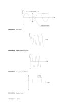
Frequency is the rate of a repetitive event. If
T
is the period of a repetitive event, then the frequency
f
is its reciprocal, 1/
T
. Conversely, the period is the reciprocal of the frequency,
T
=
1/
f
. Since the period
is a time interval expressed in seconds (s), it is easy to see the close relationship between time interval
and frequency. The standard unit for frequency is the hertz (Hz), defined as events or cycles per second.
The frequency of electrical signals is often measured in multiples of hertz, including kilohertz (kHz),
megahertz (MHz), or gigahertz (GHz), where 1 kHz equals one thousand (10
3
) events per second, 1 MHz
Michael A. Lombardi
National Institute of Standards
and Technology
©2002 CRC Press LLC