Machinery''''s Handbook 27th Episode 2 Part 4 doc
Bạn đang xem bản rút gọn của tài liệu. Xem và tải ngay bản đầy đủ của tài liệu tại đây (452.01 KB, 54 trang )
SPEEDS AND FEEDS 1035
Table 5a. Turning-Speed Adjustment Factors for Feed, Depth of Cut, and Lead Angle
Use with Tables 1 through 9. Not for HSS tools. Tables 1 through 9 data, except for HSS tools, are based on depth of cut = 0.1 inch, lead angle = 15 degrees, and tool
life = 15 minutes. For other depths of cut, lead angles, or feeds, use the two feed/speed pairs from the tables and calculate the ratio of desired (new) feed to optimum feed
(largest of the two feeds given in the tables), and the ratio of the two cutting speeds (V
avg
/V
opt
). Use the value of these ratios to find the feed factor F
f
at the intersection
of the feed ratio row and the speed ratio column in the left half of the table. The depth-of-cut factor F
d
is found in the same row as the feed factor in the right half of the
table under the column corresponding to the depth of cut and lead angle. The adjusted cutting speed can be calculated from V = V
opt
× F
f
× F
d
, where V
opt
is the smaller
(optimum) of the two speeds from the speed table (from the left side of the column containing the two feed/speed pairs). See the text for examples.
Table 5b. Tool Life Factors for Turning with Carbides, Ceramics, Cermets, CBN, and Polycrystalline Diamond
Except for HSS speed tools, feeds and speeds given in Tables 1 through 9 are based on 15-minute tool life. To adjust speeds for another tool life, multiply the cutting
speed for 15-minute tool life V
15
by the tool life factor from this table according to the following rules: for small feeds where feed ≤
1
⁄
2
f
opt
, the cutting speed for desired
tool life is V
T
= f
s
× V
15
; for medium feeds where
1
⁄
2
f
opt
< feed <
3
⁄
4
f
opt
, V
T
= f
m
× V
15
; and for larger feeds where
3
⁄
4
f
opt
≤ feed ≤ f
opt
, V
T
= f
l
× V
15
. Here, f
opt
is the largest
(optimum) feed of the two feed/speed values given in the speed tables.
Ratio of
Chosen
Feed to
Optimum
Feed
Ratio of the two cutting speeds given in the tables Depth of Cut and Lead Angle
V
avg
/V
opt
1 in. (25.4 mm) 0.4 in. (10.2 mm) 0.2 in. (5.1 mm) 0.1 in. (2.5 mm) 0.04 in. (1.0 mm)
1.00 1.10 1.25 1.35 1.50 1.75 2.00 15° 45° 15° 45° 15° 45° 15° 45° 15° 45°
Feed Factor, F
f
Depth of Cut and Lead Angle Factor, F
d
1.00 1.0 1.0 1.0 1.0 1.0 1.0 1.0 0.74 1.0 0.79 1.03 0.85 1.08 1.0 1.18 1.29 1.35
0.90 1.00 1.02 1.05 1.07 1.09 1.10 1.12 0.75 1.0 0.80 1.03 0.86 1.08 1.0 1.17 1.27 1.34
0.80 1.00 1.03 1.09 1.10 1.15 1.20 1.25 0.77 1.0 0.81 1.03 0.87 1.07 1.0 1.15 1.25 1.31
0.70 1.00 1.05 1.13 1.22 1.22 1.32 1.43 0.77 1.0 0.82 1.03 0.87 1.08 1.0 1.15 1.24 1.30
0.60 1.00 1.08 1.20 1.25 1.35 1.50 1.66 0.78 1.0 0.82 1.03 0.88 1.07 1.0 1.14 1.23 1.29
0.50 1.00 1.10 1.25 1.35 1.50 1.75 2.00 0.78 1.0 0.82 1.03 0.88 1.07 1.0 1.14 1.23 1.28
0.40 1.00 1.09 1.28 1.44 1.66 2.03 2.43 0.78 1.0 0.84 1.03 0.89 1.06 1.0 1.13 1.21 1.26
0.30 1.00 1.06 1.32 1.52 1.85 2.42 3.05 0.81 1.0 0.85 1.02 0.90 1.06 1.0 1.12 1.18 1.23
0.20 1.00 1.00 1.34 1.60 2.07 2.96 4.03 0.84 1.0 0.89 1.02 0.91 1.05 1.0 1.10 1.15 1.19
0.10 1.00 0.80 1.20 1.55 2.24 3.74 5.84 0.88 1.0 0.91 1.01 0.92 1.03 1.0 1.06 1.10 1.12
Tool Life, T
(minutes)
Turning with Carbides:
Workpiece < 300 Bhn
Turning with Carbides: Workpiece > 300 Bhn;
Turning with Ceramics: Any Hardness
Turning with Mixed Ceramics:
Any Workpiece Hardness
f
s
f
m
f
l
f
s
f
m
f
l
f
s
f
m
f
l
15 1.0 1.0 1.0 1.0 1.0 1.0 1.0 1.0 1.0
45 0.86 0.81 0.76 0.80 0.75 0.70 0.89 0.87 0.84
90 0.78 0.71 0.64 0.70 0.63 0.56 0.82 0.79 0.75
180 0.71 0.63 0.54 0.61 0.53 0.45 0.76 0.72 0.67
Machinery's Handbook 27th Edition
Copyright 2004, Industrial Press, Inc., New York, NY
1036 SPEEDS AND FEEDS
Table 5c. Cutting-Speed Adjustment Factors for Turning with HSS Tools
For use with HSS tool data only from Tables 1 through 9. Adjusted cutting speed V = V
HSS
× F
f
× F
d
,
where V
HSS
is the tabular speed for turning with high-speed tools.
Example 3, Turning:Determine the cutting speed for turning 1055 steel of 175 to 225
Brinell hardness using a hard ceramic insert, a 15° lead angle, a 0.04-inch depth of cut and
0.0075 in./rev feed.
The two feed/speed combinations given in Table 5a for 1055 steel are 15⁄ 1610 and
8⁄2780, corresponding to 0.015 in./rev at 1610 fpm and 0.008 in./rev at 2780 fpm, respec-
tively. In Table 5a, the feed factor F
f
= 1.75 is found at the intersection of the row corre-
sponding to feed/f
opt
= 7.5⁄15 = 0.5 and the column corresponding to V
avg
/V
opt
= 2780⁄1610
= 1.75 (approximately). The depth-of-cut factor F
d
= 1.23 is found in the same row, under
the column heading for a depth of cut = 0.04 inch and lead angle = 15°. The adjusted cutting
speed is V = 1610 × 1.75 × 1.23 = 3466 fpm.
Example 4, Turning:The cutting speed for 1055 steel calculated in Example 3 represents
the speed required to obtain a 15-minute tool life. Estimate the cutting speed needed to
obtain a tool life of 45, 90, and 180 minutes using the results of Example 3.
To estimate the cutting speed corresponding to another tool life, multiply the cutting
speed for 15-minute tool life V
15
by the adjustment factor from the Table 5b, Tool Life Fac-
tors for Turning. This table gives three factors for adjusting tool life based on the feed used,
f
s
for feeds less than or equal to
1
⁄
2
f
opt
,
3
⁄
4
fm
for midrange feeds between
1
⁄
2
and
3
⁄
4
f
opt
and f
l
for
large feeds greater than or equal to
3
⁄
4
f
opt
and less than f
opt
. In Example 3, f
opt
is 0.015 in./rev
and the selected feed is 0.0075 in./rev =
1
⁄
2
f
opt
. The new cutting speeds for the various tool
lives are obtained by multiplying the cutting speed for 15-minute tool life V
15
by the factor
Feed Feed Factor Depth of Cut
Depth-of-Cut
Factor
in. mm
F
f
in. mm
F
d
0.002 0.05 1.50 0.005 0.13 1.50
0.003 0.08 1.50 0.010 0.25 1.42
0.004 0.10 1.50 0.016 0.41 1.33
0.005 0.13 1.44 0.031 0.79 1.21
0.006 0.15 1.34 0.047 1.19 1.15
0.007 0.18 1.25 0.062 1.57 1.10
0.008 0.20 1.18 0.078 1.98 1.07
0.009 0.23 1.12 0.094 2.39 1.04
0.010 0.25 1.08 0.100 2.54 1.03
0.011 0.28 1.04 0.125 3.18 1.00
0.012 0.30 1.00 0.150 3.81 0.97
0.013 0.33 0.97 0.188 4.78 0.94
0.014 0.36 0.94 0.200 5.08 0.93
0.015 0.38 0.91 0.250 6.35 0.91
0.016 0.41 0.88 0.312 7.92 0.88
0.018 0.46 0.84 0.375 9.53 0.86
0.020 0.51 0.80 0.438 11.13 0.84
0.022 0.56 0.77 0.500 12.70 0.82
0.025 0.64 0.73 0.625 15.88 0.80
0.028 0.71 0.70 0.688 17.48 0.78
0.030 0.76 0.68 0.750 19.05 0.77
0.032 0.81 0.66 0.812 20.62 0.76
0.035 0.89 0.64 0.938 23.83 0.75
0.040 1.02 0.60 1.000 25.40 0.74
0.045 1.14 0.57 1.250 31.75 0.73
0.050 1.27 0.55 1.250 31.75 0.72
0.060 1.52 0.50 1.375 34.93 0.71
Machinery's Handbook 27th Edition
Copyright 2004, Industrial Press, Inc., New York, NY
SPEEDS AND FEEDS 1037
for small feeds f
s
from the column for turning with ceramics in Table 5b. These calcula-
tions, using the cutting speed obtained in Example 3, follow.
Depth of cut, feed, and lead angle remain the same as in Example 3. Notice, increasing
the tool life from 15 to 180 minutes, a factor of 12, reduces the cutting speed by only about
one-third of the V
15
speed.
Table 6. Cutting Feeds and Speeds for Turning Copper Alloys
Abbreviations designate: A, annealed; CD, cold drawn.
The combined feed/speed data in this table are based on tool grades (identified in Table 16) as fol-
lows: uncoated carbide, 15; diamond, 9. See the footnote to Table 7.
Tool Life Cutting Speed
15 min
V
15
= 3466 fpm
45 min
V
45
= V
15
× 0.80 = 2773 fpm
90 min
V
90
= V
15
× 0.70 = 2426 fpm
180 min
V
180
= V
15
× 0.61 = 2114 fpm
Group 1
Architectural bronze (C38500); Extra-high-headed brass (C35600); Forging brass (C37700); Free-
cutting phosphor bronze, B2 (C54400); Free-cutting brass (C36000); Free-cutting Muntz metal
(C37000); High-leaded brass (C33200; C34200); High-leaded brass tube (C35300); Leaded com-
mercial bronze (C31400); Leaded naval brass (C48500); Medium-leaded brass (C34000)
Group 2
Aluminum brass, arsenical (C68700); Cartridge brass, 70% (C26000); High-silicon bronze, B
(C65500); Admiralty brass (inhibited) (C44300, C44500); Jewelry bronze, 87.5% (C22600);
Leaded Muntz metal (C36500, C36800); Leaded nickel silver (C79600); Low brass, 80%
(C24000); Low-leaded brass (C33500); Low-silicon bronze, B (C65100); Manganese bronze, A
(C67500); Muntz metal, 60% (C28000); Nickel silver, 55-18 (C77000); Red brass, 85% (C23000);
Yellow brass (C26800)
Group 3
Aluminum bronze, D (C61400); Beryllium copper (C17000, C17200, C17500); Commercial-
bronze, 90% (C22000); Copper nickel, 10% (C70600); Copper nickel, 30% (C71500); Electrolytic
tough pitch copper (C11000); Guilding, 95% (C21000); Nickel silver, 65-10 (C74500); Nickel sil-
ver, 65-12 (C75700); Nickel silver, 65-15 (C75400); Nickel silver, 65-18 (C75200); Oxygen-free
copper (C10200) ; Phosphor bronze, 1.25% (C50200); Phosphor bronze, 10% D (C52400) Phos-
phor bronze, 5% A (C51000); Phosphor bronze, 8% C (C52100); Phosphorus deoxidized copper
(C12200)
Wrought Alloys
Description and UNS
Alloy Numbers
Material
Condition
HSS
Uncoated
Carbide
Polycrystalline
Diamond
Speed
(fpm)
f = feed (0.001 in./rev),
s = speed (ft/min)
Opt. Avg. Opt. Avg.
Group 1
A
CD
300
350
f
s
28
1170
13
1680
Group 2
A
CD
200
250
f
s
28
715
13
900
Group 3
A
CD
100
110
f
s
28
440
13
610
7
1780
13
2080
Machinery's Handbook 27th Edition
Copyright 2004, Industrial Press, Inc., New York, NY
1040 SPEEDS AND FEEDS
Speeds for HSS (high-speed steel) tools are based on a feed of 0.012 inch/rev and a depth of cut of
0.125 inch; use Table 5c to adjust the given speeds for other feeds and depths of cut. The combined
feed/speed data in the remaining columns are based on a depth of cut of 0.1 inch, lead angle of 15
degrees, and nose radius of
3
⁄
64
inch. Use Table 5a to adjust given speeds for other feeds, depths of cut,
and lead angles; use Table 5b to adjust given speeds for increased tool life up to 180 minutes. Exam-
ples are given in the text.
Speed and Feed Tables for Milling.—Tables 10 through 14 give feeds and speeds for
milling. The data in the first speed column can be used with high-speed steel tools using the
feeds given in Table 15a; these are the same speeds contained in previous editions of the
Handbook. The remaining data in Tables 10 through 14 are combined feeds and speeds for
end, face, and slit, slot, and side milling that use the speed adjustment factors given in
Tables 15b, 15c, and 15d. Tool life for the combined feed/speed data can also be adjusted
using the factors in Table 15e. Table 16 lists cutting tool grades and vendor equivalents.
End Milling: Table data for end milling are based on a 3-tooth, 20-degree helix angle tool
with a diameter of 1.0 inch, an axial depth of cut of 0.2 inch, and a radial depth of cut of 1
inch (full slot). Use Table 15b to adjust speeds for other feeds and axial depths of cut, and
Table 15c to adjust speeds if the radial depth of cut is less than the tool diameter. Speeds are
valid for all tool diameters.
Face Milling: Table data for face milling are based on a 10-tooth, 8-inch diameter face
mill, operating with a 15-degree lead angle,
3
⁄
64
-inch nose radius, axial depth of cut = 0.1
inch, and radial depth (width) of cut = 6 inches (i.e., width of cut to cutter diameter ratio =
3
⁄
4
). These speeds are valid if the cutter axis is above or close to the center line of the work-
piece (eccentricity is small). Under these conditions, use Table 15d to adjust speeds for
other feeds and axial and radial depths of cut. For larger eccentricity (i.e., when the cutter
axis to workpiece center line offset is one half the cutter diameter or more), use the end and
side milling adjustment factors (Tables 15b and 15c) instead of the face milling factors.
Slit and Slot Milling: Table data for slit milling are based on an 8-tooth, 10-degree helix
angle tool with a cutter width of 0.4 inch, diameter D of 4.0 inch, and a depth of cut of 0.6
inch. Speeds are valid for all tool diameters and widths. See the examples in the text for
adjustments to the given speeds for other feeds and depths of cut.
Tool life for all tabulated values is approximately 45 minutes; use Table 15e to adjust tool
life from 15 to 180 minutes.
Using the Feed and Speed Tables for Milling: The basic feed for milling cutters is the
feed per tooth (f), which is expressed in inches per tooth. There are many factors to con-
sider in selecting the feed per tooth and no formula is available to resolve these factors.
Among the factors to consider are the cutting tool material; the work material and its hard-
ness; the width and the depth of the cut to be taken; the type of milling cutter to be used and
its size; the surface finish to be produced; the power available on the milling machine; and
the rigidity of the milling machine, the workpiece, the workpiece setup, the milling cutter,
and the cutter mounting.
The cardinal principle is to always use the maximum feed that conditions will permit.
Avoid, if possible, using a feed that is less than 0.001 inch per tooth because such low feeds
reduce the tool life of the cutter. When milling hard materials with small-diameter end
mills, such small feeds may be necessary, but otherwise use as much feed as possible.
Harder materials in general will require lower feeds than softer materials. The width and
the depth of cut also affect the feeds. Wider and deeper cuts must be fed somewhat more
slowly than narrow and shallow cuts. A slower feed rate will result in a better surface fin-
ish; however, always use the heaviest feed that will produce the surface finish desired. Fine
chips produced by fine feeds are dangerous when milling magnesium because spontane-
ous combustion can occur. Thus, when milling magnesium, a fast feed that will produce a
relatively thick chip should be used. Cutting stainless steel produces a work-hardened
layer on the surface that has been cut. Thus, when milling this material, the feed should be
large enough to allow each cutting edge on the cutter to penetrate below the work-hardened
Machinery's Handbook 27th Edition
Copyright 2004, Industrial Press, Inc., New York, NY
SPEEDS AND FEEDS 1041
layer produced by the previous cutting edge. The heavy feeds recommended for face mill-
ing cutters are to be used primarily with larger cutters on milling machines having an ade-
quate amount of power. For smaller face milling cutters, start with smaller feeds and
increase as indicated by the performance of the cutter and the machine.
When planning a milling operation that requires a high cutting speed and a fast feed,
always check to determine if the power required to take the cut is within the capacity of the
milling machine. Excessive power requirements are often encountered when milling with
cemented carbide cutters. The large metal removal rates that can be attained require a high
horsepower output. An example of this type of calculation is given in the section on
Machining Power that follows this section. If the size of the cut must be reduced in order to
stay within the power capacity of the machine, start by reducing the cutting speed rather
than the feed in inches per tooth.
The formula for calculating the table feed rate, when the feed in inches per tooth is
known, is as follows:
where f
m
=milling machine table feed rate in inches per minute (ipm)
f
t
=feed in inch per tooth (ipt)
n
t
=number of teeth in the milling cutter
N=spindle speed of the milling machine in revolutions per minute (rpm)
Example:Calculate the feed rate for milling a piece of AISI 1040 steel having a hardness
of 180 Bhn. The cutter is a 3-inch diameter high-speed steel plain or slab milling cutter
with 8 teeth. The width of the cut is 2 inches, the depth of cut is 0.062 inch, and the cutting
speed from Table 11 is 85 fpm. From Table 15a, the feed rate selected is 0.008 inch per
tooth.
Example 1, Face Milling:Determine the cutting speed and machine operating speed for
face milling an aluminum die casting (alloy 413) using a 4-inch polycrystalline diamond
cutter, a 3-inch width of cut, a 0.10-inch depth of cut, and a feed of 0.006 inch/tooth.
Table 10 gives the feeds and speeds for milling aluminum alloys. The feed/speed pairs
for face milling die cast alloy 413 with polycrystalline diamond (PCD) are 8⁄2320 (0.008
in./tooth feed at 2320 fpm) and 4⁄4755 (0.004 in./tooth feed at 4755 fpm). These speeds are
based on an axial depth of cut of 0.10 inch, an 8-inch cutter diameter D, a 6-inch radial
depth (width) of cut ar, with the cutter approximately centered above the workpiece, i.e.,
eccentricity is low, as shown in Fig. 3. If the preceding conditions apply, the given feeds
and speeds can be used without adjustment for a 45-minute tool life. The given speeds are
valid for all cutter diameters if a radial depth of cut to cutter diameter ratio (ar/D) of
3
⁄
4
is
maintained (i.e.,
6
⁄
8
=
3
⁄
4
). However, if a different feed or axial depth of cut is required, or if
the ar/D ratio is not equal to
3
⁄
4
, the cutting speed must be adjusted for the conditions. The
adjusted cutting speed V is calculated from V = V
opt
× F
f
× F
d
× F
ar
, where V
opt
is the lower
of the two speeds given in the speed table, and F
f
, F
d
, and F
ar
are adjustment factors for
feed, axial depth of cut, and radial depth of cut, respectively, obtained from Table 15d (face
milling); except, when cutting near the end or edge of the workpiece as in Fig. 4, Table 15c
(side milling) is used to obtain F
f
.
f
m
f
t
n
t
N=
N
12V
πD
12 85×
3.14 3×
108 rpm== =
f
m
f
t
n
t
N 0.008 8× 10⁸×==
7 ipm (approximately)=
Machinery's Handbook 27th Edition
Copyright 2004, Industrial Press, Inc., New York, NY
SPEEDS AND FEEDS 1043
The maximum feed f
max
is found in Table 15c by multiplying the optimum feed from the
speed table by the maximum feed factor that corresponds to the ar/D ratio, which in this
instance is 0.02⁄1 = 0.02; the minimum feed f
min
is found by multiplying the optimum feed
by the minimum feed factor. Thus, f
max
= 4.5 × 0.015 = 0.0675 in./tooth and f
min
= 3.1 ×
0.015 = 0.0465 in./tooth. If a feed between these maximum and minimum values is
selected, 0.050 in./tooth for example, then for ar/D = 0.02 and V
avg
/V
opt
= 3.0, the feed fac-
tors at maximum and minimum feeds are F
f1
= 7.90 and F
f2
= 7.01, respectively, and by
interpolation, F
f
= 7.01 + (0.050 − 0.0465)(0.0675 − 0.0465) × (7.90 − 7.01) = 7.16,
approximately 7.2.
The depth of cut factor F
d
is obtained from Table 15b, using f
max
from Table 15c instead
of the optimum feed f
opt
for calculating the feed ratio (chosen feed/optimum feed). In this
example, the feed ratio = chosen feed/f
max
= 0.050⁄0.0675 = 0.74, so the feed factor is F
d
=
0.93 for a depth of cut = 1.0 inch and 0° lead angle. Therefore, the final cutting speed is 80
× 7.2 × 0.93 = 587 ft/min. Notice that f
max
obtained from Table 15c was used instead of the
optimum feed from the speed table, in determining the feed ratio needed to find F
d
.
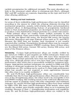
Slit Milling.—The tabular data for slit milling is based on an 8-tooth, 10-degree helix
angle cutter with a width of 0.4 inch, a diameter D of 4.0 inch, and a depth of cut of 0.6 inch.
The given feeds and speeds are valid for any diameters and tool widths, as long as suffi-
cient machine power is available. Adjustments to cutting speeds for other feeds and depths
of cut are made using Table 15c or 15d, depending on the orientation of the cutter to the
work, as illustrated in Case 1 and Case 2 of Fig. 5. The situation illustrated in Case 1 is
approximately equivalent to that illustrated in Fig. 3, and Case 2 is approximately equiva-
lent to that shown in Fig. 4.
Case 1: If the cutter is fed directly into the workpiece, i.e., the feed is perpendicular to the
surface of the workpiece, as in cutting off, then Table 15d (face milling) is used to adjust
speeds for other feeds. The depth of cut portion of Table 15d is not used in this case (F
d
=
1.0), so the adjusted cutting speed V = V
opt
× F
f
× F
ar
. In determining the factor F
ar
from
Table 15d, the radial depth of cut ar is the length of cut created by the portion of the cutter
engaged in the work.
Case 2: If the cutter feed is parallel to the surface of the workpiece, as in slotting or side
milling, then Table 15c (side milling) is used to adjust the given speeds for other feeds. In
Table 15c, the cutting depth (slot depth, for example) is the radial depth of cut ar that is
used to determine maximum and minimum allowable feed/tooth and the feed factor F
f
.
These minimum and maximum feeds are determined in the manner described previously,
however, the axial depth of cut factor F
d
is not required. The adjusted cutting speed, valid
for cutters of any thickness (width), is given by V = V
opt
× F
f
.
Fig. 5. Determination of Radial Depth of Cut or in Slit Milling
Case 1
f
Work
ar
Case 2
f
Slit Mill
feed/rev, f
Chip
Thickness
ar
Machinery's Handbook 27th Edition
Copyright 2004, Industrial Press, Inc., New York, NY
SPEEDS AND FEEDS1046
Plain carbon steels: 1027, 1030,
1033, 1035, 1036, 1037, 1038,
1039, 1040, 1041, 1042, 1043,
1045, 1046, 1048, 1049, 1050,
1052, 1524, 1526, 1527, 1541
125–175 100
f
s
7
35
4
100
39
215
20
405
175–225 85
f
s
7
30
4
85
39
185
20
350
225–275 70
275–325 55
f
s
7
25
4
70
7
210
4
435
7
300
4
560
39
90
20
170
39
175
20
330
39
90
20
235
39
135
20
325
325–375 35
375–425 25
Plain carbon steels: 1055, 1060,
1064, 1065, 1070, 1074, 1078,
1080, 1084, 1086, 1090, 1095,
1548, 1551, 1552, 1561, 1566
125–175 90
f
s
7
30
4
85
7
325
4
565
7
465
4
720
39
140
20
220
39
195
20
365
39
170
20
350
39
245
20
495
175–225 75
225–275 60
f
s
7
30
4
85
39
185
20
35
0
275–325 45
f
s
7
25
4
70
7
210
4
435
7
300
4
560
39
90
20
170
39
175
20
330
39
90
20
235
39
135
20
325
325–375 30
375–425 15
Free-machining alloy steels
(Resulfurized): 4140, 4150
175–200 100
f
s
15
7
8
30
15
105
8
270
15
270
8
450
39
295
20
475
39
135
20
305
7
25
4
70
200–250 90
250–300 60
f
s
15
6
8
25
15
50
8
175
15
85
8
255
39
200
20
320
39
70
20
210
7
25
4
70
300–375 45
f
s
15
5
8
20
15
40
8
155
15
75
8
22
5
39
175
20
280
375–425 35
Table 11. (Continued) Cutting Feeds and Speeds for Milling Plain Carbon and Alloy Steels
Material
Brinell
Hardness
HSS
End Milling Face Milling Slit Milling
HSS Uncoated Carbide Coated Carbide Uncoated Carbide Coated Carbide Uncoated Carbide Coated Carbide
Speed
(fpm)
f = feed (0.001 in./tooth), s = speed (ft/min)
Opt. Avg. Opt. Avg. Opt. Avg. Opt. Avg. Opt. Avg. Opt. Avg. Opt. Avg.
Machinery's Handbook 27th Edition
Copyright 2004, Industrial Press, Inc., New York, NY
SPEEDS AND FEEDS 1047
Free-machining alloy steels
(Leaded): 41L30, 41L40, 41L47,
41L50, 43L47, 51L32, 52L100,
86L20, 86L40
150–200 115
f
s
7
30
4
85
7
325
4
565
7
465
4
720
39
140
20
220
39
195
20
365
39
170
20
350
39
245
20
495
200–250 95
f
s
7
30
4
85
39
185
20
350
250–300 70
f
s
7
25
4
70
7
210
4
435
7
300
4
560
39
90
20
170
39
175
20
330
39
90
20
235
39
135
20
325
300–375 50
375–425 40
Alloy steels: 4012, 4023, 4024,
4028, 4118, 4320, 4419, 4422,
4427, 4615, 4620, 4621, 4626,
4718, 4720, 4815, 4817, 4820,
5015, 5117, 5120, 6118, 8115,
8615, 8617, 8620, 8622, 8625,
8627, 8720, 8822, 94B17
125–175 100
f
s
15
7
8
30
15
105
8
270
15
220
8
450
39
295
20
475
39
135
20
305
39
26
5
20
495
175–225 90
225–275 60
f
s
15
6
8
25
15
50
8
175
15
85
8
255
39
200
20
320
39
70
20
210
39
115
20
290
275–325 50
f
s
15
5
8
20
15
45
8
170
15
80
8
240
39
190
20
305
325–375 40
f
s
15
5
8
20
15
40
8
155
15
75
8
225
39
175
20
280
375–425 25
Alloy steels: 1330, 1335, 1340,
1345, 4032, 4037, 4042, 4047,
4130, 4135, 4137, 4140, 4142,
4145, 4147, 4150, 4161, 4337,
4340, 50B44, 50B46, 50B50,
50B60, 5130, 5132, 5140, 5145,
5147, 5150, 5160, 51B60, 6150,
81B45, 8630, 8635, 8637, 8640,
8642, 8645, 8650, 8655, 8660,
8740, 9254, 9255, 9260, 9262,
94B30
E51100, E52100: use (HSS
speeds)
175–225 75 (65)
f
s
15
5
8
30
15
105
8
270
15
220
8
450
39
295
20
475
39
135
20
305
39
265
20
495
225–275 60
f
s
15
5
8
25
15
50
8
17
5
15
85
8
255
39
200
20
320
39
70
20
210
39
115
20
290
275–325 50 (40)
f
s
15
5
8
25
15
45
8
170
15
80
8
240
39
190
20
305
325–375 35 (30)
f
s
15
5
8
20
15
40
8
155
15
75
8
225
39
175
20
280
375–425 20
Table 11. (Continued) Cutting Feeds and Speeds for Milling Plain Carbon and Alloy Steels
Material
Brinell
Hardness
HSS
End Milling Face Milling Slit Milling
HSS Uncoated Carbide Coated Carbide Uncoated Carbide Coated Carbide Uncoated Carbide Coated Carbide
Speed
(fpm)
f = feed (0.001 in./tooth), s = speed (ft/min)
Opt. Avg. Opt. Avg. Opt. Avg. Opt. Avg. Opt. Avg. Opt. Avg. Opt. Avg.
Machinery's Handbook 27th Edition
Copyright 2004, Industrial Press, Inc., New York, NY
SPEEDS AND FEEDS1048
For HSS (high-speed steel) tools in the first speed column only, use Table 15a for recommended feed in inches per tooth and depth of cut.
End Milling: Table data for end milling are based on a 3-tooth, 20-degree helix angle tool with a diameter of 1.0 inch, an axial depth of cut of 0.2 inch, and a radial
depth of cut of 1 inch (full slot). Use Table 15b to adjust speeds for other feeds and axial depths of cut, and Table 15c to adjust speeds if the radial depth of cut is less than
the tool diameter. Speeds are valid for all tool diameters.
Face Milling: Table data for face milling are based on a 10-tooth, 8-inch diameter face mill, operating with a 15-degree lead angle,
3
⁄
64
-inch nose radius, axial depth of
cut = 0.1 inch, and radial depth (width) of cut = 6 inches (i.e., width of cut to cutter diameter ratio =
3
⁄
4
). These speeds are valid if the cutter axis is above or close to the
center line of the workpiece (eccentricity is small). Under these conditions, use Table 15d to adjust speeds for other feeds and axial and radial depths of cut. For larger
eccentricity (i.e., when the cutter axis to workpiece center line offset is one half the cutter diameter or more), use the end and side milling adjustment factors (Tables 15b
and 15c) instead of the face milling factors.
Slit and Slot Milling: Table data for slit milling are based on an 8-tooth, 10-degree helix angle tool with a cutter width of 0.4 inch, diameter D of 4.0 inches, and a depth
of cut of 0.6 inch. Speeds are valid for all tool diameters and widths. See the examples in the text for adjustments to the given speeds for other feeds and depths of cut.
Tool life for all tabulated values is approximately 45 minutes; use Table 15e to adjust tool life from 15 to 180 minutes. The combined feed/speed data in this table are
based on tool grades (identified in Table 16) as follows: end and slit milling uncoated carbide = 20 except † = 15; face milling uncoated carbide = 19; end, face, and slit
milling coated carbide = 10.
Ultra-high-strength steels (not
AISI): AMS 6421 (98B37 Mod.),
6422 (98BV40), 6424, 6427,
6428, 6430, 6432, 6433, 6434,
6436, and 6442; 300M, D6ac
220–300 60
f
s
8
165
4
355
8
300
4
480
300–350 45
350–400 20
f
s
8
15
4
45
8
150
4
320
39
130
20
235
39
75
20
175
43–52 Rc —
f
s
5
20†
3
55
39
5
20
15
Maraging steels (not AISI): 18% Ni
Grades 200, 250, 300, and 350
250–325 50
f
s
8
165
4
355
8
300
4
480
50–52 Rc —
f
s
5
20†
3
55
39
5
20
15
Nitriding steels (not AISI): Nitralloy
125, 135, 135 Mod., 225, and 230,
Nitralloy N, Nitralloy EZ, Nitrex 1
200–250 60
f
s
15
7
8
30
15
105
8
270
15
220
8
450
39
295
20
475
39
135
20
305
39
265
20
495
300–350 25
f
s
15
5
8
20
15
40
8
15
5
15
75
8
225
39
175
20
280
Table 11. (Continued) Cutting Feeds and Speeds for Milling Plain Carbon and Alloy Steels
Material
Brinell
Hardness
HSS
End Milling Face Milling Slit Milling
HSS Uncoated Carbide Coated Carbide Uncoated Carbide Coated Carbide Uncoated Carbide Coated Carbide
Speed
(fpm)
f = feed (0.001 in./tooth), s = speed (ft/min)
Opt. Avg. Opt. Avg. Opt. Avg. Opt. Avg. Opt. Avg. Opt. Avg. Opt. Avg.
Machinery's Handbook 27th Edition
Copyright 2004, Industrial Press, Inc., New York, NY
SPEEDS AND FEEDS 1049
Table 12. Cutting Feeds and Speeds for Milling Tool Steels
Material
Brinell
Hardness
HSS
End Milling Face Milling Slit Milling
HSS
Uncoated
Carbide
Coated
Carbide
Uncoated
Carbide CBN
Uncoated
Carbide
Coated
Carbide
Speed
(fpm)
f = feed (0.001 in./tooth), s = speed (ft/min)
Opt. Avg. Opt. Avg. Opt. Avg. Opt. Avg. Opt. Avg. Opt. Avg. Opt. Avg.
Water hardening: W1, W2, W5 150–200 85
f
s
8
25
4
70
8
235
4
455
8
405
4
635
39
235
20
385
39
115
20
265
39
245
20
445
Shock resisting: S1, S2, S5, S6, S7 175–225 55
Cold work, oil hardening: O1, O2,
O6, O7
175–225 50
Cold work, high carbon, high chro-
mium: D2, D3, D4, D5, D7
200–250 40
Cold work, air hardening: A2,
A3, A8, A9, A10
{ 200–250 50
f
s
39
255
20
385
A4, A6 200–250 45
A7 225–275 40
Hot work, chromium type: H10,
H11, H12, H13, H14, H19
150–200 60
200–250 50
325–375 30
f
s
8
15
4
45
8
150
4
320
39
130
20
235
39
75
20
175
48–50 Rc —
f
s
5
20†
3
55
39
50
20
135
39
5†
20
15
50
–52 Rc —
52–56 Rc —
Hot work, tungsten and molybde-
num types: H21, H22, H23, H24,
H25, H26, H41, H42, H43
150–200 55
f
s
39
255
20
385
200–250 45
Special-purpose, low alloy: L2, L3,
L6
150–200 65
f
s
8
25
4
70
8
235
4
455
8
405
4
635
39
235
20
385
39
115
20
265
39
245
20
445
Mold: P2, P3, P4, P5, P6 P20, P21
100–150 75
150–200 60
High-speed steel: M1, M2, M6,
M10, T1, T2, T6
200–250 50
M3-1, M4, M7, M30, M33, M34,
M36, M41, M42, M43, M44,
M46, M47, T5, T8
{ 225–275 40
f
s
39
255
20
385
T15, M3-2 225–275 30
Machinery's Handbook 27th Edition
Copyright 2004, Industrial Press, Inc., New York, NY
SPEEDS AND FEEDS1050
For HSS (high-speed steel) tools in the first speed column only, use Table 15a for recommended feed in inches per tooth and depth of cut.
End Milling: Table data for end milling are based on a 3-tooth, 20-degree helix angle tool with a diameter of 1.0 inch, an axial depth of cut of 0.2 inch, and a radial
depth of cut of 1 inch (full slot). Use Table 15b to adjust speeds for other feeds and axial depths of cut, and Table 15c to adjust speeds if the radial depth of cut is less than
the tool diameter. Speeds are valid for all tool diameters.
Face Milling: Table data for face milling are based on a 10-tooth, 8-inch diameter face mill, operating with a 15-degree lead angle,
3
⁄
64
-inch nose radius, axial depth of
cut = 0.1 inch, and radial depth (width) of cut = 6 inches (i.e., width of cut to cutter diameter ratio =
3
⁄
4
). These speeds are valid if the cutter axis is above or close to the
center line of the workpiece (eccentricity is small). Under these conditions, use Table 15d to adjust speeds for other feeds and axial and radial depths of cut. For larger
eccentricity (i.e., when the cutter axis to workpiece center line offset is one half the cutter diameter or more), use the end and side milling adjustment factors (Tables 15b
and 15c) instead of the face milling factors.
Slit and Slot Milling: Table data for slit milling are based on an 8-tooth, 10-degree helix angle tool with a cutter width of 0.4 inch, diameter D of 4.0 inches, and a depth
of cut of 0.6 inch. Speeds are valid for all tool diameters and widths. See the examples in the text for adjustments to the given speeds for other feeds and depths of cut.
Tool life for all tabulated values is approximately 45 minutes; use Table 15e to adjust tool life from 15 to 180 minutes. The combined feed/speed data in this table are
based on tool grades (identified in Table 16) as follows: uncoated carbide = 20, † = 15; coated carbide = 10; CBN = 1.
Table 13. Cutting Feeds and Speeds for Milling Stainless Steels
Material
Brinell
Hardness
HSS
End Milling Face Milling Slit Milling
HSS
Uncoated
Carbide
Coated
Carbide
Coated
Carbide
Uncoated
Carbide
Coated
Carbide
Speed
(fpm)
f = feed (0.001 in./tooth), s = speed (ft/min)
Opt. Avg. Opt. Avg. Opt. Avg. Opt. Avg. Opt. Avg. Opt. Avg.
Free-machining stainless steels (Ferritic): 430F,
430FSe
135–185 110
f
s
7
30
4
80
7
305
4
780
7
420
4
1240
39
210
20
385
39
120
20
345
39
155
20
475
(Austenitic): 203EZ, 303, 303Se, 303MA,
303Pb, 303Cu, 303 Plus X
{
135–185 100
f
s
7
20
4
55
7
210
4
585
39
75
20
240
225–275 80
(Martensitic): 416, 416Se, 416 Plus X, 420F,
420FSe, 440F, 440FSe
{
135–185 110
185–240 100
275–325 60
375–425 30
Stainless steels (Ferritic): 405, 409, 429, 430,
434, 436, 442, 446, 502
135–185 90
f
s
7
30
4
80
7
305
4
780
7
420
4
1240
39
210
20
385
39
120
20
345
39
15
5
20
475
(Austenitic): 201, 202, 301, 302, 304, 304L,
305, 308, 321, 347, 348
{
135–185 75
f
s
7
20
4
55
7
210
4
585
39
75
20
240
225–275 65
(Austenitic): 302B, 309, 309S, 310,
310S, 314, 316, 316L, 317, 330
135–185 70
(Martensitic): 403, 410, 420, 501 {
135–175 95
175–225 85
275–325 55
375–425 35
Machinery's Handbook 27th Edition
Copyright 2004, Industrial Press, Inc., New York, NY
SPEEDS AND FEEDS 1051
For HSS (high-speed steel) tools in the first speed column only, use Table 15a for recommended feed in inches per tooth and depth of cut.
End Milling: Table data for end milling are based on a 3-tooth, 20-degree helix angle tool with a diameter of 1.0 inch, an axial depth of cut of 0.2 inch, and a radial
depth of cut of 1 inch (full slot). Use Table 15b to adjust speeds for other feeds and axial depths of cut, and Table 15c to adjust speeds if the radial depth of cut is less than
the tool diameter. Speeds are valid for all tool diameters.
Face Milling: Table data for face milling are based on a 10-tooth, 8-inch diameter face mill, operating with a 15-degree lead angle,
3
⁄
64
-inch nose radius, axial depth of
cut = 0.1 inch, and radial depth (width) of cut = 6 inches (i.e., width of cut to cutter diameter ratio =
3
⁄
4
). These speeds are valid if the cutter axis is above or close to the
center line of the workpiece (eccentricity is small). Under these conditions, use Table 15d to adjust speeds for other feeds and axial and radial depths of cut. For larger
eccentricity (i.e., when the cutter axis to workpiece center line offset is one half the cutter diameter or more), use the end and side milling adjustment factors (Tables 15b
and 15c) instead of the face milling factors.
Slit and Slot Milling: Table data for slit milling are based on an 8-tooth, 10-degree helix angle tool with a cutter width of 0.4 inch, diameter D of 4.0 inch, and a depth
of cut of 0.6 inch. Speeds are valid for all tool diameters and widths. See the examples in the text for adjustments to the given speeds for other feeds and depths of cut.
Tool life for all tabulated values is approximately 45 minutes; use Table 15e to adjust tool life from 15 to 180 minutes. The combined feed/speed data in this table are
based on tool grades (identified in Table 16) as follows: uncoated carbide = 20; coated carbide = 10.
Stainless Steels (Martensitic): 414, 431,
Greek Ascoloy, 440A, 440B, 440C
{
225–275 55–60
275–325 45–50
375–425 30
(Precipitation hardening): 15-5PH, 17-4PH, 17-
7PH, AF-71, 17-14CuMo, AFC-77, AM-350,
AM-355, AM-362, Custom 455, HNM, PH13-
8, PH14-8Mo, PH15-7Mo, Stainless W
150–200 60
f
s
7
20
4
55
7
210
4
585
39
75
20
240
275–325 50
325–375 40
375–450 25
Table 13. (Continued) Cutting Feeds and Speeds for Milling Stainless Steels
Material
Brinell
Hardness
HSS
End Milling Face Milling Slit Milling
HSS
Uncoated
Carbide
Coated
Carbide
Coated
Carbide
Uncoated
Carbide
Coated
Carbide
Speed
(fpm)
f = feed (0.001 in./tooth), s = speed (ft/min)
Opt. Avg. Opt. Avg. Opt. Avg. Opt. Avg. Opt. Avg. Opt. Avg.
Machinery's Handbook 27th Edition
Copyright 2004, Industrial Press, Inc., New York, NY
SPEEDS AND FEEDS 1053
For HSS (high-speed steel) tools in the first speed column only, use Table 15a for recommended feed in inches per tooth and depth of cut.
End Milling: Table data for end milling are based on a 3-tooth, 20-degree helix angle tool with a diameter of 1.0 inch, an axial depth of cut of 0.2 inch, and a radial
depth of cut of 1 inch (full slot). Use Table 15b to adjust speeds for other feeds and axial depths of cut, and Table 15c to adjust speeds if the radial depth of cut is less than
the tool diameter. Speeds are valid for all tool diameters.
Face Milling: Table data for face milling are based on a 10-tooth, 8-inch diameter face mill, operating with a 15-degree lead angle,
3
⁄
64
-inch nose radius, axial depth of
cut = 0.1 inch, and radial depth (width) of cut = 6 inches (i.e., width of cut to cutter diameter ratio =
3
⁄
4
). These speeds are valid if the cutter axis is above or close to the
center line of the workpiece (eccentricity is small). Under these conditions, use Table 15d to adjust speeds for other feeds and axial and radial depths of cut. For larger
eccentricity (i.e., when the cutter axis to workpiece center line offset is one half the cutter diameter or more), use the end and side milling adjustment factors (Tables 15b
and 15c) instead of the face milling factors.
Slit and Slot Milling: Table data for slit milling are based on an 8-tooth, 10-degree helix angle tool with a cutter width of 0.4 inch, diameter D of 4.0 inches, and a depth
of cut of 0.6 inch. Speeds are valid for all tool diameters and widths. See the examples in the text for adjustments to the given speeds for other feeds and depths of cut.
Tool life for all tabulated values is approximately 45 minutes; use Table 15e to adjust tool life from 15 to 180 minutes. The combined feed/speed data in this table are
based on tool grades (identified in Table 16) as follows: uncoated carbide = 15 except † = 20; end and slit milling coated carbide = 10; face milling coated carbide = 11
except ‡ = 10. ceramic = 6; CBN = 1.
Cast Steels
(Low carbon): 1010, 1020 100–150 100
f
s
7
25
4
70
7
245†
4
410
7
420
4
650
39
265‡
20
430
39
135†
20
260
39
245
20
450
(Medium carbon): 1030, 1040 1050 {
125–175 95
175–225 80
f
s
7
20
4
55
7
160†
4
400
7
345
4
560
39
205‡
20
340
39
65†
20
180
39
180
20
370
225–300 60
150–200 85
(Low-carbon alloy): 1320, 2315, 2320,
4110, 4120, 4320, 8020, 8620
{
200–250 75
250–300 50
(Medium-carbon alloy): 1330, 1340,
2325, 2330, 4125, 4130, 4140, 4330,
4340, 8030, 80B30, 8040, 8430, 8440,
8630, 8640, 9525, 9530, 9535
{
175–225 70
f
s
7
15
4
45
7
120†
4
310
39
45†
20
135
225–250 65
250–300 50
f
s
39
25
20
40
300–350 30
Table 14. (Continued) Cutting Feeds and Speeds for Milling Ferrous Cast Metals
Material
Brinell
Hardness
HSS
End Milling Face Milling Slit Milling
HSS
Uncoated
Carbide
Coated
Carbide
Uncoated
Carbide
Coated
Carbide Ceramic CBN
Uncoated
Carbide
Coated
Carbide
Speed
(fpm)
f = feed (0.001 in./tooth), s = speed (ft/min)
Opt. Avg. Opt. Avg. Opt. Avg. Opt. Avg. Opt. Avg. Opt. Avg. Opt. Avg. Opt. Avg. Opt. Avg.
Machinery's Handbook 27th Edition
Copyright 2004, Industrial Press, Inc., New York, NY
SPEEDS AND FEEDS 1055
Pearlitic-Martensitic malleable iron
160–200 .001 .003 .004 .001 .002 .003 .004 .003–.010 .004 .004–.012 .002–.018
200–240 .001 .002 .003 .001 .002 .003 .003 .003–.007 .004 .003–.010 .002–.006
240–300 .001 .002 .002 .001 .001 .002 .002 .002–.006 .003 .002–.008 .002–.005
Cast steel
100–180 .001 .003 .003 .001 .002 .003 .004 .003–.008 .004 .003–.012 .002–.008
180–240 .001 .002 .003 .001 .002 .003 .003 .003–.008 .004 .003–.010 .002–.006
240–300 .001 .002 .002 .005 .002 .002 .002 .002–.006 .003 .003–.008 .002–.005
Zinc alloys (die castings) … .002 .003 .004 .001 .003 .004 .006 .003–.010 .005 .004–.015 .002–.012
Copper alloys (brasses & bronzes)
100–150 .002 .004 .005 .002 .003 .005 .006 .003–.015 .004 .004–.020 .002–.010
150–250 .002 .003 .004 .001 .003 .004 .005 .003–.015 .004 .003–.012 .002–.008
Free cutting brasses & bronzes 80–100 .002 .004 .005 .002 .003 .005 .006 .003–.015 .004 .004–.015 .002–.010
Cast aluminum alloys—as cast … .003 .004 .005 .002 .004 .005 .006 .005–.016 .006 .005–.020 .004–.012
Cast aluminum alloys—hardened … .003 .004 .005 .002 .003 .004 .005 .004–.012 .005 .005–.020 .004–.012
Wrought aluminum alloys— cold drawn … .003 .004 .005 .002 .003 .004 .005 .004–.014 .005 .005–.020 .004–.012
Wrought aluminum alloys—hardened … .002 .003 .004 .001 .002 .003 .004 .003–.012 .004 .005–.020 .004–.012
Magnesium alloys … .003 .004 .005 .003 .004 .005 .007 .005–.016 .006 .008–.020 .005–.012
Ferritic stainless steel 135–185 .001 .002 .003 .001 .002 .003 .003 .002–.006 .004 .004–.008 .002–.007
Austenitic stainless steel
135–185 .001 .002 .003 .001 .002 .003 .003 .003–.007 .004 .005–.008 .002–.007
185–275 .001 .002 .003 .001 .002 .002 .002 .003–.006 .003 .004–.006 .002–.007
Martensitic stainless steel
135–185 .001 .002 .002 .001 .002 .003 .003 .003–.006 .004 .004–.010 .002–.007
185–225 .001 .002 .002 .001 .002 .002 .003 .003–.006 .004 .003–.008 .002–.007
225–300 .0005 .002 .002 .0005 .001 .002 .002 .002–.005 .003 .002–.006 .002–.005
Monel 100–160 .001 .003 .004 .001 .002 .003 .004 .002–.006 .004 .002–.008 .002–.006
Table 15a. (Continued) Recommended Feed in Inches per Tooth (f
t
) for Milling with High Speed Steel Cutters
Material(Continued)
Hard-
ness,
HB
End Mills
Plain
or
Slab
Mills
Form
Relieved
Cutters
Face Mills
and
Shell End
Mills
Slotting
and
Side
Mills
Depth of Cut, .250 in Depth of Cut, .050 in
Cutter Diam., in Cutter Diam., in
1
⁄
2
3
⁄
4
1 and up
1
⁄
4
1
⁄
2
3
⁄
4
1 and up
Feed per Tooth, inch
Machinery's Handbook 27th Edition
Copyright 2004, Industrial Press, Inc., New York, NY
1060 SPEEDS AND FEEDS
Using the Feed and Speed Tables for Drilling, Reaming, and Threading.—The first
two speed columns in Tables 17 through 23 give traditional Handbook speeds for drilling
and reaming. The following material can be used for selecting feeds for use with the tradi-
tional speeds.
The remaining columns in Tables 17 through 23 contain combined feed/speed data for
drilling, reaming, and threading, organized in the same manner as in the turning and mill-
ing tables. Operating at the given feeds and speeds is expected to result in a tool life of
approximately 45 minutes, except for indexable insert drills, which have an expected tool
life of approximately 15 minutes per edge. Examples of using this data follow.
Adjustments to HSS drilling speeds for feed and diameter are made using Table 22;
Table 5a is used for adjustments to indexable insert drilling speeds, where one-half the drill
diameter D is used for the depth of cut. Tool life for HSS drills, reamers, and thread chasers
and taps may be adjusted using Table 15e and for indexable insert drills using Table 5b.
The feed for drilling is governed primarily by the size of the drill and by the material to be
drilled. Other factors that also affect selection of the feed are the workpiece configuration,
the rigidity of the machine tool and the workpiece setup, and the length of the chisel edge.
A chisel edge that is too long will result in a very significant increase in the thrust force,
which may cause large deflections to occur on the machine tool and drill breakage.
For ordinary twist drills, the feed rate used is 0.001 to 0.003 in /rev for drills smaller than
1
⁄
8
in, 0.002 to 0.006 in./rev for
1
⁄
8
- to
1
⁄
4
-in drills; 0.004 to 0.010 in./rev for
1
⁄
4
- to
1
⁄
2
-in drills;
0.007 to 0.015 in./rev for
1
⁄
2
- to 1-in drills; and, 0.010 to 0.025 in./rev for drills larger than 1
inch.
The lower values in the feed ranges should be used for hard materials such as tool steels,
superalloys, and work-hardening stainless steels; the higher values in the feed ranges
should be used to drill soft materials such as aluminum and brass.
Example 1, Drilling:Determine the cutting speed and feed for use with HSS drills in
drilling 1120 steel.
Table 15a gives two sets of feed and speed parameters for drilling 1120 steel with HSS
drills. These sets are 16⁄50 and 8⁄95, i.e., 0.016 in./rev feed at 50 ft/min and 0.008 in./rev at
95 fpm, respectively. These feed/speed sets are based on a 0.6-inch diameter drill. Tool life
for either of the given feed/speed settings is expected to be approximately 45 minutes.
For different feeds or drill diameters, the cutting speeds must be adjusted and can be
determined from V = V
opt
× F
f
× F
d
, where V
opt
is the minimum speed for this material given
in the speed table (50 fpm in this example) and F
f
and F
d
are the adjustment factors for feed
and diameter, respectively, found in Table 22.
Machinery's Handbook 27th Edition
Copyright 2004, Industrial Press, Inc., New York, NY
SPEEDS AND FEEDS1062
Plain carbon steels (Continued): 1055, 1060, 1064,
1065, 1070, 1074, 1078, 1080, 1084, 1086, 1090,
1095, 1548, 1551, 1552, 1561, 1566
{
125–175 85 55
f
s
16
50
8
95
8
370
4
740
27
105
14
115
83
90
20
115
175–225 70 45
225–275 50 30
f
s
8
365
4
735
275–325 40 25
325–375 30 20
375–425 15 10
Free-machining alloy steels (Resulfurized): 4140,
4150
{
175–200 90 60
f
s
16
75
8
140
8
410
4
685
26
150
13
160
83
125
20
160
200–250 80 50
250–300 55 30
f
s
8
355
4
600
300–375 40 25
f
s
8
310
4
525
375–425 30 15
(Leaded): 41L30, 41L40, 41L47, 41L50, 43L47,
51L32, 52L100, 86L20, 86L40
{
150–200 100 65
f
s
16
50
8
95
8
370
4
740
27
105
14
115
83
90
20
115
200–250 90 60
f
s
8
365
4
735
25
0–300 65 40
300–375 45 30
375–425 30 15
Alloy steels: 4012, 4023, 4024, 4028, 4118, 4320,
4419, 4422, 4427, 4615, 4620, 4621, 4626, 4718,
4720, 4815, 4817, 4820, 5015, 5117, 5120, 6118,
8115, 8615, 8617, 8620, 8622, 8625, 8627, 8720,
8822, 94B17
{
125–175 85 55
f
s
16
75
8
140
8
410
4
685
26
150
13
160
83
125
20
160
175–225 70 45
225–275 55 35
f
s
8
355
4
600
275–325 50 30
f
s
11
50
6
85
8
335
4
570
19
95
10
135
83
60
20
95
325–375 35 25
f
s
8
310
4
525
375–425 25 15
Table 17. (Continued) Feeds and Speeds for Drilling, Reaming, and Threading Plain Carbon and Alloy Steels
Material
Brinell
Hardness
Drilling Reaming Drilling Reaming Threading
HSS HSS
Indexable Insert
Coated Carbide HSS HSS
Speed
(fpm)
f = feed (0.001 in./rev), s = speed (ft/min)
Opt. Avg. Opt. Avg. Opt. Avg. Opt. Avg.
Machinery's Handbook 27th Edition
Copyright 2004, Industrial Press, Inc., New York, NY
SPEEDS AND FEEDS 1063
The two leftmost speed columns in this table contain traditional Handbook speeds for drilling and reaming with HSS steel tools. The section Feed Rates for Drilling
and Reaming contains useful information concerning feeds to use in conjunction with these speeds.
HSS Drilling and Reaming: The combined feed/speed data for drilling are based on a 0.60-inch diameter HSS drill with standard drill point geometry (2-flute with
118° tip angle). Speed adjustment factors in Table 22 are used to adjust drilling speeds for other feeds and drill diameters. Examples of using this data are given in the
text. The given feeds and speeds for reaming are based on an 8-tooth,
25
⁄
32
-inch diameter, 30° lead angle reamer, and a 0.008-inch radial depth of cut. For other feeds, the
correct speed can be obtained by interpolation using the given speeds if the desired feed lies in the recommended range (between the given values of optimum and
average feed). If a feed lower than the given average value is chosen, the speed should be maintained at the corresponding average speed (i.e., the highest of the two
speed values given). The cutting speeds for reaming do not require adjustment for tool diameters for standard ratios of radical depth of cut to reamer diameter (i.e., f
d
=
1.00). Speed adjustment factors to modify tool life are found in Table 15e.
Alloy steels: 1330, 1335, 1340, 1345, 4032, 4037,
4042, 4047, 4130, 4135, 4137, 4140, 4142, 4145,
4147, 4150, 4161, 4337, 4340, 50B44, 50B46,
50B50, 50B60, 5130, 5132, 5140, 5145, 5147, 5150,
5160, 51B60, 6150, 81B45, 8630, 8635, 8637, 8640,
8642, 8645, 8650, 8655, 8660, 8740, 9254, 9255,
9260, 9262, 94B30
E51100, E52100: use (HSS speeds)
{
175–225 75 (60) 50 (40)
f
s
16
75
8
140
8
410
4
685
26
150
13
160
83
125
20
160
225–275 60 (50) 40 (30)
f
s
8
355
4
600
275–325 45 (35) 30 (25)
f
s
11
50
6
85
8
335
4
570
19
95
10
135
83
60
20
95
325–375 30 (30) 15 (20)
f
s
8
310
4
525
375–425 20 (20) 15 (10)
Ultra-high-strength steels (not AISI): AMS 6421 (98B37
Mod.), 6422 (98BV40), 6424, 6427, 6428, 6430, 6432,
6433, 6434, 6436, and 6442; 300M, D6ac
220–300 50 30
f
s
8
325
4
545
300–350 35 20
350–400 20 10
f
s
8
270
4
450
Maraging steels (not AISI): 18% Ni Grade 200, 250, 300,
and 350
250–325 50 30
f
s
8
325
4
545
Nitriding steels (not AISI): Nitralloy 125, 135, 135 Mod.,
225, and 230, Nitralloy N, Nitralloy EZ, Nitrex I
200–250 60 40
f
s
16
75
8
140
8
410
4
685
26
150
13
160
83
125
20
16
0
300–350 35 20
f
s
8
310
4
525
Table 17. (Continued) Feeds and Speeds for Drilling, Reaming, and Threading Plain Carbon and Alloy Steels
Material
Brinell
Hardness
Drilling Reaming Drilling Reaming Threading
HSS HSS
Indexable Insert
Coated Carbide HSS HSS
Speed
(fpm)
f = feed (0.001 in./rev), s = speed (ft/min)
Opt. Avg. Opt. Avg. Opt. Avg. Opt. Avg.
Machinery's Handbook 27th Edition
Copyright 2004, Industrial Press, Inc., New York, NY
1064 SPEEDS AND FEEDS
Indexable Insert Drilling: The feed/speed data for indexable insert drilling are based on a tool with
two cutting edges, an insert nose radius of
3
⁄
64
inch, a 10-degree lead angle, and diameter D = 1 inch.
Adjustments to cutting speed for feed and depth of cut are made using Table 5aAdjustment Factors)
using a depth of cut of D/2, or one-half the drill diameter. Expected tool life at the given feeds and
speeds is approximately 15 minutes for short hole drilling (i.e., where maximum hole depth is about
2D or less). Speed adjustment factors to increase tool life are found in Table 5b.
Tapping and Threading: The data in this column are intended for use with thread chasers and for
tapping. The feed used for tapping and threading must be equal to the lead (feed = lead = pitch) of the
thread being cut. The two feed/speed pairs given for each material, therefore, are representative
speeds for two thread pitches, 12 and 50 threads per inch (1⁄0.083 = 12, and 1⁄0.020 = 50). Tool life
is expected to be approximately 45 minutes at the given feeds and speeds. When cutting fewer than
12 threads per inch (pitch ≥ 0.08 inch), use the lower (optimum) speed; for cutting more than 50
threads per inch (pitch ≤ 0.02 inch), use the larger (average) speed; and, in the intermediate range
between 12 and 50 threads per inch, interpolate between the given average and optimum speeds.
The combined feed/speed data in this table are based on tool grades (identified in Table 16) as fol-
lows: coated carbide = 10.
Example 2, Drilling:If the 1120 steel of Example 1 is to be drilled with a 0.60-inch drill
at a feed of 0.012 in./rev, what is the cutting speed in ft/min? Also, what spindle rpm of the
drilling machine is required to obtain this cutting speed?
To find the feed factor F
d
in Table 22, calculate the ratio of the desired feed to the opti-
mum feed and the ratio of the two cutting speeds given in the speed tables. The desired feed
is 0.012 in./rev and the optimum feed, as explained above is 0.016 in./rev, therefore,
feed/f
opt
= 0.012⁄0.016 = 0.75 and V
avg
/V
opt
= 95⁄50 = 1.9, approximately 2.
The feed factor F
f
is found at the intersection of the feed ratio row and the speed ratio col-
umn. F
f
= 1.40 corresponds to about halfway between 1.31 and 1.50, which are the feed
factors that correspond to V
avg
/V
opt
= 2.0 and feed/f
opt
ratios of 0.7 and 0.8, respectively. F
d
,
the diameter factor, is found on the same row as the feed factor (halfway between the 0.7
and 0.8 rows, for this example) under the column for drill diameter = 0.60 inch. Because
the speed table values are based on a 0.60-inch drill diameter, F
d
= 1.0 for this example, and
the cutting speed is V = V
opt
× F
f
× F
d
= 50 × 1.4 × 1.0 = 70 ft/min. The spindle speed in rpm
is N = 12 × V/(π × D) = 12 × 70/(3.14 × 0.6) = 445 rpm.
Example 3, Drilling:Using the same material and feed as in the previous example, what
cutting speeds are required for 0.079-inch and 4-inch diameter drills? What machine rpm
is required for each?
Because the feed is the same as in the previous example, the feed factor is F
f
= 1.40 and
does not need to be recalculated. The diameter factors are found in Table 22 on the same
row as the feed factor for the previous example (about halfway between the diameter fac-
tors corresponding to feed/f
opt
values of 0.7 and 0.8) in the column corresponding to drill
diameters 0.079 and 4.0 inches, respectively. Results of the calculations are summarized
below.
Drill diameter = 0.079 inch Drill diameter = 4.0 inches
F
f
= 1.40 F
f
= 1.40
F
d
= (0.34 + 0.38)/2 = 0.36 F
d
= (1.95 + 1.73)/2 = 1.85
V = 50 × 1.4 × 0.36 = 25.2 fpm V = 50 × 1.4 × 1.85 = 129.5 fpm
12 × 25.2/(3.14 × 0.079) = 1219 rpm 12 × 129.5/(3.14 × 4) = 124 rpm
Machinery's Handbook 27th Edition
Copyright 2004, Industrial Press, Inc., New York, NY
SPEEDS AND FEEDS 1065
Drilling Difficulties: A drill split at the web is evidence of too much feed or insufficient
lip clearance at the center due to improper grinding. Rapid wearing away of the extreme
outer corners of the cutting edges indicates that the speed is too high. A drill chipping or
breaking out at the cutting edges indicates that either the feed is too heavy or the drill has
been ground with too much lip clearance. Nothing will “check” a high-speed steel drill
quicker than to turn a stream of cold water on it after it has been heated while in use. It is
equally bad to plunge it in cold water after the point has been heated in grinding. The small
checks or cracks resulting from this practice will eventually chip out and cause rapid wear
or breakage. Insufficient speed in drilling small holes with hand feed greatly increases the
risk of breakage, especially at the moment the drill is breaking through the farther side of
the work, due to the operator's inability to gage the feed when the drill is running too
slowly.
Small drills have heavier webs and smaller flutes in proportion to their size than do larger
drills, so breakage due to clogging of chips in the flutes is more likely to occur. When drill-
ing holes deeper than three times the diameter of the drill, it is advisable to withdraw the
drill (peck feed) at intervals to remove the chips and permit coolant to reach the tip of the
drill.
Drilling Holes in Glass: The simplest method of drilling holes in glass is to use a stan-
dard, tungsten-carbide-tipped masonry drill of the appropriate diameter, in a gun-drill. The
edges of the carbide in contact with the glass should be sharp. Kerosene or other liquid may
be used as a lubricant, and a light force is maintained on the drill until just before the point
breaks through. The hole should then be started from the other side if possible, or a very
light force applied for the remainder of the operation, to prevent excessive breaking of
material from the sides of the hole. As the hard particles of glass are abraded, they accumu-
late and act to abrade the hole, so it may be advisable to use a slightly smaller drill than the
required diameter of the finished hole.
Alternatively, for holes of medium and large size, use brass or copper tubing, having an
outside diameter equal to the size of hole required. Revolve the tube at a peripheral speed
of about 100 feet per minute, and use carborundum (80 to 100 grit) and light machine oil
between the end of the pipe and the glass. Insert the abrasive under the drill with a thin
piece of soft wood, to avoid scratching the glass. The glass should be supported by a felt or
rubber cushion, not much larger than the hole to be drilled. If practicable, it is advisable to
drill about halfway through, then turn the glass over, and drill down to meet the first cut.
Any fin that may be left in the hole can be removed with a round second-cut file wetted
with turpentine.
Smaller-diameter holes may also be drilled with triangular-shaped cemented carbide
drills that can be purchased in standard sizes. The end of the drill is shaped into a long
tapering triangular point. The other end of the cemented carbide bit is brazed onto a steel
shank. A glass drill can be made to the same shape from hardened drill rod or an old three-
cornered file. The location at which the hole is to be drilled is marked on the workpiece. A
dam of putty or glazing compound is built up on the work surface to contain the cutting
fluid, which can be either kerosene or turpentine mixed with camphor. Chipping on the
back edge of the hole can be prevented by placing a scrap plate of glass behind the area to
be drilled and drilling into the backup glass. This procedure also provides additional sup-
port to the workpiece and is essential for drilling very thin plates. The hole is usually drilled
with an electric hand drill. When the hole is being produced, the drill should be given a
small circular motion using the point as a fulcrum, thereby providing a clearance for the
drill in the hole.
Very small round or intricately shaped holes and narrow slots can be cut in glass by the
ultrasonic machining process or by the abrasive jet cutting process.
Machinery's Handbook 27th Edition
Copyright 2004, Industrial Press, Inc., New York, NY
SPEEDS AND FEEDS1066
Table 18. Feeds and Speeds for Drilling, Reaming, and Threading Tool Steels
See the footnote to Table 17 for instructions concerning the use of this table. The combined feed/speed data in this table are based on tool grades (identified in Table
16) as follows: coated carbide = 10.
Material
Brinell
Hardness
Drilling Reaming Drilling Reaming Threading
HSS HSS
Indexable Insert
Uncoated Carbide HSS HSS
Speed
(fpm)
f = feed (0.001 in./rev), s = speed (ft/min)
Opt. Avg. Opt. Avg. Opt. Avg. Opt. Avg.
Water hardening: W1, W2, W5 150–200 85 55
f
s
15
45
7
85
8
360
4
605
24
90
12
95
83
75
20
95
Shock resisting: S1, S2, S5, S6, S7 175–225 50 35
Cold work (oil hardening): O1, O2, O6, O7 175–225 45 30
(High carbon, high chromium): D2, D3, D4, D5, D7 { 200–250 30 20
(Air hardening): A2, A3, A8, A9, A10 200–250 50 35
A4, A6 200–250 45 30
A7 225–275 30 20
Hot work (chromium type): H10, H11, H12, H13,
H14, H19
{
150–200 60 40
200–250 50 30
325–375 30 20
f
s
8
270
4
450
(Tungsten type): H21, H22, H23, H24, H25, H26 {
150–200 55 35
f
s
15
45
7
85
8
360
4
605
24
90
12
95
83
75
20
95
200–250 40 25
(Molybdenum type): H41, H42, H43 {
150–200 45 30
200–250 35 20
Special-purpose, low alloy: L2, L3, L6 150–200 60 40
Mold steel: P2, P3, P4, P5, P6P20, P21
100–150 75 50
150–200 60 40
High-speed steel: M1, M2, M6, M10, T1, T2, T6 200–250 45 30
M3-1, M4, M7, M30, M33, M34, M36, M41, M42,
M43, M44, M46, M47, T5, T8
{ 225–275 35 20
T15, M3-2 225–275 25 15
Machinery's Handbook 27th Edition
Copyright 2004, Industrial Press, Inc., New York, NY
SPEEDS AND FEEDS 1067
Table 19. Feeds and Speeds for Drilling, Reaming, and Threading Stainless Steels
See the footnote to Table 17 for instructions concerning the use of this table. The combined feed/speed data in this table are based on tool grades (identified in Table
16) as follows: coated carbide = 10.
Material
Brinell
Hardness
Drilling Reaming Drilling Reaming Threading
HSS HSS
Indexable Insert
Coated Carbide HSS HSS
Speed
(fpm)
f = feed (0.001 in./rev), s = speed (ft/min)
Opt. Avg. Opt. Avg. Opt. Avg. Opt. Avg.
Free-machining stainless steels (Ferritic): 430F, 430FSe 135–185 90 60
f
s
15
25
7
45
8
320
4
540
24
50
12
50
83
40
20
51
(Austenitic): 203EZ, 303, 303Se, 303MA, 303Pb,
303Cu, 303 Plus X
{
135–185 85 55
f
s
15
20
7
40
8
250
4
425
24
40
12
40
83
35
20
45
225–275 70 45
(Martensitic): 416, 416Se, 416 Plus X, 420F, 420FSe,
440F, 440FSe
{
135–185 90 60
185–240 70 45
275–325 40 25
375–425 20 10
Stainless steels (Ferritic): 405, 409, 429, 430, 434 135–185 65 45
f
s
15
25
7
45
8
320
4
540
24
50
12
50
83
40
20
51
(Austenitic): 201, 202, 301, 302, 304, 304L, 305, 308,
321, 347, 348
{
135–185 55 35
f
s
15
20
7
40
8
250
4
425
24
40
12
40
83
35
20
45
22
5–275 50 30
(Austenitic): 302B, 309, 309S, 310, 310S, 314, 316 135–185 50 30
(Martensitic): 403, 410, 420, 501 {
135–175 75 50
175–225 65 45
275–325 40 25
375–425 25 15
(Martensitic): 414, 431, Greek Ascoloy {
225–275 50 30
275–325 40 25
375–425 25 15
(Martensitic): 440A, 440B, 440C {
225–275 45 30
275–325 40 25
375–425 20 10
(Precipitation hardening): 15–5PH, 17–4PH, 17–7PH,
AF–71, 17–14CuMo, AFC–77, AM–350, AM–355,
AM–362, Custom 455, HNM, PH13–8, PH14–8Mo,
PH15–7Mo, Stainless W
{
150–200 50 30
f
s
15
20
7
40
8
250
4
425
24
40
12
40
83
35
20
45
275–325 45 25
325–375 35 20
375–450 20 10
Machinery's Handbook 27th Edition
Copyright 2004, Industrial Press, Inc., New York, NY
SPEEDS AND FEEDS1068
Table 20. Feeds and Speeds for Drilling, Reaming, and Threading Ferrous Cast Metals
Material
Brinell
Hardness
Drilling Reaming Drilling Reaming Threading
HSS HSS
Indexable Carbide Insert
HSS HSSUncoated Coated
Speed
(fpm)
f = feed (0.001 in./rev), s = speed (ft/min)
Opt. Avg. Opt. Avg. Opt. Avg. Opt. Avg. Opt. Avg.
ASTM Class 20 120–150 100 65
f
s
16
80
8
90
11
85
6
180
11
235
6
485
26
85
13
65
83
90
20
80
ASTM Class 25 160–200 90 60
ASTM Class 30, 35, and 40 190–220 80 55
ASTM Class 45 and 50 220–260 60 40
f
s
13
50
6
50
11
70
6
150
11
195
6
405
21
50
10
30
83
55
20
45
ASTM Class 55 and 60 250–320 30 20
ASTM Type 1, 1b, 5 (Ni resist) 100–215 50 30
ASTM Type 2, 3, 6 (Ni resist) 120–175 40 25
ASTM Type 2b, 4 (Ni resist) 150–250 30 20
Malleable Iron
(Ferritic): 32510, 35018 110–160 110 75
f
s
19
80
10
100
11
85
6
180
11
270
6
555
30
95
16
80
83
100
20
85
(Pearlitic): 40010, 43010, 45006, 45008,
48005, 50005
160–200 80 55
f
s
14
65
7
65
11
235
6
48
5
22
65
11
45
83
70
20
60
200–240 70 45
(Martensitic): 53004, 60003, 60004 200–255 55 35
(Martensitic): 70002, 70003 220–260 50 30
(Martensitic): 80002 240–280 45 30
(Martensitic): 90001 250–320 25 15
Nodular (Ductile) Iron
(Ferritic): 60-40-18, 65-45-12 140–190 100 65
f
s
17
70
9
80
11
85
6
180
11
235
6
485
28
80
14
60
83
80
20
70
Machinery's Handbook 27th Edition
Copyright 2004, Industrial Press, Inc., New York, NY
SPEEDS AND FEEDS 1069
See the footnote to Table 17 for instructions concerning the use of this table. The combined feed/speed data in this table are based on tool grades (identified in Table
16) as follows: uncoated = 15; coated carbide = 11, † = 10.
(Martensitic): 120-90-02 {
270–330 25 15
330–400 10 5
(Ferritic-Pearlitic): 80-55-06
190–225 70 45
f
s
13
60
6
60
11
70
6
150
11
195
6
405
21
55
11
40
83
60
20
55
225–260 50 30
(Pearlitic-Martensitic): 100-70-03 240–300 40 25
Cast Steels
(Low carbon): 1010, 1020 100–150 100 65
f
s
18
35
9
70
29
75
15
85
83
65
20
85
(Medium carbon): 1030, 1040, 1050 {
125–175 90 60
f
s
15
35
7
60
8
195†
4
475
24
65
12
70
83
55
20
70
175–225 70 45
225–300 55 35
(Low-carbon alloy): 1320, 2315, 2320,
4110, 4120, 4320, 8020, 8620
{
150–200 75 50
200–250 65 40
250–300 50 30
(Medium-carbon alloy): 1330, 1340, 2325,
2330, 4125, 4130, 4140, 4330, 4340,
8030, 80B30, 8040, 8430, 8440, 8630,
8640, 9525, 9530, 9535
{
175–225 70 45
f
s
8
130†
4
315
225–250 60 35
250–300 45 30
300–350 30 20
350–400 20 10
Table 20. (Continued) Feeds and Speeds for Drilling, Reaming, and Threading Ferrous Cast Metals
Material
Brinell
Hardness
Drilling Reaming Drilling Reaming Threading
HSS HSS
Indexable Carbide Insert
HSS HSSUncoated Coated
Speed
(fpm)
f = feed (0.001 in./rev), s = speed (ft/min)
Opt. Avg. Opt. Avg. Opt. Avg. Opt. Avg. Opt. Avg.
Machinery's Handbook 27th Edition
Copyright 2004, Industrial Press, Inc., New York, NY
SPEEDS AND FEEDS1070
Table 21. Feeds and Speeds for Drilling, Reaming, and Threading Light Metals
Abbreviations designate: A, annealed; AC, as cast; CD, cold drawn; and ST and A, solution treated and aged, respectively. See the footnote to Table 17 for instruc-
tions concerning the use of this table. The combined feed/speed data in this table are based on tool grades (identified in Table 16) as follows; uncoated carbide = 15.
Material
Brinell
Hardness
Drilling Reaming Drilling Reaming Threading
HSS HSS
Indexable Insert
Uncoated Carbide HSS HSS
Speed
(fpm)
f = feed (0.001 in./rev), s = speed (ft/min)
Opt. Avg. Opt. Avg. Opt. Avg. Opt. Avg.
All wrought aluminum alloys, 6061-T651, 5000, 6000,
7000 series
CD
400 400
f
s
31
390
16
580
11
3235
6
11370
52
610
26
615
83
635
20
565
ST and A 350 350
All aluminum sand and permanent mold casting alloys
AC 500 500
ST and A 350 350
Aluminum Die-Casting Alloys
Alloys 308.0 and 319.0
———
f
s
23
110
11
145
11
945
6
3325
38
145
19
130
83
145
20
130
Alloys 360.0 and 380.0 — — —
f
s
27
90
14
125
11
855
6
3000
45
130
23
125
83
130
20
115
Alloys 390.0 and 392.0 {
AC 300 300
ST and A 70 70
Alloys 413
——
f
s
24
65
12
85
11
555
6
1955
40
85
20
80
83
85
20
80
A
ll other aluminum die-casting alloys {
ST and A 45 40
AC 125 100
f
s
27
90
14
125
11
855
6
3000
45
130
23
125
83
130
20
115
Magnesium Alloys
All wrought magnesium alloys
A,CD,ST
and A
500 500
All cast magnesium alloys
A,AC, ST
and A
450 450
Machinery's Handbook 27th Edition
Copyright 2004, Industrial Press, Inc., New York, NY