Industrial Machinery Repair Part Episode 2 Part 4 doc
Bạn đang xem bản rút gọn của tài liệu. Xem và tải ngay bản đầy đủ của tài liệu tại đây (1.99 MB, 25 trang )
Gears and Gearboxes 309
Where:
TF = tangential force
S
TF
= separating force
T
TF
= thrust force
hp = input horsepower to pinion or gear
D
p
= pitch diameter of pinion or gear
rpm = speed of pinion or gear
φ = pinion or gear tooth pressure angle
λ = pinion or gear helix angle
Herringbone Gears
Commonly called “double helical” because they have teeth cut with right and
left helix angles, they are used for heavy loads at medium to high speeds.
They do not have the inherent thrust forces that are present in helical gear
sets. Herringbone gears, by design, cancel the axial loads associated with a
single helical gear. The typical loads associated with herringbone gear sets
are the radial side-load created by gear mesh pressure and a tangential force
in the direction of rotation.
Internal Gears
Internal gears can only be run with an external gear of the same type, pitch,
and pressure angle. The preload and induced load will depend on the type
of gears used. Refer to spur or helical for axial and radial forces.
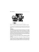
Troubleshooting
One of the primary causes of gear failure is the fact that, with few exceptions,
gear sets are designed for operation in one direction only. Failure is often
caused by inappropriate bidirectional operation of the gearbox or backward
installation of the gear set. Unless specifically manufactured for bidirectional
operation, the “nonpower” side of the gear’s teeth is not finished. Therefore,
this side is rougher and does not provide the same tolerance as the finished
“power” side.
Note that it has become standard practice in some plants to reverse the
pinion or bullgear in an effort to extend the gear set’s useful life. While this
310 Gears and Gearboxes
Table 14.1 Common failure modes of gearboxes and gear sets
THE PROBLEM
THE CAUSES
Gear failures
Variations in torsional power
Insufficient power output
Overheated bearings
Short bearing life
Overload on driver
High vibration
High noise levels
Motor trips
Bent shaft • • • •
Broken or loose bolts or setscrews • •
Damaged motor • • •
Eliptical gears • • • •
Exceeds motor’s brake horsepower
rating
• •
Excessive or too little backlash • •
Excessive torsional loading • • • • • • •
Foreign object in gearbox • • • •
Gear set not suitable for
application
• • • •
Gears mounted backward on shafts • • •
Incorrect center-to-center distance
between shafts
• •
Incorrect direction of rotation • • •
Lack of or improper lubrication • • • • • • •
Misalignment of gears or gearbox • • • • • •
Overload • • • • •
Process induced misalignment • • • •
Unstable foundation • • • •
Water or chemicals in gearbox •
Worn bearing • •
Worn couplings •
Source: Integrated Systems Inc.
Gears and Gearboxes 311
practice permits longer operation times, the torsional power generated by
a reversed gear set is not as uniform and consistent as when the gears are
properly installed.
Gear overload is another leading cause of failure. In some instances, the
overload is constant, which is an indication that the gearbox is not suitable
for the application. In other cases, the overload is intermittent and only
occurs when the speed changes or when specific production demands cause
a momentary spike in the torsional load requirement of the gearbox.
Misalignment, both real and induced, is also a primary root cause of gear
failure. The only way to assure that gears are properly aligned is to “hard
blue” the gears immediately following installation. After the gears have run
for a short time, their wear pattern should be visually inspected. If the
pattern does not conform to vendor’s specifications, alignment should be
adjusted.
Poor maintenance practices are the primary source of real misalignment
problems. Proper alignment of gear sets, especially large ones, is not an
easy task. Gearbox manufacturers do not provide an easy, positive means to
assure that shafts are parallel and that the proper center-to-center distance
is maintained.
Induced misalignment is also a common problem with gear drives. Most
gearboxes are used to drive other system components, such as bridle or
process rolls. If misalignment is present in the driven members (either real
or process induced), it also will directly affect the gears. The change in
load zone caused by the misaligned driven component will induce mis-
alignment in the gear set. The effect is identical to real misalignment within
the gearbox or between the gearbox and mated (i.e., driver and driven)
components.
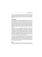
Visual inspection of gears provides a positive means to isolate the potential
root cause of gear damage or failures. The wear pattern or deformation of
gear teeth provides clues as to the most likely forcing function or cause.
The following sections discuss the clues that can be obtained from visual
inspection.
Normal Wear
Figure 14.35 illustrates a gear that has a normal wear pattern. Note that the
entire surface of each tooth is uniformly smooth above and below the pitch
line.
312 Gears and Gearboxes
Figure 14.35 Normal wear pattern
Figure 14.36 Wear pattern caused by abrasives in lubricating oil
Abnormal Wear
Figures 14.36 through 14.39 illustrate common abnormal wear patterns
found in gear sets. Each of these wear patterns suggests one or more
potential failure modes for the gearbox.
Abrasion
Abrasion creates unique wear patterns on the teeth. The pattern varies,
depending on the type of abrasion and its specific forcing function.
Figure 14.36 illustrates severe abrasive wear caused by particulates in the
lubricating oil. Note the score marks that run from the root to the tip of the
gear teeth.
Gears and Gearboxes 313
Figure 14.37 Pattern caused by corrosive attack on gear teeth
Figure 14.38 Pitting caused by gear overloading
Chemical Attack or Corrosion
Water and other foreign substances in the lubricating oil supply also cause
gear degradation and premature failure. Figure 14.37 illustrates a typical
wear pattern on gears caused by this failure mode.
Overloading
The wear patterns generated by excessive gear loading vary, but all share
similar components. Figure 14.38 illustrates pitting caused by excessive tor-
sional loading. The pits are created by the implosion of lubricating oil. Other
wear patterns, such as spalling and burning, can also help to identify specific
forcing functions or root causes of gear failure.
15 Hydraulics
“Only Permanent Repairs Made Here”
Hydraulic Knowledge
People say knowledge is power. This is true in hydraulic maintenance. Many
maintenance organizations do not know what their maintenance personnel
should know. We believe in an industrial maintenance organization where
we should divide the hydraulic skill necessary into two groups. One is
the hydraulic troubleshooter; they must be your experts in maintenance,
and this should be as a rule of thumb 10% or less of your maintenance
workforce. The other 90% plus would be your general hydraulic main-
tenance personnel. They are the personnel that provide the preventive
maintenance expertise. The percentages we give you are based on a com-
pany developing a true preventive/proactive maintenance approach to
its hydraulic systems. Let’s talk about what the hydraulic troubleshooter
knowledge and skills should be.
Hydraulic Troubleshooter
Knowledge:
●
Mechanical principles (force, work, rate, simple machines)
●
Math (basic math, complex math equations)
●
Hydraulic components (application and function of all hydraulic system
components)
●
Hydraulic schematic symbols (understanding all symbols and their rela-
tionship to a hydraulic system)
●
Calculating flow, pressure, and speed
●
Calculating the system filtration necessary to achieve the system’s proper
ISO particulate code
Hydraulics 315
Skill:
●
Trace a hydraulic circuit to 100% proficiency
●
Set the pressure on a pressure compensated pump
●
Tune the voltage on an amplifier card
●
Null a servo valve
●
Troubleshoot a hydraulic system and utilize “Root Cause Failure Analysis”
●
Replace any system component to manufacturer’s specification.
●
Develop a PM program for a hydraulic system.
●
Flush a hydraulic system after a major component failure
General Maintenance Person
Knowledge:
●
Filters (function, application, installation techniques)
●
Reservoirs (function, application)
●
Basic hydraulic system operation
●
Cleaning of hydraulic systems
●
Hydraulic lubrication principles
●
Proper PM techniques for hydraulics
Skill:
●
Change a hydraulic filter and other system components
●
Clean a hydraulic reservoir
●
Perform PM on a hydraulic system
●
Change a strainer on a hydraulic pump
●
Add filtered fluid to a hydraulic system
●
Identify potential problems on a hydraulic system
●
Change a hydraulic hose, fitting, or tubing
316 Hydraulics
Best Maintenance Hydraulic Repair Practices
In order to maintain your hydraulic systems, you must have preventive
maintenance procedures and you must have a good understanding and
knowledge of “Best Maintenance Practices” for hydraulic systems. We will
convey these practices to you. See Table 15.1.
Table 15.1 Best maintenance repair practices: hydraulics
Component
Component knowledge Best practices Frequency
Hydraulic
fluid filter
There are two types of
filters on a hydraulic
system.
Clean the filter cover
or housing with a
cleaning agent and
clean rags.
Preferred: based
on historical
trending of oil
samples.
1. Pressure filter:
Pressure filters come in
collapsible and
noncollapsible types.
The preferred filter is
the noncollapsible type.
Remove the old
filter with clean
hands and install
new filter into the
filter housing or
screw into place.
Least preferred:
Based on
equipment
manufacture’s
recommen-
dations.
2. Return filter:
Typically has a bypass,
which will allow
contaminated oil to
bypass the filter before
indicating the filter
needs to be changed.
CAUTION: NEVER
allow your hand
to touch a filter
cartridge. Open the
plastic bag and
insert the filter
without touching
the filter with your
hand.
Reservoir air
breather
The typical screen
breather should not be
used in a contaminated
environment. A filtered
air breather with a
rating of 10 micron is
preferred because of
the introduction of
contaminants to a
hydraulic system.
Remove and throw
away the filter.
Preferred: Based
on historical
trending of oil
samples.
Least preferred:
Based on
equipment
manufacturer’s
recommen-
dations.
Hydraulics 317
Table 15.1 continued
Component
Component knowledge Best practices Frequency
Hydraulic
reservoir
A reservoir is used to:
Remove contamination.
Dissipate heat from the
fluid. Store a volume of
oil.
Clean the outside of
the reservoir to
include the area
under and around
the reservoir.
Remove the oil by a
filter pump into a
clean container,
which has not had
other types of fluid
in it before.
Clean the insides of
the reservoir by
opening the
reservoir and
cleaning the
reservoir with a
lint-free rag.
Afterward, spray
clean hydraulic fluid
into the reservoir
and drain out of the
system.
If any of the
following
conditions are
met:
A hydraulic
pump fails.
If the system has
been opened for
major work.
If an oil analysis
reveals excessive
contamination.
Hydraulic
pumps
A maintenance person
needs to know the type
of pump in the system
and determine how it
operates in the system.
Example: What is the
flow and pressure of
the pump during a
given operating cycle?
This information allows
a maintenance person
to trend potential
pump failure and
troubleshoot a system
problem quickly.
Check and record
flow and pressure
during specific
operating cycles.
Review graphs of
pressure and flow.
Check for excessive
fluctuation of the
hydraulic system.
(Designate the
fluctuation
allowed.)
Pressure checks:
Preferred: daily
Least preferred:
Weekly
Flow & pressure
checks:
Preferred: two
weeks
Least preferred:
monthly
318 Hydraulics
Root Cause Failure Analysis
As in any proactive maintenance organization you must perform Root Cause
Failure Analysis in order to eliminate future component failures. Most
maintenance problems or failures will repeat themselves without someone
identifying what caused the failure and proactively eliminating it. A pre-
ferred method is to inspect and analyze all component failures. Identify the
following:
●
Component name and model number
●
Location of component at the time of failure
●
Sequence or activity the system was operating at when the failure occurred
●
What caused the failure?
●
How will the failure be prevented from happening again?
Failures are not caused by an unknown factor like “bad luck,” or “it
just happened,” or “the manufacturer made a bad part.” We have found
most failures can be analyzed and prevention taken to prevent their recur-
rence. Establishing teams to review each failure can pay off in major
ways.
Preventive Maintenance
Preventive maintenance (PM) of a hydraulic system is very basic and simple
and if followed properly can eliminate most hydraulic component failure.
Preventive maintenance is a discipline and must be followed as such in
order to obtain results. We must view PM programs as performance oriented
and not activity oriented. Many organizations have good PM procedures
but do not require maintenance personnel to follow them or hold person-
nel accountable for the proper execution of these procedures. In order to
develop a preventive maintenance program for your system you must follow
these steps:
First: Identify the system operating condition.
●
Does the system operate 24 hours a day, 7 days a week?
Hydraulics 319
●
Does the system operate at maximum flow and pressure 70% or better
during operation?
●
Is the system located in a dirty or hot environment?
Second: What requirements does the equipment manufacturer state for
preventive maintenance on the hydraulic system?
Third: What requirements and operating parameters does the component
manufacturer state concerning the hydraulic fluid ISO particulate?
Fourth: What requirements and operating parameters does the filter
company state concerning its filters’ ability to meet this requirement?
Fifth: What equipment history is available to verify the above procedures for
the hydraulic system?
As in all preventive maintenance programs, we must write procedures
required for each PM task. Steps or procedures must be written for each
task, and they must be accurate and understandable by all maintenance
personnel from entry level to master.
Preventive maintenance procedures must be a part of the PM job plan, which
includes (see Figure 15.1):
●
Tools or special equipment required for performing the task;
●
Parts or material required for performing the procedure with store room
number;
●
Safety precautions for this procedure;
●
Environmental concerns or potential hazards.
A list of preventive maintenance tasks for a hydraulic system could be:
●
Change the hydraulic filter (could be the return or pressure filter).
●
Obtain a hydraulic fluid sample.
●
Filter hydraulic fluid.
●
Check hydraulic actuators.
●
Clean the inside of a hydraulic reservoir.
●
Clean the outside of a hydraulic reservoir.
●
Check and record hydraulic pressures.
320 Hydraulics
ABC COMPANY
PREVENTIVE MAINTENANCE PROCEDURE
TASK DESCRIPTION: P.M. – Inspect hydraulic oil reserve tank level
EQUIPMENT NUMBER: 311111
FILE NUMBER: 09
FREQUENCY: 52
KEYWORD, QUALIFIER: Unit, Hydraulic (Dynamic Press)
SKILL/CRAFT: Production
PM TYPE: Inspection
SHUTDOWN REQUIRED: No
REFERENCE MANUAL/DWGS:
1. See operator manual F-378
REQUIRED TOOLS/MATERIALS:
1. Oil, Texaco Rando 68 SDK #400310
2. Flashlight
3. Oil Filter Pump
SAFETY PRECAUTIONS:
1. Observe plant and area specific safe work practices.
MAINTENANCE PROCEDURE:
1. Inspect hydraulic oil reserve tank level as follows:
a) If equipped with sight glass, verify oil level at the full mark. Add oil as required.
b) If not equipped with sight glass, remove fill plug/cap.
c) Using flashlight, verify that oil is at proper level in tank. Add oil as required.
2. Record discrepancies or unacceptable conditions in comments.
PM Procedure Courtesy of Life Cycle Engineering, Inc.
Figure 15.1 Sample preventive maintenance procedure
●
Check and record pump flow.
●
Check hydraulic hoses, tubing, and fittings.
●
Check and record voltage reading to proportional or servo valves.
●
Check and record vacuum on the suction side of the pump.
●
Check and record amperage on the main pump motor.
●
Check machine cycle time and record.
Hydraulics 321
Preventive maintenance is the core support that a hydraulic system must
have in order to maximize component life and reduce system failure.
Preventive maintenance procedures that are properly written and followed
properly will allow equipment to operate to its full potential and life cycle.
Preventive maintenance allows a maintenance department to control a
hydraulic system rather than the system controlling the maintenance depart-
ment. We must control a hydraulic system by telling it when we will perform
maintenance on it and how much money we will spend on the mainte-
nance for the system. Most companies allow hydraulic systems to control
the maintenance on them at a much higher cost.
Measuring Success
In any program we must track success in order to have support from man-
agement and maintenance personnel. We must also understand that any
action will have a reaction, negative or positive. We know successful main-
tenance programs will provide success, but we must have a checks and
balances system to ensure we are on track.
In order to measure success of a hydraulic maintenance program we must
have a way of tracking success but first we need to establish a benchmark. A
benchmark is method by which we will establish certain key measurement
tools that will tell you the current status of your hydraulic system and then
tell you if you are succeeding in your maintenance program.
Before you begin the implementation of your new hydraulic maintenance
program it would be helpful to identify and track the following information.
1 Track all downtime (in minutes) on the hydraulic system with these
questions (tracked daily):
●
What component failed?
●
Cause of failure?
●
Was the problem resolved?
●
Could this failure have been prevented?
●
Track all costs associated with the downtime (tracked daily).
●
Parts and material cost?
●
Labor cost?
322 Hydraulics
●
Production downtime cost?
●
Any other cost you may know that can be associated with a hydraulic
system failure?
2 Track hydraulic system fluid analysis. Track the following from the results
(taking samples once a month):
●
Copper content
●
Silicon content
●
H
2
O
●
Iron content
●
ISO particulate count
●
Fluid condition (viscosity, additives, and oxidation)
When the tracking process begins, you need to trend the information that
can be trended. This allows management the ability to identify trends that
can lead to positive or negative consequences. See Figure 15.2.
123456789101112
0
50
100
150
200
Particle count / PPM
Month
Monthly samples
Press Hydraulic System
Hydraulic Fluid Samples
Component
failure
Potential
component
failure
Figure 15.2 Hydraulic fluid samples
Hydraulics 323
Fluid analysis will prove the need for better filtration. The addition of a
3-micron absolute return line filter to supplement the “kidney loop” filter
can solve the problem.
Many organizations do no know where to find the method for tracking and
trending the information you need accurately. A good computerized main-
tenance management system can track and trend most of this information
for you.
Recommended Maintenance Modifications
Modifications to an existing hydraulic system need to be accomplished
professionally. A modification to a hydraulic system in order to improve
the maintenance efficiency is important to a company’s goal of maximum
equipment reliability and reduced maintenance cost.
First: Filtration pump with accessories
Objective: The objective of this pump and modification is to reduce con-
tamination that is introduced into an existing hydraulic system through the
addition of new fluid and the device used to add oil to the system.
Additional information: Hydraulic fluid from the distributor is usually not
filtered to the requirements of an operating hydraulic system. Typically, this
oil is strained to a mesh rating and not a micron rating. How clean is clean?
Typically, hydraulic fluid must be filtered to 10 microns absolute or less for
most hydraulic systems; 25 microns is the size of a white blood cell, and
40 microns is the lower limit of visibility with the unaided eye.
Many maintenance organizations add hydraulic fluid to a system through a
contaminated funnel and may even, without cleaning it, use a bucket that
has had other types of fluids and lubricants in it previously.
Recommended equipment and parts:
●
Portable filter pump with a filter rating of 3 microns absolute.
●
Quick disconnects that meet or exceed the flow rating of the portable
filter pump.
●
A
3
4
" pipe long enough to reach the bottom of the hydraulic container
your fluids are delivered in from the distributor.
324 Hydraulics
●
A 2" reducer bushing to
3
4
" NPT to fit into the 55-gallon drum, if you
receive your fluid by the drum. Otherwise, mount the filter buggy to the
double wall “tote” tank supports if you receive larger quantities.
●
Reservoir vent screens should be replaced with 3/10 micron filters, and
openings around piping entering the reservoir sealed.
Show a double wall tote tank of about 300 gallons mounted on a frame for
fork truck handling, with the pump mounted on the framework.
Also show pumping from a drum mounted on a frame for fork truck han-
dling, sitting in a catch pan, for secondary containment, with the filter buggy
attached.
Regulations require that you have secondary containment, so make every-
thing “leak” into the pan. See Figure 15.3.
Second: Modify the Hydraulic Reservoir (See Figure 15.4)
10 micron filter
55 gallon drum
Portable filter pump
To hydraulic
reservoir
Air breather
Figure 15.3 Filter pumping unit
Hydraulics 325
Drain
p
lu
g
Strainer
Baffle
plate
Mounting plate
for electric motors
and pump
Air breather
and filter
Pump
inlet
line
Drain
return
Return line
Sealed flange
Figure 15.4 Hydraulic reservoir modification
Objective: The objective is to eliminate the introduction of contamina-
tion through oil being added to the system or contaminants being added
through the air intake of the reservoir. A valve needs to be installed for oil
sampling.
Additional Information: The air breather strainer should be replaced with a
10-micron filter if the hydraulic reservoir cycles. A quick disconnect should
be installed on the bottom of the hydraulic unit and at the
3
4
level point on
the reservoir with valves to isolate the quick disconnects in case of failure.
This allows the oil to add from a filter pump as previously discussed and
would allow for external filtering of the hydraulic reservoir oil if needed.
Install a petcock valve on the front of the reservoir, which will be used for
consistent oil sampling.
Equipment and parts needed:
●
Quick disconnects that meet or exceed the flow rating of the portable
filter pump
●
Two gate valves with pipe nipples.
●
One 10-micron filter breather.
326 Hydraulics
WARNING: Do not weld on a hydraulic reservoir to install the quick
disconnects or air filter.
To summarize, maintenance of a hydraulic system is the first line of defense
to prevent component failure and thus improve equipment reliability. As
discussed earlier, discipline is the key to the success of any proactive
maintenance program.
16 Lubrication
“The Foundation of Equipment
Maintainability”
Lubrication Principles
Friction occurs when two surfaces in contact with each other attempt to
move in opposing directions at the same time. It is also defined as the
resistance to movement between two surfaces in contact with each other.
If friction happens without the benefit of a lubricant, it is called a “solid”
friction. Lubrication is defined as reducing friction to a minimum by replac-
ing solid friction with fluid friction. Reducing the friction increases the
equipment efficiency.
Kinds of Friction
Even the most carefully finished metal surface is not truly flat but is covered
with microscopic irregularities, projections, and depressions. When two dry
surfaces are rubbed together, the irregularities have a tendency to interlock
and resist the sliding motion. Under conditions of extreme pressure the
irregularities tend to weld together. Friction between moving surfaces is
grouped into three main types: sliding, rolling, and fluid.
Sliding Friction
Sliding friction occurs when two surfaces slide over each other, as in a brake
slowing down a rotating wheel on a vehicle, or a piston sliding in a cylinder.
In sliding friction, because the contact pressure is usually spread over a large
area, the pressure per square inch is relatively low.
Rolling Friction
Rolling friction takes place when a spherical or cylindrical body rolls over a
surface. Common examples of rolling friction are ball and roller bearings.
With ball or roller friction bearings the area of contact is quite small; how-
ever, the pressure loading, or pressure per square inch, is high. There is
also a very small amount of sliding friction between the ball or roller and
328 Lubrication
the separators because the components are rolling instead of sliding as in
the piston example above.
With gears, both sliding and rolling conditions exist as the gears mesh and
unmesh. They are grouped according to their contact area and action.
Fluid Friction
Fluid friction refers to air, water, or other types of fluid providing the resis-
tance to movement between two objects. One example of fluid friction
would be the resistance of air to an airplane flying. Another example would
be the torque converter in an automatic transmission; the transmission
fluid provides the power to drive the automobile through friction with the
impeller blades.
Lubrication Theory
When lubricating oil is applied to each of the component surfaces, a thin
film of oil is formed, filling up the depressions and covering the projections.
Due to the film of oil between the two surfaces, sliding, not friction, will
occur. This condition is called fluid lubrication. See Figure 16.1.
In theory, the oil forms in layers of globules, one layer adhering to each metal
surface and any number of layers of globules in between. (See Figure 16.2.)
In the illustrations, layer (1) adheres to the top surface, layer (9) in Figure
16.2(a) or layer (8) in Figure 16.2(b) adheres to the bottom surface, and
the layers in between roll over each other when the bearing surfaces move.
When these layers of oil roll over each other, the only friction present is
Figure 16.1 Magnified bearing surface with a fluid film
Lubrication 329
Figure 16.2 Globules
between the oil globules, forming what is called fluid friction. This state
of fluid friction will be maintained as long as a suitable quantity of oil is
supplied.
In plain bearings, the cohesion between the molecules of oil, plus the adhe-
sion of the oil to the metal surfaces, causes the shaft to draw oil in under it as
it revolves. This is known as “wedge action” and accounts for the presence
of the lubricating film even in heavily loaded bearings.
When the shaft is at rest, most of the film of oil between it and the bearing is
squeezed out, allowing some direct metal-to-metal contact. See Figure 16.3.
As the shaft starts to rotate, oil climbs up the bearing side in a direction
opposite to the direction of rotation. The layer of oil on the slowly turning
shaft clings to the surface and turns with it. As the oil is carried between the
shaft and the bearing it separates the bearing surfaces with a continuous
layer of oil. See Figure 16.4.
As the speed is increased, more oil is forced between the shaft and the
bearing. The shaft then has a tendency to fall to the bottom of the bearing,
but the layer of oil prevents metal-to-metal contact. See Figure 16.5.
At final speed the wedging action of the oil moves in the direction of rotation
and becomes strong enough to lift the shaft into the location.
330 Lubrication
Bearing center
Shaft center
Loaded area
Figure 16.3 Journal at rest
Bearing center
Shaft center
Oil delivery
Figure 16.4 Rolling action
The turning shaft has been likened to a pump forcing oil between shaft and
bearing, with hydraulic pressure creating an oil wedge to force the shaft
against the opposite side.
It should be noted that this theory depends on a satisfactory supply of oil
to form a continuous film. Lack of oil after the rotation begins means that a
lubricating film and wedge cannot be established, and the metal-to-metal
Lubrication 331
Bearing center
Shaft center
Oil delivery
Figure 16.5 Establishment of fluid film
contact will be maintained, generating heat and eventually wearing out the
bearing.
In Figure 16.6, the area marked C is the point of high pressure, and
the oil film is thinnest in that area. Oil should come in from the top of
low-pressure area, where it can be picked up by the shaft, and brought
around to the high-pressure area.
When rotation starts, the coefficient of friction is quite high, but as soon as
the shaft has made about half a turn, or enough to form a film of oil with
the bearing, the coefficient of friction drops to a low level.
In an antifriction bearing there are two oil wedge formations due to the
three-unit construction of the bearing.
Ball Bearing Oil Wedge Formation
●
Outer race
●
Ball
●
Inner race
Operating Conditions
Viscosity is the most important property of lubrication oil (source:
Petroleum Handbook). Viscosity is a measure of a fluid’s resistance to flow,
332 Lubrication
and it largely determines the suitability of an oil for any particular applica-
tion. The best oil for a bearing is one with the right viscosity to maintain the
“oil wedge” action efficiently, subject to conditions of speed, pressure, and
heat.
Oils with low viscosity rating are quite thin or light; while oils with high
viscosity rating flow very slowly.
The speed of a shaft and the clearance between shaft and bearing will deter-
mine the choice of oil. A slow-turning shaft with relatively wide clearance can
use heavy or high-viscosity oil, while high-speed shafts with close tolerance
bearings require a light or low viscosity oil.
Bearing load must be considered, as the oil must have enough body to main-
tain a good oil film under estimated maximum load. An oil that maintains
a film under 300 lbs. load will not stand up under a 1,000-lb. load in the
same bearing. Generally, a heavy load demands a heavier grade of oil than
does a light load, bearing areas being equal.
Pressure in the oil film builds up from zero on the incoming side to a peak
slightly past the centerline of the bearing, then drops to zero. The oil film
pressure is directly proportional to the load onthe bearing. Increase the load
and the pressure increases; decrease the load and the pressure decreases.
Regardless of the load, the pressure adjusts to provide sufficient pressure
to carry the load. Speed does not have any effect on film pressure.
Oils become thinner when heated and thicker when cooled so that temper-
ature will be a factor in determining viscosity. Heat should be considered in
two ways: heat from operation, and heat or lack of heat from surroundings.
Heat from operation is usually in a very small range, but in some machines
an allowable rise of 100
◦
F is predicted. Heat from surroundings will vary,
from an exposed bearing in winter to a bearing next to a large boiler. The
temperature range could be as much as 150
◦
F.
Properties of Oil
Viscosity
A lubricant for any machine must meet the requirements set by critical
load, speed, and temperature. The correct lubricating oil is selected for
Lubrication 333
its physical properties of viscosity and pour point, plus the extra qualities
obtained by additives or special agents. Lubricating oil is used to minimize
wear, heat rise, and power loss due to friction, to act as a cushion to absorb
shock and vibration, and to act as a cleansing agent by washing away minute
wear particles.
Viscosity ratings are obtained by a viscometer that measures the amount
of time it takes for a measured amount of oil to flow through a measured
opening at a definite temperature. (Saybolt Universal Viscosity [SUS] is the
time in seconds for 60 cubic centimeters of a fluid to flow through the
orifice of the Standard Saybolt Viscometer at a given temperature under
specified conditions.) Temperatures taken are 100
◦
F and 210
◦
F (100
◦
, 130
◦
,
210
◦
F—Shell Oil). For example, one sample of oil will take 60 seconds to
flow through the opening, while another sample of oil of the same volume
takes 600 seconds. The oil taking 60 seconds has a low viscosity rating and
is called thin oil, while the oil taking 600 seconds has a high viscosity rating
and is called heavier oil. The rate of flow of oil through the test hole will vary
with the temperature, and the viscosity readings for the different tempera-
tures give an index to the oil’s ability to withstand temperature changes.
This is called a Viscosity Index or V.I. A high V.I. means that the oil does
not change viscosity through the temperature range as much as oil with a
lower V.I.
Table 16.1 is for oils to lubricate journal bearings.
Note that for any speed, viscosity ratings increase with the heat, but that at
any heat above freezing, viscosity decreases with the speed. Pour point of
any oil is the lowest temperature at which the lubricant will flow. This is an
important characteristic when selecting an oil to be used at below-freezing
temperatures. A machine installed in a heated building will take one grade
of oil all year, but he same machine exposed to weather conditions will take
one grade of oil in the summer and a lighter grade in the winter. Any new
Table 16.1 Oil to lubricate journals—in SUS ratings
Surface speed ft./min. Below 32
◦
32
◦
–150
◦
150
◦
–200
◦
Below 150 42 65 150
150–300 42 65 120
300–750 42 50 65
Over 750 42 50 55