Machinery Components Maintenance And Repair Episode 1 Part 12 docx
Bạn đang xem bản rút gọn của tài liệu. Xem và tải ngay bản đầy đủ của tài liệu tại đây (296.36 KB, 25 trang )
Balancing of Machinery Components
265
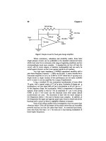
Figure 6-4. Couple unbalance.
Figure 6-4A. Discs of Figure 6-3C, realigned to cancel static unbalance, now have couple
unbalance.
Figure 6-4B. Couple unbalance in outboard rotor component.
266
Machinery Component Maintenance and Repair
couple does not matter as long as its value is equal in magnitude but opposite in direction to the unbalance couple.
Quasi-Static Unbalance
Quasi-static unbalance, Figure 6-5, is that condition of unbalance for
which the central principal axis of inertia intersects the shaft axis at a point
other than the center of gravity. It represents the specific combination of
static and couple unbalance where the angular position of one couple
component coincides with the angular position of the static unbalance.
This is a special case of dynamic unbalance.
Dynamic Unbalance
Dynamic unbalance, Figure 6-6, is that condition in which the central
principal axis of inertia is neither parallel to, nor intersects the shaft axis.
Figure 6-5. Quasi-static unbalance.
Figure 6-5A. Couple plus static unbalance results in quasi-static unbalance provided one
couple mass has the same angular position as the static mass.
Balancing of Machinery Components
267
Figure 6-5B. Unbalance in coupling causes quasi-static unbalance in rotor assembly.
Figure 6-6. Dynamic unbalance.
It is the most frequently occurring type of unbalance and can only be corrected (as is the case with couple unbalance) by mass correction in at least
two planes perpendicular to the shaft axis.
Another example of dynamic unbalance is shown in Figure 6-6A.
Motions of Unbalanced Rotors
In Figure 6-7, a rotor is shown spinning freely in space. This corresponds to spinning above resonance in soft bearings. In Figure 6-7A only
static unbalance is present and the center line of the shaft sweeps out a
cylindrical surface. Figure 6-7B illustrates the motion when only couple
unbalance is present. In this case, the centerline of the rotor shaft sweeps
out two cones which have their apexes at the center-of-gravity of the rotor.
The effect of combining these two types of unbalance when they occur in
the same axial plane (quasi-static unbalance) is to move the apex of the
cones away from the center-of-gravity. In the case of dynamic unbalance
268
Machinery Component Maintenance and Repair
Figure 6-6A. Couple unbalance plus static unbalance results in dynamic unbalance.
Figure 6-7. Effect of unbalance on free rotor motion.
there will be no apex and the shaft will move in a more complex combination of the motions shown in Figure 6-7.
Effects of Unbalance and Rotational Speed
As has been shown, an unbalanced rotor is a rotor in which the principal inertia axis does not coincide with the shaft axis.
When rotated in its bearings, an unbalanced rotor will cause periodic
vibration of, and will exert a periodic force on, the rotor bearings and
their supporting structure. If the structure is rigid, the force is larger than
if the structure is flexible (except at resonance). In practice, supporting
structures are neither entirely rigid nor entirely flexible but somewhere
in between. The rotor-bearing support offers some restraint, forming a
Balancing of Machinery Components
269
spring-mass system with damping, and having a single resonance frequency. When the rotor speed is below this frequency, the principal inertia
axis of the rotor moves outward radially. This condition is illustrated in
Figure 6-8A.
If a soft pencil is held against the rotor, the so-called high spot is marked
at the same angular position as that of the unbalance. When the rotor speed
is increased, there is a small time lag between the instant at which the
unbalance passes the pencil and the instant at which the rotor moves out
enough to contact it. This is due to the damping in the system. The angle
between these two points is called the “angle of lag” (see Figure 6-8B).
As the rotor speed is increased further, resonance of the rotor and its supporting structure will occur; at this speed the angle of lag is 90° (see Figure
6-8C). As the rotor passes through resonance, there are large vibration
amplitudes and the angle of lag changes rapidly. As the speed is increased
Figure 6-8. Angle of lag and migration of axis of rotation.
270
Machinery Component Maintenance and Repair
Figure 6-9. Angle of lag and amplitude of vibration versus rotational speed.
further, vibration subsides again; when increased to nearly twice resonance speed, the angle of lag approaches 180° (see Figure 6-8D). At
speeds greater than approximately twice resonance speed, the rotor tends
to rotate about its principal inertia axis at constant amplitude of vibration;
the angle of lag (for all practical purposes) remains 180°.
In Figure 6-8 a soft pencil is held against an unbalanced rotor. In (A)
a high spot is marked. Angle of lag between unbalance and high spot
increases from 0° (A) to 180° in (D) as rotor speed increases. The axis of
rotation has moved from the shaft axis to the principal axis of inertia.
Figure 6-9 shows the interaction of rotational speed, angle of lag, and
vibration amplitude as a rotor is accelerated through the resonance frequency of its suspension system.
Correlating CG Displacement with Unbalance
One of the most important fundamental aspects of balancing is the
direct relationship between the displacement of center-of-gravity of a rotor
from its journal axis, and the resulting unbalance. This relationship is a
prime consideration in tooling design, tolerance selection, and determination of balancing procedures.
For a disc-shaped rotor, conversion of CG displacement to unbalance,
and vice versa, is relatively simple. For longer workpieces it can be almost
as simple, if certain approximations are made. First, consider a discshaped rotor.
Assume a perfectly balanced disc, as shown in Figure 6-10, rotating
about its shaft axis and weighing 999 ounces. An unbalance mass m
of one ounce is added at a ten in. radius, bringing the total rotor weight
W up to 1,000 ounces and introducing an unbalance equivalent to
10 ounce · in. This unbalance causes the CG of the disc to be displaced
by a distance e in the direction of the unbalance mass.
Since the entire mass of the disc can be thought to be concentrated in
its center-of-gravity, it (the CG) now revolves at a distance e about the
Balancing of Machinery Components
271
Figure 6-10. Disc-shaped rotor with displaced center of gravity due to unbalance.
shaft axis, constituting an unbalance of U = We. Substituting into this
formula the known values for the rotor weight, we get:
10 oz ◊ in. = 1, 000 oz ◊ e
Solving for e we find
e=
10 oz ◊ in.
= 0.01 in.
1, 000 oz
In other words, we can find the displacement e by the following
formula:
e (in.) =
U (oz ◊ in.)
W (oz)
For example, if a fan is first balanced on a tightly fitting arbor, and subsequently installed on a shaft having a diameter 0.002 in. smaller than the
arbor, the total play resulting from the loose fit may be taken up in one
direction by a set screw. Thus the entire fan is displaced by one half of
the play or 0.001 in. from the axis about which it was originally balanced.
If we assume that the fan weighs 100 pounds, the resulting unbalance
will be:
U = 100 lb ◊ 16 oz lb ◊ 0.001 in. = 1.6 oz ◊ in.
272
Machinery Component Maintenance and Repair
The same balance error would result if arbor and shaft had the same
diameter, but the arbor (or the shaft) had a total indicated runout (TIR) of
0.002 in. In other words, the displacement is always only one half of the
total play or TIR.
The CG displacement e discussed above equals the shaft displacement
only if there is no influence from other sources, a case seldom encountered. Nevertheless, for balancing purposes, the theoretical shaft respectively CG displacement is used as a guiding parameter.
On rotors having a greater length than a disc, the formula e = U/W for
finding the correlation between unbalance and displacement still holds
true if the unbalance happens to be static only. However, if the unbalance
is anything other than static, a somewhat more complicated situation
arises.
Assume a balanced roll weighing 2,000 oz, as shown in Figure 6-11,
having an unbalance mass m of 1 oz near one end at a radius r of 10 in.
Under these conditions the displacement of the center-of-gravity (e) no
longer equals the displacement of the shaft axis (d) in the plane of the
bearing. Since shaft displacement at the journals is usually of primary
interest, the correct formula for finding it looks as follows (again assuming that there is no influence from bearings and suspension):
d=
mr
mrjh
+
W + m Iz - Ix
Where:
d = Displacement of principal inertia axis from shaft axis in plane of
bearing
W = Rotor weight
Figure 6-11. Roll with unbalance.
Balancing of Machinery Components
m
r
h
j
Ix
Iz
273
= Unbalance mass
= Radius of unbalance
= Distance from center-of-gravity to plane of unbalance
= Distance from center-of-gravity to bearing plane
= Moment of inertia around transverse axis
= Polar moment of inertia around journal axis
Since neither the polar nor the transverse moments of inertia are known,
this formula is impractical. Instead, a widely accepted approximation may
be used.
The approximation lies in the assumption that the unbalance is static
(see Figure 6-12). Total unbalance is thus 20 oz · in. Displacement of the
principal inertia axis from the bearing axis (and the eccentricity e of CG)
in the rotor is therefore:
e=
20 oz ◊ in.
= 0.01 in.
2, 000 oz
If the weight distribution is not equal between the two bearings but is,
say, 60 percent on the left bearing and 40 percent on the right bearing,
then the unbalance in the left plane must be divided by 60 percent of the
rotor weight to arrive at the approximate displacement in the left bearing
plane, whereas the unbalance in the right plane must be divided by 40
percent of the rotor weight.
An assumed unbalance of 10 oz · in. in the left plane (close to the
bearing) will thus cause an approximate eccentricity in the left bearing of:
e=
10 oz ◊ in.
= 0.00833 in.
2, 000 oz ◊ 0.6
Figure 6-12. Symmetric rotor with static unbalance.
Machinery Component Maintenance and Repair
274
and in the right bearing of:
e=
10 oz ◊ in.
= 0.0125 in.
2, 000 oz ◊ 0.4
Quite often the reverse calculation is of interest. In other words, the
unbalance is to be computed that results from a known displacement.
Again the assumption is made that the resulting unbalance is static.
For example, assume an armature and fan assembly weighing 2,000 lbs
and having a bearing load distribution of 70 percent at the armature (left)
end and 30 percent at the fan end (see Figure 6-13). Assume further that
the assembly has been balanced on its journals and that the rolling element
bearings added afterwards have a total indicated runout of 0.001 in.,
causing an eccentricity of the shaft axis of 1/2 of the TIR or 0.0005 in.
Question: How much unbalance does the bearing runout cause in each
side of the rotor?
Answer: In the armature end
U = 1, 400 lb ◊ 16 oz lb ◊ 0.0005 in. = 11.2 oz ◊ in.
In the fan end
U = 600 lb ◊ 16 oz lb ◊ 0.0005 in. = 4.8 oz ◊ in.
When investigating the effect of bearing runout on the balance quality
of a rotor, the unbalance resulting from the bearing runout should be added
to the residual unbalance to which the armature was originally balanced
on the journals; only then should the sum be compared with the recommended balance tolerance. If the sum exceeds the recommended toler-
Figure 6-13. Unbalance resulting from bearing runout in an asymmetric rotor.
Balancing of Machinery Components
275
ance, the armature will either have to be balanced to a smaller residual
unbalance on its journals, or the entire armature/bearing assembly will
have to be rebalanced in its bearings. The latter method is often preferable since it circumvents the bearing runout problem altogether, although
field replacement of bearings will be more problematic.
Balancing Machines
The purpose of a balancing machine is to determine by some technique
both the magnitude of unbalance and its angular position in each of one,
two, or more selected correction planes. For single-plane balancing this
can be done statically, but for two- or multi-plane balancing, it can be done
only while the rotor is spinning. Finally, all machines must be able to
resolve the unbalance readings, usually taken at the bearings, into equivalent values in each of the correction planes.
On the basis of their method of operation, balancing machines and
equipment can be grouped in three general categories:
1. Gravity balancing machines.
2. Centrifugal balancing machines.
3. Field balancing equipment.
In the first category, advantage is taken of the fact that a body free to
rotate always seeks that position in which its center-of-gravity is lowest.
Gravity balancing machines, also called nonrotating balancing machines,
include horizontal ways or knife-edges, roller stands, and vertical pendulum types (Figure 6-14). All are capable of only detecting and/or indicating static unbalance.
Figure 6-14. Static balancing devices.
276
Machinery Component Maintenance and Repair
In the second category, the amplitude and phase of motions or reaction
forces caused by once-per-revolution centrifugal forces resulting from
unbalance are sensed, measured, and displayed. The rotor is supported by
the machine and rotated around a horizontal or vertical axis, usually by
the drive motor of the machine. A centrifugal balancing machine (also
called a rotating balancing machine) is capable of measuring static unbalance (single plane machine) or static and couple unbalance (two-plane
machine). Only a two-plane rotating balancing machine can detect couple
and/or dynamic unbalance.
Field balancing equipment, the third category, provides sensing and
measuring instrumentation only; the necessary measurements for balancing a rotor are taken while the rotor runs in its own bearings and under
its own power. A programmable calculator or handheld computer may
be used to convert the vibration readings (obtained in several runs with
test masses) into magnitude and phase angle of the required correction
masses.
Gravity Balancing Machines
First, consider the simplest type of balancing—usually called “static”
balancing, since the rotor is not spinning.
In Figure 6-14A, a disc-type rotor on a shaft is shown resting on knifeedges. The mass added to the disc at its rim represents a known unbalance. In this illustration, and those which follow, the rotor is assumed to
be balanced without this added unbalance mass. In order for this balancing procedure to work effectively, the knife-edges must be level, parallel,
hard, and straight.
In operation, the heavier side of the disc will seek the lowest level—
thus indicating the angular position of the unbalance. Then, the magnitude of the unbalance usually is determined by an empirical process,
adding mass to the light side of the disc until it is in balance, i.e., until
the disc does not stop at the same angular position.
In Figure 6-14B, a set of balanced rollers or wheels is used in place of
the knife edges. Rollers have the advantage of not requiring as precise an
alignment or level as knife edges; also, rollers permit run-out readings to
be taken.
In Figure 6-14C, another type of static, or “nonrotating”, balancer is
shown. Here the disc to be balanced is supported by a flexible cable, fastened to a point on the disc which coincides with the center of the shaft
axis slightly above the transverse plane containing the center-of-gravity.
As shown in Figure 6-14C, the heavy side will tend to seek a lower
level than the light side, thereby indicating the angular position of the
Balancing of Machinery Components
277
unbalance. The disc can be balanced by adding mass to the diametrically
opposed side of the disc until it hangs level. In this case, the center-ofgravity is moved until it is directly under the flexible support cable.
Static balancing is satisfactory for rotors having relatively low service
speeds and axial lengths which are small in comparison with the rotor
diameter. A preliminary static unbalance correction may be required on
rotors having a combined unbalance so large that it is impossible in a
dynamic, soft-bearing balancing machine to bring the rotor up to its proper
balancing speed without damaging the machine. If the rotor is first balanced statically by one of the methods just outlined, it is usually possible
to decrease the initial unbalance to a level where the rotor may be brought
up to balancing speed and the residual unbalance measured. Such preliminary static correction is not required on hard-bearing balancing
machines.
Static balancing is also acceptable for narrow, high speed rotors which
are subsequently assembled to a shaft and balanced again dynamically.
This procedure is common for single stages of jet engine turbines and
compressors.
Centrifugal Balancing Machines
Two types of centrifugal balancing machines are in general use today,
soft-bearing and hard-bearing machines.
Soft-Bearing Balancing Machines
The soft-bearing balancing machine derives its name from the fact that
it supports the rotor to be balanced on bearings which are very flexibly
suspended, permitting the rotor to vibrate freely in at least one direction,
usually the horizontal, perpendicular to the rotor shaft axis (see Figure 1615). Resonance of rotor and bearing system occurs at one half or less of
the lowest balancing speed so that, by the time balancing speed is reached,
the angle of lag and the vibration amplitude have stabilized and can be
measured with reasonable certainty (see Figure 6-16A).
Bearings (and the directly attached support components) vibrate in
unison with the rotor, thus adding to its mass. Restriction of vertical
motion does not affect the amplitude of vibration in the horizontal
plane, but the added mass of the bearings does. The greater the combined
rotor-and-bearing mass, the smaller will be the displacement of the bearings, and the smaller will be the output of the devices which sense the
unbalance.
278
Machinery Component Maintenance and Repair
Figure 6-15. Motion of unbalanced rotor and bearings in flexible-bearing, centrifugal balancing machines.
As far as the relationship between unbalance and bearing motion is concerned, the soft-bearing machine is faced with the same complexity as
shown in Figure 6-11.
Therefore, a direct indication of unbalance can be obtained only after
calibrating the indicating elements for a given rotor by use of test masses
which constitute a known amount of unbalance.
For this purpose the soft-bearing balancing machine instrumentation
contains the necessary circuitry and controls so that, upon proper calibration for the particular rotor to be balanced, an exact indication of
amount-of-unbalance and its angular position is obtained. Calibration
varies between parts of different mass and configuration, since displacement of the principal axis of inertia in the balancing machine bearings is
dependent upon rotor mass, bearing and suspension mass, rotor moments
of inertia, and the distance between bearings.
Balancing of Machinery Components
279
Figure 6-16. Phase angle and displacement amplitude versus rotational speed in softbearing and hard-bearing balancing machines.
Hard-Bearing Balancing Machines
Hard-bearing balancing machines are essentially of the same construction as soft-bearing balancing machines, except that their bearing supports
are significantly stiffer in the transverse horizontal direction. This results
in a horizontal resonance for the machine which occurs at a frequency
several orders of magnitude higher than that for a comparable soft-bearing
balancing machine. The hard-bearing balancing machine is designed to
operate at speeds well below this resonance (see Figure 6-16B) in an area
where the phase angle lag is constant and practically zero, and where the
amplitude of vibration—though small—is directly proportional to centrifugal forces produced by unbalance.
Since the force that a given amount of unbalance exerts at a given speed
is always the same, no matter whether the unbalance occurs in a small
or large, light or heavy rotor, the output from the sensing elements
attached to the balancing machine bearing supports remains proportional
to the centrifugal force resulting from unbalance in the rotor. The output
is not influenced by bearing mass, rotor mass, or inertia, so that a permanent relation between unbalance and sensing element output can be
established.
Centrifugal force from a given unbalance rises with the square of the
balancing speed. Output from the pick-ups rises proportionately with the
280
Machinery Component Maintenance and Repair
third power of the speed due to a linear increase from the rotational
frequency superimposed on a squared increase from centrifugal force.
Suitable integrator circuitry then reduces the pickup signal inversely proportional to the cube of the balancing speed increase, resulting in a constant unbalance readout. Unlike soft bearing balancing machines, the use
of calibration masses is not required to calibrate the machine for a given
rotor.
Angle of lag is shown as a function of rotational speed in Figure 6-16A
for soft-bearing balancing machines whose balancing speed ranges start
at approximately twice the resonance speed of the supports; and in Figure
6-16B for hard-bearing balancing machines. Here the resonance frequency
of the combined rotor-bearing support system is usually more than three
times greater than the maximum balancing speed.
For more information on hard-bearing and other types of balancing
machines, see articles on advantages of hard-bearing machines and on
balancing specific types of rotors. (Reprints are available through Schenck
Trebel Corporation.)
Both soft- and hard-bearing balancing machines use various types of
sensing elements at the rotor-bearing supports to convert mechanical
vibration into an electrical signal. These sensing elements are usually
velocity-type pickups, although certain hard-bearing balancing machines
use magnetostrictive or piezo-electric pickups.
Measurement of Amount and Angle of Unbalance
Three basic methods are used to obtain a reference signal by which the
phase angle of the amount-of-unbalance indication signal may be correlated with the rotor. On end-drive machines (where the rotor is driven via
a universal-joint driver or similarly flexible coupling shaft) a phase reference generator, directly coupled to the balancing machine drive spindle,
is used. On belt-drive machines (where the rotor is driven by a belt over
the rotor periphery) or on air-drive or self-drive machines, a stroboscopic
lamp flashing once per rotor revolution, or a scanning head (photoelectric
cell with light source) is employed to obtain the phase reference.
Whereas the scanning head only requires a single reference mark on
the rotor to obtain the angular position of unbalance, the stroboscopic light
necessitates attachment of an angle reference disc to the rotor, or placing
an adhesive numbered band around it. Under the once-per-revolution flash
of the strobe light the rotor appears to stand still so that an angle reading
can be taken opposite a stationary mark.
With the scanning head, an additional angle indicating circuit and
instrument must be employed. The output from the phase reference sensor
Balancing of Machinery Components
281
Figure 6-17. Block diagram of typical balancing machine instrumentations. (A) Amount of
unbalance indicated on analog meters, angle by strobe light. (B) Combined amount and
angle indication on Vector meters, simultaneously in two correction planes.
(scanning head) and the pickups at the rotor-bearing supports are processed and result in an indication representing the amount-of-unbalance
and its angular position.
In Figure 6-17 block diagrams are shown for typical balancing
instrumentations.
Figure 6-17A illustrates an indicating system which uses switching
between correction planes (i.e., a single-channel instrumentation). This is
generally employed on balancing machines with stroboscopic angle indication and belt drive. In Figure 6-17B an indicating system is shown with
two-channel instrumentation. Combined indication of amount of unbalance and its angular position is provided simultaneously for both correction planes on two vectormeters having illuminated targets projected on
the back of translucent overlay scales. Displacement of a target from the
central zero point provides a direct visual representation of the displacement of the principal inertia axis from the shaft axis. Concentric circles
on the overlay scale indicate the amount of unbalance, and radial lines
indicate its angular position.
282
Machinery Component Maintenance and Repair
Plane Separation
Consider the rotor in Figure 6-15 with only an unbalance mass on the
left end of the rotor. This mass causes not only the left bearing to vibrate
but, to a lesser degree, the right also. This influence is called correction
plane interference or, for short, “cross effect.” If a second mass is attached
in the right plane of the rotor, the direct effect of the mass in the right
plane combines with the cross effect of the mass in the left plane, resulting in a composite vibration of the right bearing. If the two unbalance
masses are at the same angular position, the cross effect of one mass has
the same angular position as the direct effect in the other rotor end plane;
thus, their direct and cross effects are additive (Figure 6-18A). If the two
unbalance masses are 180° out of phase, their direct and cross effects
are subtractive (Figure 6-18B). In a hard-bearing balancing machine the
additive or subtractive effects depend entirely on the ratios of distances
between the axial positions of the correction planes and bearings. In a soft-
Figure 6-18. Influence of cross effects in rotors with static and couple unbalance.
Balancing of Machinery Components
283
bearing machine, the relationship is more complex because the masses
and inertias of the rotor and its bearings must be taken into account.
If the two unbalance masses have an angular relationship other than 0
or 180°, the cross effect in the right bearing has a different phase angle
than the direct effect from the right mass. Addition or subtraction of these
effects is vectorial. The net bearing vibration is equal to the resultant of
the two vectors, as shown in Figure 6-19. Phase angle indicated by the
bearing vibration does not coincide with the angular position of either
unbalance mass.
The unbalance illustrated in Figure 6-19 is the most common type,
namely dynamic unbalance of unknown amount and angular position.
Interaction of direct and cross effects will cause the balancing process to be
a trial-and-error procedure. To avoid this, balancing machines incorporate
a feature called “plane separation” which eliminates cross effect.
Before the advent of electrical networks, cross effect was eliminated by
supporting the rotor in a cradle resting on a knife-edge and spring arrangement, as shown in Figure 6-20. Either the bearing-support members
of the cradle or the knife edge pivot point are movable so that one unbalance correction plane always can be brought into the plane of the knifeedge.
Thus any unbalance in this plane will not cause the cradle to vibrate,
whereas unbalance in all other planes will. The latter is measured and corrected in the other correction plane near the right end of the rotor body.
Then the rotor is turned end for end, so that the knife-edge is in the plane
of the first correction. Any vibration of the cradle is now due solely to
unbalance present in the plane that was first over the knife-edge. Corrections are applied to this plane until the cradle ceases to vibrate. The
Figure 6-19. Influence of cross effects in rotors with dynamic unbalance. (All vectors seen
from right side of rotor.)
284
Machinery Component Maintenance and Repair
Figure 6-20. Plane separation by mechanical means.
rotor is now in balance. If it is again turned end for end, there will be no
vibration.
Mechanical plane separation cradles restrict the rotor length, diameter,
and location of correction planes. They also constitute a large parasitic
mass which reduces sensitivity. Therefore, electric circuitry is used today
to accomplish the function of plane separation. In principle, part of the
output of each pickup is reversed in phase and fed against the output of
the other pickup. Proper potentiometer adjustment of the counter voltage
during calibration runs (with test masses attached to a balanced rotor)
eliminates the cross effect.
Classification of Centrifugal Balancing Machines
Centrifugal balancing machines may be categorized by the type of
unbalance a machine is capable of indicating (static or dynamic), the attitude of the journal axis of the workpiece (vertical or horizontal), or the
type of rotor-bearing-support system employed (soft- or hard-bearing). In
each category, one or more classes of machines are commercially built.
The four classes are described in Table 6-1.
Class I: Trial-and-Error Balancing Machines. Machines in this class are of
the soft-bearing type. They do not indicate unbalance directly in weight
units (such as ounces or grams in the actual correction planes) but indicate only displacement and/or velocity of vibration at the bearings. The
instrumentation does not indicate the amount of weight which must be
added or removed in each of the correction planes. Balancing with this
type of machine involves a lengthy trial-and-error procedure for each
rotor, even if it is one of an identical series. The unbalance indication
cannot be calibrated for specified correction planes because these
machines do not have the feature of plane separation. Field balancing
equipment usually falls into this class.
Balancing of Machinery Components
285
Table 6-1
Classification of Balancing Machines
Principle
employed
Unbalance
indicated
Attitude of
shaft axis
Gravity
(nonrotating)
Static
(single-plane)
Vertical
Horizontal
Centrifugal
(rotating)
Static
(single-plane)
Vertical
Horizontal
Centrifugal
(rotating)
Dynamic
(two-plane);
also suitable
for static
(single-plane)
Vertical
Horizontal
Type of machine
Pendulum
Knife-edges
Roller sets
Soft-bearing
Hard-bearing
Not commercially
available
Soft-bearing
Hard-bearing
Soft-bearing
Hard-bearing
Available
classes
Not classified
Not classified
II, III
III, IV
I, II, III
IV
A programmable calculator or small computer with field balancing programs, either contained on magnetic strips or on a special plug-in ROM,
will greatly reduce the trial-and-error procedure; however, calibration
masses and three runs are still required to obtain magnitude and phase
angle of unbalance on the first rotor. For subsequent rotors of the same
kind, readings may be obtained in a single run but must be manually
entered into the calculator and then suitably manipulated.
Class II: Calibratable Balancing Machines Requiring a Balanced Prototype.
Machines in this class are of the soft-bearing type using instrumentation
which permits plane separation and calibration for a given rotor type, if a
balanced master or prototype rotor with calibration masses is available.
However, the same trial-and-error procedure as for Class I machines is
required for the first of a series of identical rotors.
Class III: Calibratable Balancing Machines Not Requiring a Balanced
Prototype. Machines in this class are of the soft-bearing type using instru-
mentation which includes an integral electronic unbalance compensator.
Any (unbalanced) rotor may be used in place of a balanced master rotor
without the need for trial and error correction. Plane separation and calibration can be achieved in one or more runs with the help of calibration
masses.
This class also includes soft-bearing machines with electrically driven
shakers fitted to the vibratory part of their rotor supports.
286
Machinery Component Maintenance and Repair
Figure 6-21. A permanently calibrated hard-bearing balancing machine, showing five rotor
dimensions used in computing unbalance.
Machines in this
class are of the hard-bearing type. They are permanently calibrated by
the manufacturer for all rotors falling within the weight and speed range
of a given machine size. Unlike the machines in other classes, these
machines indicate unbalance in the first run without individual rotor
calibration. This is accomplished by the incorporation of an analog or
digital computer into the instrumentation associated with the machine.
The following five rotor dimensions (see Figure 6-21) are fed into the
computer: distance from left correction plane to left support (a); distance
between correction planes (b); distance from right correction plane to right
support (c); and r1 and r2, which are the radii of the correction masses in
the left and right planes. The instrumentation then indicates the magnitude and angular position of the required correction mass for each of the
two selected planes.
The compensation or “null-force” balancing machine falls into this
class also. Although no longer manufactured, it is still widely used. It balances at the natural frequency or resonance of its suspension system
including the rotor.
Class IV: Permanently Calibrated Balancing Machines.
Maintenance and Production Balancing Machines
Balancing machines may also be categorized by their application in the
following three groups:
Balancing of Machinery Components
287
1. Universal balancing machines.
2. Semi-automatic balancing machines.
3. Full automatic balancing machines with automatic transfer of
work.
Each of these is available in both the nonrotating and rotating types, the
latter for correction in either one or two planes.
Universal Balancing Machines
Universal balancing machines are adaptable for balancing a considerable variety of sizes and types of rotors. These machines commonly have
a capacity for balancing rotors whose weight varies as much as 100 to 1
from maximum to minimum. The elements of these machines are adapted
easily to new sizes and types of rotors. Amount and location of unbalance
are observed on suitable instrumentation by the machine operator as the
machine performs its measuring functions. This category of machine is
suitable for maintenance or job-shop balancing as well as for many small
and medium lot-size production applications.
Semi-Automatic Balancing Machines
Semi-automatic balancing machines are of many types. They vary from
an almost universal machine to an almost fully automatic machine. Machines in this category may perform automatically any one or all of the
following functions in sequence or simultaneously:
1. Retain the amount of unbalance indication for further reference.
2. Retain the angular location of unbalance indication for further
reference.
3. Measure amount and position of unbalance.
4. Couple the balancing-machine drive to the rotor.
5. Initiate and stop rotation.
6. Set the depth of a correction tool depending on indication of
amount of unbalance.
7. Index the rotor to a desired position depending on indication of
unbalance location.
8. Apply correction of the proper magnitude at the indicated location.
9. Inspect the residual unbalance after correction.
10. Uncouple the balancing-machine drive.
288
Machinery Component Maintenance and Repair
Thus, the most complete semi-automatic balancing machine performs
the entire balancing process and leaves only loading, unloading, and cycle
initiation to the operator. Other semi-automatic balancing machines
provide only means for retention of measurements to reduce operator
fatigue and error. The features which are economically justifiable on a
semi-automatic balancing machine may be determined only from a study
of the rotor to be balanced and the production requirements.
Fully-Automatic Balancing Machines
Fully automatic balancing machines with automatic transfer of the rotor
are also available. These machines may be either single- or multiplestation machines. In either case, the parts to be balanced are brought to
the balancing machine by conveyor, and balanced parts are taken away
from the balancing machine by conveyor. All the steps of the balancing
process and the required handling of the rotor are performed without an
operator. These machines also may include means for inspecting the residual unbalance as well as monitoring means to ensure that the balance
inspection operation is performed satisfactorily.
In single-station automatic balancing machines, all functions of the
balancing process (unbalance measurement, location, and correction) as
well as inspection of the complete process are performed sequentially in
a single station. In a multiple-station machine, the individual steps of the
balancing process may be performed concurrently at two or more stations.
Automatic transfer is provided between stations at which the amount
and location of unbalance are determined; then the correction for unbalance is applied; finally, the rotor is inspected for residual unbalance.
Such machines generally have shorter cycle times than single-station
machines.
Establishing a Purchase Specification
A performance type purchase specification for a balancing machine
should cover the following areas:
1. Description of the rotors to be balanced, including production rates,
and balance tolerances.
2. Special rotor requirements, tooling, methods of unbalance correction, other desired features.
3. Acceptance test procedures.
4. Commercial matters such as installation, training, warranty, etc.
Balancing of Machinery Components
289
Rotor Description
To determine the correct machine size and features for a given application, it is first necessary to establish a precise description of the rotors
to be balanced. To accumulate the necessary data. ISO 2953 suggests a
suitable format. Refer to Appendix 6C.
Supporting the Rotor in the Balancing Machine
Means of Journal Support
A prime consideration in a balancing machine is the means for supporting the rotor. Various alternates are available, such as twin rollers,
plain bearings, rolling element hearings (including slave bearings), Vroller bearings, nylon V-blocks, etc. (see also Appendix 6B, “Balancing
Machine Nomenclature,” and Appendix 6C.) The most frequently used
and easiest to adapt are twin rollers. A rotor should generally be supported
at its journals to assure that balancing is carried out around the same axis
on which it rotates in service.
Rotors with More than Two Journals
Rotors which are normally supported at more than two journals may be
balanced satisfactorily on only two journals provided that:
1. All journal surfaces are concentric with respect to the axis determined by the two journals used for support in the balancing machine.
2. The rotor is rigid at the balancing speed when supported on only two
bearings.
3. The rotor has equal stiffness in all radial planes when supported on
only two journals.
If the other journal surfaces are not concentric with respect to the axis
determined by the two supporting journals, the shaft should be straightened. If the rotor is not a rigid body, or if it has unequal stiffness in different radial planes (e.g., crankshafts), the rotor should be supported in a
(nonrotating) cradle at all journals during the balancing operation. This
cradle should supply the stiffness usually supplied to the rotor by the rotor
housing in which it is finally installed. The cradle should have minimum
mass when used with a soft-bearing machine to permit maximum balancing sensitivity.