Industrial Machinery Repair Part Episode 1 Part 10 docx
Bạn đang xem bản rút gọn của tài liệu. Xem và tải ngay bản đầy đủ của tài liệu tại đây (415.95 KB, 25 trang )
Conveyors 209
Configuration
Screw conveyors have a variety of configurations. Each is designed for spe-
cific applications and/or materials. Standard conveyors have a galvanized-
steel rotor, or helix, and trough. For abrasive and corrosive materials (e.g.,
wet ash), both the helix and trough may be hard-faced cast iron. For abra-
sives, the outer edge of the helix may be faced with a renewable strip of
Stellite (a cobalt alloy produced by Haynes Stellite Co.) or other similarly
hard material. Aluminum, bronze, Monel, or stainless steel also may be used
to construct the rotor and trough.
Short-Pitch Screw
The standard helix used for screw conveyors has a pitch approximately equal
to its outside diameter. The short-pitch screw is designed for applications
with inclines greater than 29 degrees.
Variable-Pitch Screw
Variable-pitch screws having the short pitch at the feed end automatically
control the flow to the conveyor and correctly proportion the load down
the screw’s length. Screws having what is referred to as a “short section,”
which has either a shorter pitch or smaller diameter, are self-loading and do
not require a feeder.
Cut-Flight
Cut-flight conveyors are used for conveying and mixing cereals, grains, and
other light material. They are similar to normal flight or screw conveyors,
and the only difference is the configuration of the paddles or screw. Notches
are cut in the flights to improve the mixing and conveying efficiency when
handling light, dry materials.
Ribbon Screw
Ribbon screws are used for wet and sticky materials, such as molasses, hot
tar, and asphalt. This type of screw prevents the materials from building
up and altering the natural frequency of the screw. A buildup can cause
resonance problems and possibly catastrophic failure of the unit.
Paddle Screw
The paddle-screw conveyor is used primarily for mixing materials like mortar
and paving mixtures. An example of a typical application is churning ashes
and water to eliminate dust.
Performance
Process parameters, such as density, viscosity, and temperature, must be
constantly maintained within the conveyor’s design operating envelope.
210 Conveyors
Table 10.4 Factor A for self-lubricating bronze bearings
Conveyor . 6 9 10 12 14 16 18 20 24
diameter, in
Factor A 54 96 114 171 255 336 414 510 690
Slight variations can affect performance and reliability. In intermittent appli-
cations, extreme care should be taken to fully evacuate the conveyor prior
to shutdown. In addition, caution must be exercised when restarting a
conveyor in case an improper shutdown was performed and material was
allowed to settle.
Power Requirements
The horsepower requirement for the conveyor-head shaft, H, for horizontal
screw conveyors can be determined from the following equation:
H = (ALN + CWLF) × 10 − 6
Where:
A = Factor for size of conveyor (see Table 10.4)
C = Material volume, ft
3
/h
F = Material factor, unitless (see Table 10.5)
L = Length of conveyor, feet
N = Conveyor rotation speed (rpm)
W = Density of material, lb/ft
3
In addition to H, the motor size depends on the drive efficiency (E) and
a unitless allowance factor (G), which is a function of H. Values for G are
found in Table 10.6. The value for E is usually 90%.
Motor hp = HG/E
Table 10.5 gives the information needed to estimate the power requirement:
percentages of helix loading for five groups of material, maximum material
density or capacity, allowable speeds for 6-inch and 20-inch diameter screws,
and the factor F.
Conveyors 211
Table 10.5 Power requirements by material group
Material Max. cross Max. density Max. rpm for Max. rpm for
group section % occupied of material, 6" diameter 20" diameter
by the material lb/ft
3
1 45 50 170 110
2 38 50 120 75
331 75 90 60
4 25 100 70 50
512
1
2
30 25
Group 1 F factor is 0.5 for light materials such as barley, beans, brewers grains
(dry), coal (pulverized), cornmeal, cottonseed meal, flaxseed, flour,
malt, oats, rice, and wheat.
Group 2 Includes fines and granular material. The values of F are: alum
(pulverized), 0.6; coal (slack or fines), 0.9; coffee beans, 0.4; sawdust,
0.7; soda ash (light), 0.7; soybeans, 0.5; fly ash, 0.4.
Group 3 Includes materials with small lumps mixed with fines. Values of F are:
alum, 1.4; ashes (dry), 4.0; borax, 0.7; brewers grains (wet), 0.6;
cottonseed, 0.9; salt, coarse or fine, 1.2; soda ash (heavy), 0.7.
Group 4 Includes semiabrasive materials, fines, granular, and small lumps.
Values of F are: acid phosphate (dry), 1.4; bauxite (dry), 1.8; cement
(dry), 1.4; clay, 2.0; fuller’s earth, 2.0; lead salts, 1.0; limestone
screenings, 2.0; sugar (raw), 1.0; white lead, 1.0; sulfur (lumpy), 0.8;
zinc oxide, 1.0.
Group 5 Includes abrasive lumpy materials, which must be kept from contact
with hanger bearings. Values of F are: wet ashes, 5.0; flue dirt, 4.0;
quartz (pulverized), 2.5; silica sand, 2.0; sewage sludge (wet and
sandy), 6.0.
Table 10.6 Allowance factor
H, hp 1 1–2 2–4 4–5 5
G 2 1.5 1.25 1.1 1.0
Volumetric Efficiency
Screw-conveyor performance is also determined by the volumetric effi-
ciency of the system. This efficiency is determined by the amount of slip
or bypass generated by the conveyor. The amount of slip in a screw
212 Conveyors
conveyor is primarily determined by three factors: product properties, screw
efficiency, and clearance between the screw and the conveyor barrel or
housing.
Product Properties
Not all materials or products have the same flow characteristics. Some have
plastic characteristics and flow easily. Others do not self-adhere and tend to
separate when pumped or mechanically conveyed. As a result, the volumet-
ric efficiency is directly affected by the properties of each product. This also
impacts screw performance.
Screw Efficiency
Each of the common screw configurations (i.e., short pitch, variable
pitch, cut flights, ribbon, and paddle) has varying volumetric efficiencies,
depending on the type of product that is conveyed. Screw designs or con-
figurations must be carefully matched to the product to be handled by the
system.
For most medium- to high-density products in a chemical plant, the variable-
pitch design normally provides the highest volumetric efficiency and lowest
required horsepower. Cut-flight conveyors are highly efficient for light, non-
adhering products, such as cereals, but are inefficient when handling heavy,
cohesive products. Ribbon conveyors are used to convey heavy liquids, such
as molasses, but are not very efficient and have a high slip ratio.
Clearance
Improper clearance is the source of many volumetric-efficiency problems.
It is important to maintain proper clearance between the outer ring, or
diameter, of the screw and the conveyor’s barrel, or housing, through-
out the operating life of the conveyor. Periodic adjustments to compensate
for wear, variations in product, and changes in temperature are essential.
While the recommended clearance varies with specific conveyor design and
the product to be conveyed, excessive clearance severely impacts conveyor
performance as well.
Installation
Installation requirements vary greatly with screw-conveyor design. The ven-
dor’s Operating and Maintenance (O&M) manuals should be consulted
and followed to ensure proper installation. However, as with practically all
mechanical equipment, there are basic installation requirements common
Conveyors 213
to all screw conveyors. Installation requirements presented here should
be evaluated in conjunction with the vendor’s O&M manual. If the infor-
mation provided here conflicts with the vendor-supplied information, the
O&M manual’s recommendations should always be followed.
Foundation
The conveyor and its support structure must be installed on a rigid foun-
dation that absorbs the torsional energy generated by the rotating screws.
Because of the total overall length of most screw conveyors, a single founda-
tion that supports the entire length and width should be used. There must
be enough lateral (i.e., width) stiffness to prevent flexing during normal
operation. Mounting conveyor systems on decking or suspended-concrete
flooring should provide adequate support.
Support Structure
Most screw conveyors are mounted above the foundation level on a support
structure that generally has a slight downward slope from the feed end to the
discharge end. While this improves the operating efficiency of the conveyor,
it also may cause premature wear of the conveyor and its components.
The support’s structural members (i.e., I-beams and channels) must be
adequately rigid to prevent conveyor flexing or distortion during normal
operation. Design, sizing, and installation of the support structure must
guarantee rigid support over the full operating range of the conveyor. When
evaluating the structural requirements, variations in product type, density,
and operating temperature must also be considered. Since these variables
directly affect the torsional energy generated by the conveyor, the worst-case
scenario should be used to design the conveyor’s support structure.
Product-Feed System
One of the major limiting factors of screw conveyors is their ability to provide
a continuous supply of incoming product. While some conveyor designs,
such as those having a variable-pitch screw, provide the ability to self-feed,
their installation should include a means of ensuring a constant, consistent
incoming supply of product.
In addition, the product-feed system must prevent entrainment of contam-
inants in the incoming product. Normally, this requires an enclosure that
seals the product from outside contaminants.
214 Conveyors
Operating Methods
As previously discussed, screw conveyors are sensitive to variations in
incoming product properties and the operating environment. Therefore,
the primary operating concern is to maintain a uniform operating envelope
at all times, in particular by controlling variations in incoming product and
operating environment.
Incoming-Product Variations
Any measurable change in the properties of the incoming product directly
affects the performance of a screw conveyor. Therefore, the operating prac-
tices should limit variations in product density, temperature, and viscosity.
If they occur, the conveyor’s speed should be adjusted to compensate for
them.
For property changes directly related to product temperature, preheaters
or coolers can be used in the incoming-feed hopper, and heating/cooling
traces can be used on the conveyor’s barrel. These systems provide a means
of achieving optimum conveyor performance despite variations in incoming
product.
Operating-Environment Variations
Changes in the ambient conditions surrounding the conveyor system
may also cause deviations in performance. A controlled environment will
substantially improve the conveyor’s efficiency and overall performance.
Therefore, operating practices should include ways to adjust conveyor
speed and output to compensate for variations. The conveyor should be
protected from wind chill, radical variations in temperature and humidity,
and any other environment-related variables.
11 Couplings
Couplings are designed to provide two functions: (1) to transmit torsional
power between a power source and driven unit and (2) to absorb torsional
variations in the drive train. They are not designed to correct misalignment
between two shafts. While certain types of couplings provide some correc-
tion for slight misalignment, reliance on these devices to obtain alignment
is not recommended.
Coupling Types
The sections to follow provide overviews of the more common coupling
types: rigid and flexible. Also discussed are couplings used for special
applications: floating-shaft (spacer) and fluid (hydraulic).
Rigid Couplings
A rigid coupling permits neither axial nor radial relative motion between
the shafts of the driver and driven unit. When the two shafts are connected
solidly and properly, they operate as a single shaft. A rigid coupling is pri-
marily used for vertical applications, e.g., vertical pumps. Types of rigid
couplings discussed in this section are flanged, split, and compression.
Flanged couplings are used where there is free access to both shafts. Split
couplings are used where access is limited on one side. Both flanged and
split couplings require the use of keys and keyways. Compression couplings
are used when it is not possible to use keys and keyways.
Flanged Couplings
A flanged rigid coupling is comprised of two halves, one located on the
end of the driver shaft and the other on the end of the driven shaft. These
halves are bolted together to form a solid connection. To positively transmit
torque, the coupling incorporates axially fitted keys and split circular key
rings or dowels, which eliminate frictional dependency for transmission.
The use of flanged couplings is restricted primarily to vertical pump shafts.
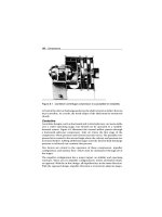
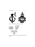
A typical flanged rigid coupling is illustrated in Figure 11.1.
216 Couplings
Figure 11.1 Typical flanged rigid coupling
Split Couplings
A split rigid coupling, also referred to as a clamp coupling, is basically a
sleeve that is split horizontally along the shaft and held together with bolts.
It is clamped over the adjoining ends of the driver and driven shafts, forming
a solid connection. Clamp couplings are used primarily on vertical pump
shafting. A typical split rigid coupling is illustrated in Figure 11.2. As with the
flanged coupling, the split rigid coupling incorporates axially fitted keys and
split circular key rings to eliminate frictional dependency in the transmission
of torque.
Compression Coupling
A rigid compression coupling is comprised of three pieces: a compressible
core and two encompassing coupling halves that apply force to the core.
The core is comprised of a slotted bushing that has been machine bored
to fit both ends of the shafts. It also has been machined with a taper on
its external diameter from the center outward to both ends. The coupling
halves are finish bored to fit this taper. When the coupling halves are bolted
together, the core is compressed down on the shaft by the two halves, and
the resulting frictional grip transmits the torque without the use of keys. A
typical compression coupling is illustrated in Figure 11.3.
Couplings 217
Figure 11.2 Typical split rigid coupling
Figure 11.3 Typical compression rigid coupling
218 Couplings
Flexible Couplings
Flexible couplings, which are classified as mechanical flexing, material flex-
ing, or combination, allow the coupled shafts to slide or move relative to
each other. Although clearances are provided to permit movement within
specified tolerance limits, flexible couplings are not designed to compensate
for major misalignments. (Shafts must be aligned to less than 0.002 inches
for proper operation.) Significant misalignment creates a whipping move-
ment of the shaft, adds thrust to the shaft and bearings, causes axial
vibrations, and leads to premature wear or failure of equipment.
Mechanical Flexing
Mechanical-flexing couplings provide a flexible connection by permitting
the coupling components to move or slide relative to each other. In order to
permit such movement, clearance must be provided within specified limits.
It is important to keep cross loading on the connected shafts at a minimum.
This is accomplished by providing adequate lubrication to reduce wear on
the coupling components. The most popular of the mechanical-flexing type
are the chain and gear couplings.
Chain
Chain couplings provide a good means of transmitting proportionately high
torque at low speeds. Minor shaft misalignment is compensated for by
means of clearances between the chain and sprocket teeth and the clearance
that exists within the chain itself.
The design consists of two hubs with sprocket teeth connected by a chain of
the single-roller, double-roller, or silent type. A typical example of a chain
coupling is illustrated in Figure 11.4.
Special-purpose components may be specified when enhanced flexibility
and reduced wear is required. Hardened sprocket teeth, special tooth
design, and barrel-shaped rollers are available for special needs. Light-
duty drives are sometimes supplied with nonmetallic chains on which no
lubrication should be used.
Gear
Gear couplings are capable of transmitting proportionately high torque at
both high and low speeds. The most common type of gear coupling consists
of two identical hubs with external gear teeth and a sleeve, or cover, with
matching internal gear teeth. Torque is transmitted through the gear teeth,
Couplings 219
Roller-chain coupling.
Coupling cover (1/2 shown)
(optional)
Roller chain
1 req’d. to
join couplers
Coupling body(s)
1 req’d. for each shaft
Figure 11.4 Typical chain coupling
whereas the necessary sliding action and ability for slight adjustments in
position comes from a certain freedom of action provided between the two
sets of teeth.
Slight shaft misalignment is compensated for by the clearance between the
matching gear teeth. However, any degree of misalignment decreases the
useful life of the coupling and may cause damage to other machine-train
components such as bearings. A typical example of a gear-tooth coupling is
illustrated in Figure 11.5.
220 Couplings
Figure 11.5 Typical gear-tooth coupling
Material-Flexing
Material-flexing couplings incorporate elements that accommodate a certain
amount of bending or flexing. The material-flexing group includes lamina-
ted disk-ring, bellows, flexible shaft, diaphragm, and elastomeric couplings.
Various materials, such as metal, plastics, or rubber, are used to make the
flexing elements in these couplings. The use of the couplings is governed by
the operational fatigue limits of these materials. Practically all metals have
fatigue limits that are predictable; therefore, they permit definite bound-
aries of operation to be established. Elastomers such as plastic or rubber,
however, usually do not have a well defined fatigue limit. Their service life
is determined primarily by conditions of installation and operation.
Laminated Disk-Ring
The laminated disk-ring coupling consists of shaft hubs connected to a single
flexible disk, or a series of disks, that allows axial movement. The laminated
disk-ring coupling also reduces heat and axial vibration that can transmit
Couplings 221
Laminated disk-ring coupling
(high speed spacer type)
Laminated disk-ring coupling
(standard double-engagement)
Morflex couplings Dropout style
Figure 11.6 Typical laminated disk-ring couplings
between the driver and driven unit. Figure 11.6 illustrates some typical
laminated disk-ring couplings.
Bellows
Bellows couplings consist of two shaft hubs connected to a flexible bel-
lows. This design, which compensates for minor misalignment, is used at
moderate rotational torque and shaft speed. This type of coupling provides
flexibility to compensate for axial movement and misalignment caused by
thermal expansion of the equipment components. Figure 11.7 illustrates a
typical bellows coupling.
Flexible Shaft or Spring
Flexible shaft or spring couplings are generally used in small equipment
applications that do not experience high torque loads. Figure 11.8 illustrates
a typical flexible shaft coupling.
222 Couplings
Figure 11.7 Typical bellows coupling
Figure 11.8 Typical flexible shaft coupling
Diaphragm
Diaphragm couplings provide torsional stiffness while allowing flexibility
in axial movement. Typical construction consists of shaft hub flanges and a
diaphragm spool, which provides the connection between the driver and
driven unit. The diaphragm spool normally consists of a center shaft fas-
tened to the inner diameter of a diaphragm on each end of the spool shaft.
The shaft hub flanges are fastened to the outer diameter of the diaphragms
to complete the mechanical connection. A typical diaphragm coupling is
illustrated in Figure 11.9.
Elastomeric
Elastomeric couplings consist of two hubs connected by an elastomeric ele-
ment. The couplings fall into two basic categories, one with the element
Couplings 223
Figure 11.9 Typical diaphragm coupling
placed in shear and the other with the element placed in compression.
The coupling compensates for minor misalignments because of the flexing
capability of the elastomer. These couplings are usually applied in light- or
medium-duty applications running at moderate speeds.
With the shear-type coupling, the elastomeric element may be clamped
or bonded in place, or fitted securely to the hubs. The compression-type
couplings may be fitted with projecting pins, bolts, or lugs to connect the
components. Polyurethane, rubber, neoprene, or cloth and fiber materials
are used in the manufacture of these elements.
Although elastomeric couplings are practically maintenance free, it is good
practice to periodically inspect the condition of the elastomer and the align-
ment of the equipment. If the element shows signs of defects or wear,
it should be replaced and the equipment realigned to the manufacturer’s
specifications. Typical elastomeric couplings are illustrated in Figure 11.10.
Combination (Metallic-Grid)
The metallic-grid coupling is an example of a combination of mechanical-
flexing and material-flexing type couplings. Typical metallic-grid couplings
are illustrated in Figure 11.11.
224 Couplings
Figure 11.10 Typical elastomeric couplings
The metallic-grid coupling is a compact unit capable of transmitting high
torque at moderate speeds. The construction of the coupling consists of two
flanged hubs, each with specially grooved slots cut axially on the outer edges
of the hub flanges. The flanges are connected by means of a serpentine-
shaped spring grid that fits into the grooved slots. The flexibility of this grid
provides torsional resilience.
Special Application Couplings
Two special application couplings are discussed in this section: (1) floating-
shaft or spacer coupling and (2) hydraulic or fluid coupling.
Couplings 225
Figure 11.11 Typical metallic-grid couplings
Floating-Shaft or Spacer Coupling
Regular flexible couplings connect the driver and driven shafts with rel-
atively close ends and are suitable for limited misalignment. However,
allowances sometimes have to be made to accommodate greater misalign-
ment or when the ends of the driver and driven shafts have to be separated
by a considerable distance.
Such is the case, for example, with end-suction pump designs in which the
power unit of the pump assembly is removed for maintenance by being
axially moved toward the driver. If neither the pump nor the driver can be
readily removed, they should be separated sufficiently to permit withdrawal
of the pump’s power unit. An easily removable flexible coupling of sufficient
length (i.e., floating-shaft or spacer coupling) is required for this type of
maintenance. Examples of couplings for this type of application are shown
in Figure 11.12.
In addition to the maintenance application described above, this coupling
(also referred to as extension or spacer sleeve coupling) is commonly used
where equipment is subject to thermal expansion and possible misalign-
ment because of high process temperatures. The purpose of this type of
coupling is to prevent harmful misalignment with minimum separation
of the driver and driven shaft ends. An example of a typical floating-shaft
coupling for this application is shown in Figure 11.13.
The floating-shaft coupling consists of two support elements connected by
a shaft. Manufacturers use various approaches in their designs for these
couplings. For example, each of the two support elements may be of the
226 Couplings
Laminated disk-ring coupling, spacer type
Gear coupling, spindle type Gear coupling, high speed spacer type
Figure 11.12 Typical floating-shaft or spacer couplings
Figure 11.13 Typical floating-shaft or spacer couplings for high-temperature
applications
Couplings 227
Figure 11.14 Typical hydraulic coupling
single-engagement type, may consist of a flexible half-coupling on one end
and a rigid half-coupling on the other end, or may be completely flexible
with some piloting or guiding supports.
Floating-shaft gear couplings usually consist of a standard coupling with a
two-piece sleeve. The sleeve halves are bolted to rigid flanges to form two
single-flex couplings. An intermediate shaft that permits the transmission of
power between widely separated drive components, in turn, connects these.
Hydraulic or Fluid
Hydraulic couplings provide a soft start with gradual acceleration and lim-
ited maximum torque for fixed operating speeds. Hydraulic couplings
are typically used in applications that undergo torsional shock from sud-
den changes in equipment loads (e.g., compressors). Figure 11.14 is an
illustration of a typical hydraulic coupling.
Coupling Selection
Periodically, worn or broken couplings must be replaced. One of the most
important steps in performing this maintenance procedure is to ensure that
the correct replacement parts are used. After having determined the cause of
failure, it is crucial to identify the correct type and size of coupling needed.
228 Couplings
Even if practically identical in appearance to the original, a part still may
not be an adequate replacement.
The manufacturer’s specification number usually provides the information
needed for part selection. If the part is not in stock, a cross-reference
guide will provide the information needed to verify ratings and to identify
a coupling that meets the same requirements as the original.
Criteria that must be considered in part selection include: equipment type,
mode of operation, and cost. Each of these criteria is discussed in the
sections to follow.
Equipment Type
Coupling selection should be application specific and, therefore, it is impor-
tant to consider the type of equipment that it connects. For example, deman-
ding applications such as variable, high-torque machine trains require
couplings that are specifically designed to absorb radical changes in speed
and torque (e.g., metallic-grid). Less demanding applications such as run-
out table rolls can generally get by with elastomeric couplings. Table 11.1
lists the coupling type commonly used in a particular application.
Mode of Operation
Coupling selection is highly dependent on the mode of operation, which
includes torsional characteristics, speed, and the operating envelope.
Torsional Characteristics
Torque requirements are a primary concern during the selection process.
In all applications in which variable or high torque is transmitted from the
driver to the driven unit, a flexible coupling rated for the maximum torque
requirement must be used. Rigid couplings are not designed to absorb
variations in torque and should not be used.
Speed
Two speed-related factors should be considered as part of the selection
process: maximum speed and speed variation.
Maximum Speed
When selecting coupling type and size, the maximum speed rating must
be considered, which can be determined from the vendor’s catalog.
Couplings 229
Table 11.1 Coupling application overview
Application Coupling selection recommendation
Limited Misalignment Compensation
Variable, high-torque machine trains
operating at moderate speeds
Metallic-grid combination couplings
Run-out table rolls Elastomeric flexible couplings
Vertical pump shafting Flanged rigid couplings, split rigid or
clamp couplings
Keys and keyways not appropriate
(e.g., brass shafts)
Rigid compression couplings
Transmission of proportionately high
torque at low speeds
Chain couplings (mechanical-flexing)
Transmission of proportionately high
torque at both high and low speeds
Gear couplings (mechanical-flexing)
Allowance for axial movement and
reduction of heat and axial vibration
Laminated disk-ring couplings
(material-flexing)
Moderate rotational torque and shaft
speed
Bellows couplings (material-flexing)
Small equipment that does not
experience high torque loads
Flexible shaft or spring couplings
(material-flexing)
Torsional stiffness while allowing
flexibility in axial movement
Diaphragm material-flexing couplings
Light- or medium-duty applications
running at moderate speeds
Elastomeric couplings (material-
flexing)
Gradual acceleration and limited
maximum torque for fixed operating
speeds (e.g., compressors)
Hydraulic or fluid couplings
Variable or high torque and/or speed
transmission
Flexible couplings rated for the
maximum torque requirement
Greater Misalignment Compensation
Maintenance requiring considerable
distance between the driver and driven
shaft ends.
Floating-shaft or spacer couplings
Misalignment results from expansion
due to high process temperatures.
Note: Rigid couplings are not designed to absorb variations in torque and speed
and should not be used in such applications. Maximum in-service coupling speed
should be at least 15% below the maximum coupling speed rating.
230 Couplings
The maximum in-service speed of a coupling should be well below (at least
15%) the maximum speed rating. The 15% margin provides a service factor
that should be sufficient to prevent coupling damage or catastrophic failure.
Speed Variation
Variation in speed equates to a corresponding variation in torque. Most
variable-speed applications require some type of flexible coupling capable
of absorbing these torsional variations.
Operating Envelope
The operating envelope defines the physical requirements, dimensions, and
type of coupling needed in a specific application. The envelope information
should include: shaft sizes, orientation of shafts, required horsepower, full
range of operating torque, speed ramp rates, and any other data that would
directly or indirectly affect the coupling.
Cost
Coupling cost should not be the deciding factor in the selection process,
although it will certainly play a part in it. Although higher performance
couplings may be more expensive, they actually may be the cost-effective
solution in a particular application. Selecting the most appropriate coupling
for an application not only extends coupling life, but also improves the
overall performance of the machine train and its reliability.
Installation
Couplings must be installed properly if they are to operate satisfactorily. This
section discusses shaft and coupling preparation, coupling installation, and
alignment.
Shaft Preparation
A careful inspection of both shaft ends must be made to ensure that no burrs,
nicks, or scratches are present that will damage the hubs. Potentially damag-
ing conditions must be corrected before coupling installation. Emery cloth
should be used to remove any burrs, scratches, or oxidation that may be
present. A light film of oil should be applied to the shafts prior to installation.
Couplings 231
Keys and keyways also should be checked for similar defects and to ensure
that the keys fit properly. Properly sized key stock must be used with all
keyways; do not use bar stock or other material.
Coupling Preparation
The coupling must be disassembled and inspected prior to installation. The
location and position of each component should be noted so that it can
be reinstalled in the correct order. When old couplings are removed for
inspection, bolts and bolt holes should be numbered so that they can be
installed in the same location when the coupling is returned to service.
Any defects, such as burrs, should be corrected before the coupling is
installed. Defects on the mating parts of the coupling can cause interference
between the bore and shaft, preventing proper operation of the coupling.
Coupling Installation
Once the inspection shows the coupling parts to be free of defects, the hubs
can be mounted on their respective shafts. If it is necessary to heat the hubs
to achieve the proper interference fit, an oil or water bath should be used.
Spot heating using a flame or torch should be avoided, as it causes distortion
and may adversely affect the hubs.
Care must be exercised during installation of a new coupling or the reassem-
bly of an existing unit. Keys and keyways should be coated with a sealing
compound that is resistant to the lubricant used in the coupling. Seals
should be inspected to ensure that they are pliable and in good condition.
They must be installed properly in the sleeve with the lip in good contact
with the hub. Sleeve flange gaskets must be whole, in good condition, clean,
and free of nicks or cracks. Lubrication plugs must be cleaned before being
installed and must fit tightly.
The specific installation procedure is dependent on the type and mounting
configuration of the coupling. However, common elements of all coupling
installations include: spacing, bolting, lubrication, and the use of matching
parts. The sections that follow discuss these installation elements.
Spacing
Spacing between the mating parts of the coupling must be within manu-
facturer’s tolerances. For example, an elastomeric coupling must have a
specific distance between the coupling faces. This distance determines the
232 Couplings
position of the rubber boot that provides transmission of power from the
driver to the driven machine component. If this distance is not exact, the
elastomer will attempt to return to its relaxed position, inducing excessive
axial movement in both shafts.
Bolting
Couplings are designed to use a specific type of bolt. Coupling bolts have
a hardened cylindrical body sized to match the assembled coupling width.
Hardened bolts are required because standard bolts do not have the tensile
strength to absorb the torsional and shearing loads in coupling applications
and may fail, resulting in coupling failure and machine-train damage.
Lubrication
Most couplings require lubrication, and care must be taken to ensure that
the proper type and quantity is used during the installation process. Inad-
equate or improper lubrication reduces coupling reliability and reduces its
useful life. In addition, improper lubrication can cause serious damage to
the machine train. For example, when a gear-type coupling is overfilled with
grease, the coupling will lock. In most cases, its locked position will increase
the vibration level and induce an abnormal loading on the bearings of both
the driver and driven unit, resulting in bearing failure.
Matching Parts
Couplings are designed for a specific range of applications, and proper per-
formance depends on the total design of the coupling system. As a result, it
is generally not a good practice to mix coupling types. Note, however, that
it is common practice in some steel industry applications to use coupling
halves from two different types of couplings. For example, a rigid cou-
pling half is sometimes mated to a flexible coupling half, creating a hybrid.
While this approach may provide short-term power transmission, it can
result in an increase in the number, frequency, and severity of machine-train
problems.
Coupling Alignment
The last step in the installation process is verifying coupling and shaft
alignment. With the exception of special application couplings such as spin-
dles and jackshafts, all couplings must be aligned within relatively close
tolerances (i.e., 0.001 to 0.002 inch).
Couplings 233
Lubrication and Maintenance
Couplings require regular lubrication and maintenance to ensure optimum
trouble-free service life. When proper maintenance is not conducted, pre-
mature coupling failure and/or damage to machine-train components such
as bearings can be expected.
Determining Cause of Failure
When a coupling failure occurs, it is important to determine the cause of
failure. Failure may result from a coupling defect, an external condition, or
workmanship during installation.
Most faults are attributed to poorly machined surfaces causing out-of-
specification tolerances, although defective material failures also occur.
Inadequate material hardness and poor strength factors contribute to many
premature failures. Other common causes are improper coupling selection,
improper installation, and/or excessive misalignment.
Lubrication Requirements
Lubrication requirements vary depending on application and coupling
type. Because rigid couplings do not require lubrication, this section dis-
cusses lubrication requirements for mechanical-flexing, material-flexing,
and combination flexible couplings only.
Mechanical-Flexing Couplings
It is important to follow the manufacturer’s instructions for lubricat-
ing mechanical-flexing couplings, which must be lubricated internally.
Lubricant seals must be in good condition and properly fitted into place.
Coupling covers contain the lubricant and prevent contaminants from enter-
ing the coupling interior. The covers are designed in two configurations,
split either horizontally or vertically. Holes are provided in the covers to
allow lubricant to be added without coupling disassembly.
Gear couplings are one type of mechanical-flexing coupling, and there are
several ways to lubricate them: grease pack, oil fill, oil collect, and contin-
uous oil flow. Either grease or oil can be used at speeds of 3,600 rpm to
6,000 rpm. Oil is normally used as the lubricant in couplings operating over
6,000 rpm. Grease and oil-lubricated units have end gaskets and seals, which