Industrial Machinery Repair Part Episode 2 Part 5 doc
Bạn đang xem bản rút gọn của tài liệu. Xem và tải ngay bản đầy đủ của tài liệu tại đây (1.08 MB, 25 trang )
334 Lubrication
machine will have lubrication recommendations for maximum temperature
range, or any oil company will recommend a lubricant to suit.
Oiliness
Oiliness, or the ability to adhere to metal and bearing surfaces, is common
to all petroleum oils. If a super degree of oiliness is required, an additive
must be added to the oil.
Flash and Fire Points
Flash and fire point are considered only when the lubricant is exposed to
high temperatures. Flash point is the temperature at which the oil gives off
fumes that can be ignited by an open flame, usually over 300
◦
F. Fire point
is when the oil itself burns and is about 50
◦
F higher than flash point. Flash
point depends on a supply of oxygen.
Carbon Deposits
Carbon deposits are formed when oils are heated to 675
◦
F and higher and
occur mainly in the lubrication of steam and internal combustion engine
cylinders.
Anticorrosives
New lubricating oils are noncorrosive to most metals used in machines, but
through continuous use the oils slowly oxidize and form acids. Some oils
contain an additive to prevent acid formation, thus extending the life of the
oil. On aging in service, reactions sometimes take place that result in the for-
mation of insoluble substances. All deposits that settle in lubricating systems
are not the fault of oil deterioration but are usually from contamination. At
high temperatures the insoluble substances may be deposited as a varnish.
Detergent or dispersing agents are added to the oil to keep the deterioration
products in a fine state so their separation as a sludge or varnish is prevented.
Additives
Extreme Pressure (EP) additives give the oils high film strength to support
extreme loads and pressures met with hypoid gears. (This oil is not rec-
ommended for use on machinery with brass washers, bearings, or sleeves
unless the EP agent is of a type that does not attack brass.)
Lubrication 335
Antifoaming additives are added to oils used in gearboxes and light oils used
to lubricate roller bearings in high-speed applications to reduce the amount
of foaming.
A circulating oil system will encounter water in the oil due to condensation
of water vapor in the system, and sometimes by water working by the oil
seals in wet locations. Oil for this type of system should have an additive to
assure quick separation of oil from the water to prevent the formation of
emulsions. This characteristic of separation is called “demulsibility.”
Grease Characteristics and Types
Grease is made by adding a metallic soap to lubricating oil, effectively thick-
ening it to the point that it turns into grease. The soap molecules in the
grease cling together and have such a strong attraction with the oil molecules
that it is very difficult to separate the soap and the oil. The soap molecules
are “polar”—that is, they carry an electric charge that causes them to be
attracted to any electric field extending out a few molecule lengths from
most metallic bearing surfaces. This electrical attraction causes the forma-
tion of a minute layer of soap molecules on the metallic surfaces, and these
soap molecules attract molecules of oil. This attraction anchors a very thin
film of grease to the bearing surface.
Grease has a peculiar characteristic called directional fluidity. When moving
in a bearing, the grease tends to “shear” into thin layers that move in the
direction of rotation. As the shearing speed increases, the grease becomes
easier to shear. This directional fluidity is encountered only in the direction
of the shearing force, and the grease does not tend to run or be squeezed out
of a bearing, even though it is acting like a liquid. Under shearing stress, the
apparent viscosity of the grease falls rapidly until it approaches the viscosity
of the oil used in its manufacture.
Classification of Grease
The penetration number, dropping point, metallic base, and the thickening
agents used are all elements that are used to grade grease.
Penetration numbers indicate the consistency of a grease and are deter-
mined by the depth a rod with a definite surface area and weight will sink
into the grease at a certain temperature during a given time. Soft grease
has a high penetration number, while hard grease has a low penetration
number. In general, the hardness of grease increases with an increase in the
amount of thickening agent NLGI (National Lubricating Grease Institute).
336 Lubrication
Standards range from Grade 0 for the softest grade—which has the con-
sistency of rendered lard at room temperature—to 6 for the stiffest, which
approaches bar soap in hardness.
Drop point or melting point is a specification requirement. A sample of
grease is heated at a given rate in a small cup with an opening in the bottom.
The drop point is the temperature at which a drop of the sample falls from
the cup. This in not an accurate way to measure the heat tolerance of grease,
as many different greases flow from a bearing at a temperature far below
their drop point.
Thickening Agents
Soap greases (calcium base grease is an example) are made by cooking a mix-
ture of a suitable fatty acid and a portion of the petroleum oil with calcium
hydroxide. When the saponification of the acid by the lime is complete,
the water content is adjusted and the remainder of the oil incorporated.
A fine mesh wire screen removes impurities and lumps before packaging
(Imperial Oil).
Calcium base greases depend on a definite water content to stabilize the
soap/oil structure. If the water is removed, the grease has a tendency to
separate. For this reason calcium soap greases are not recommended for
temperatures over 150
◦
F due to water evaporation. Calcium soaps do not
dissolve in water, and calcium base greases may be used in damp locations—
damp or wet but not submerged in water.
Sodium base greases have very little water content and are suitable for
use at higher temperatures. Soda soaps are water-soluble, and soda base
greases are not suitable in wet conditions. Soda greases have greater stabil-
ity than lime base greases and are more often used to lubricate higher speed
antifriction bearings.
Mixtures of calcium and sodium soaps give greases that will stand a higher
temperature than a straight lime base grease but are not as water resistant
as a soda base grease.
Barium and lithium base greases are water resistant and will withstand tem-
peratures of around 350
◦
F. These greases have a long life expectancy and are
suitable for bearings in hard-to-get-at places. Lithium greases are workable
at −20
◦
F.
Aluminum base greases vary from liquid grease to solid grease. A major use
is car lubrication.
Lubrication 337
Aluminum greases are both fibrous and nonfibrous. Nonfibrous grades
resemble lime greases and are used as such. Fibrous grades are quite stringy
and are often used on slow turning shafts to cushion shock loading or in
badly worn journal bearings to prolong bearing life.
Regardless of the composition of the grease, the basic shearing action is the
same in use, one layer of grease slides over another.
The above facts for grease are approximate, and maker’s trade or informa-
tion sheets should be consulted to get actual ratings for any lubricant.
Grease and Oil: A Comparison
●
Oil is easier to handle for draining, cleaning, and refilling bearings or
gear cases.
●
Oil is more suitable for wide temperature and speed variations.
●
Oil can be used in a circulating system to act as a cooling agent and to
wash away impurities.
●
Oil can be used in a gravity flow system to lubricate a number of bearings
from one location.
●
Grease will stay in a bearing with less leaking than oil, and the seals can
be quite simple.
●
With a grease gun, grease can be forced to flow in any direction, but oil
will only flow down unless a pressure pumping system is installed.
●
In operating conditions near lubrication failure, grease is better than an
oil of the same viscosity as the blended oil, due to the extra lubrication
provided by the soap.
●
Under many working conditions grease will carry a heavier load than
the oil from which it is compounded, since the soaps impart superior
lubricating ability.
●
Greases are often more versatile than oils, and fewer grades are required
for different speed and load conditions.
Other Oil Applicators
The hand oiler or squirt can is the oldest method of applying oil and is still
in use. This method leads to extremes of over- or underlubrication.
338 Lubrication
Common oilers such as the bottle, wick, or drop feed are means of adding
oil at a gradual rate to suit operating conditions. They can be used only
above the bearing as the oil flow from them is by gravity. See Figure 16.1.
●
The wick feeder oiler uses the capillary action of a strand or strands of
wool to lift the oil out of the reservoir. The flow of oil varies according to
the number of strands of wool and the height of oil in the reservoir. The
flow will continue as long as there is a supply of oil. The capillary action
of the wick tends to filter the oil, but after a time the wick will get dirty
and the flow will decrease.
●
A drip feed oiler offers a visual check and a means of controlling the flow
of oil by adjusting the needle valve. It can be shut off when the machine
is not used, avoiding a waste of oil. The oiler is filled through a small hole
in the top, requiring care to avoid spilling oil and to keep foreign material
from entering the system. Once contaminated, the needle valve is fouled
easily by a small piece of dirt or waste.
Several types of lubricators for oiling a bearing or series of bearings (or
drip oiling chains) can be made to suit local conditions. The basic style is a
tank made from a short length of pipe with a metal removable or hinged lid
covering a smaller opening for adding oil. The bottom has a
1
2
" pipe coupling
welded on to connect to the drain line. The rate of flow is controlled by a
valve and sight glass on the drain line, which can be either pipe or tubing.
Tubing is preferred, as it can easily be led around obstructions and will
withstand more vibration. See Figure 16.6.
With the increasing use of antifriction bearings this type of lubrication is
being eliminated, or else is used only for lubricating chains.
Bottle oiler Wick feed oiler Dro
p
feed oiler
Figure 16.6 Lubricators
Lubrication 339
Where oil is used over a period of time a highly stable oil with additives to
prevent acid formation, rust formation, and formation or emulsions by any
condensation in the oil reservoir is desirable.
The ring oiler is a mechanical way of oiling a slow speed shaft. The ring has
a larger ID than the OD of the shaft. It rests on the top of the shaft with
the bottom of the ring in the oil in the bottom of the housing. As the shaft
turns, friction pulls the ring around with oil clinging to its surfaces. For long
bearings, two or more rings can be used.
●
The rings are usually of one-piece metal or two pieces hinged, or can be a
flexible light ladder chain. A one-piece ring limits the bearing to two indi-
vidual shells, but a two-piece ring or chain ring allows unit construction
for the bottom bearing.
Enclosed System
A circulating system is used mainly when there are a large number of bear-
ings on one machine or machines close together, all using the same oil.
The other general application is where a bearing or bearings on a machine
are expected to run at a high temperature, and cool oil is pumped from
the reservoir over the shaft and bearing to control heat rise. The basic cir-
culating system consists of pumped oil from the reservoir, piping to each
bearing, and a drain from each bearing back to the reservoir. The refine-
ments are individual flow control to each bearing and a visual check of each
flow.
Grease Lubrication Methods
Grease used for friction bearings is usually applied by a handheld grease
gun. Greasing with a gun has the advantage of not depending on gravity for
flow conditions. The oiler can walk on the floor level and grease bearings at
any level when they are piped to a suitable location. For fixed bearings the
usual piping is
1
8
" tubing. For movable bearings or take-up bearings in hard-
to-reach places, a loop of oil-resistant pressure hose between the bearing
and the fixed tubing will allow greasing from a distance. Bearings should be
checked at close range at frequent intervals in case the grease line breaks
or works out of the bearing. When using two or more types of grease, it is
good policy to have a gun for each.
Compression grease cups are used in hazardous areas and are screwed
directly into the bearing or into a short pipe connection to the bearing.
340 Lubrication
Flow adjustment
screw
Spring compression
g
rease cup
Compression grease cup
Compression grease cup
Figure 16.7 Compression grease cups
They present a safety hazard; if the oiler has to reach near moving machin-
ery to screw down the top or take it off there is a possibility of dirt or foreign
material getting into the grease. A spring compression grease cup will give
a steady metered supply of grease for a period of time of up to four hours.
See Figure 16.7.
Oil and Grease Lubrication: Special Applications
Enclosed Gears
The proper lubrication of gears depends on several factors, the first four of
which are most important:
●
Type of gear
●
Load
●
Speed
Lubrication 341
●
Temperature
●
Methods
Worm Gears
Wheel gears and hypoid gears generate high pressure on the contact line
and greater friction. This will call for heavier oil or one with special additives.
The higher the load on a gear, the greater will be the tooth pressure. When
the pressure is too high the oil film is broken, and metal-to-metal contact
takes place. Heavier-bodied oil or one with EP additives is needed for gears
operating under high loads.
Higher speeds call for lighter lubricants, while slower speeds allow heav-
ier lubricants. With multiple reduction gear sets having two or more steps
of reduction, the oil is selected to suit the low-speed pinion on the last
reduction.
Temperature variations are influenced by the surroundings and the heat
rise of operation. During operation the heat generated by friction and by
churning of the oil will increase the temperature of the unit. Hypoid and
worm gears operate with a permissible rise of 90
◦
to 100
◦
F, while other gear
types run with an estimated permissible rise of 40
◦
to 50
◦
F. Surroundings
will present a large temperature range. If the gear set is in a heated building,
the temperature variation will be only a few degrees. If the gear set is in an
outside location, the winter temperature may be so cold that the oil will
not flow properly. When this is the case, the starting temperature must be
considered when selecting the proper oil. For units located near a source of
heat or in hot areas such as a steam plant, the final temperature will decide
the choice of oil.
Splash lubrication is the most common way of lubrication in enclosed gear
systems. In most units the larger gear picks up the oil and carries it to the
mesh point, as well as splashing oil to a trough that drains to the bearings’
worm-wheel units, with the worm on the bottom lubricated by the worm
passing oil to the wheel. The oil must be kept high enough to ensure that
the gear will pick up a sufficient quantity of oil.
Open Gears
Lubrication of open gears is by means of a grease or very heavy oil. Operating
conditions have to be considered for:
●
Temperature
342 Lubrication
●
Method of application
●
Surrounding conditions
●
Gear material
●
Choice of oil
When applied by either a brush or paddle, the lubricant must be sufficiently
fluid to flow easily. During operations, the lubricant should be heavy-bodied,
viscous, and tacky. Some oils and greases can be thinned enough for applica-
tion by heating them and applying them hot. When heating is not practical,
heavy-body diluted oils can be used. These oils are thinned with a non-
flammable solvent that evaporates after exposure to air, leaving the heavy
oil to cover the surface.
Oil can also be applied to gears by a drip cup or oil can. Very slow-moving
gears can be lubricated from a bottom pan; the grease is picked up by the
teeth of the larger gear and brought around the smaller gear or gears.
If surroundings are clean, either grease or oil can be used for good results,
but if surroundings are wet or dirty, the chosen lubricant must be capable
of providing good service to meet the equipment requirements regardless
of the environment.
With the development of gears made from synthetics such as Bakelite, Nylon,
Celoron, Micarta, and others, special lubricating methods may be needed.
The ability of a nonmetallic gear to withstand petroleum lubricants should
be identified and known before a selection is made.
Choice of Oil
When making a choice of what type of oil to use in a particular situation,
several elements must be considered. Some of those items are:
●
Viscosity must be suitable to form a lubricating film under expected
maximum working conditions.
●
Chemical stability is important as the oil is continually churned into con-
tact with the air. Low stability oil will break down to form acids and
sludge.
●
Demulsibility or water separation is necessary as water is frequently
formed from condensation inside the housing.
●
Antirust additives are needed to minimize rust formation rising from water
in the gear housing.
Lubrication 343
●
High film strength is needed to sustain the oil film between the gear teeth
under load conditions.
●
EP additives are needed for use in hypoid gear trains. Note: An EP-additive
oil should be checked with the equipment supplier, as some additives are
not recommended for use with brass.
Any new equipment should have the manufacturer’s lubrication recom-
mendations. An alternative method of obtaining recommendations is to ask
your oil supplier for assistance; they will normally recommend a suitable
lubricant.
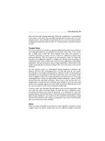
Bearings
A reduction unit with shafting in a vertical position has a pump to lubri-
cate any bearings and any gears not touching the oil in the reservoir. This
pump supplies the proper lubricant under pressure to the moving parts
throughout the equipment. See Figure 16.8.
Proper lubrication results in:
●
Reduced friction between bearing races, rolling elements, and the
separator;
●
Protection of the finished surfaces of the bearing from rust;
●
Removal or dissipation of heat;
●
Exclusion or isolation of foreign material.
Figure 16.8 Reduction unit
344 Lubrication
In many cases either oil or grease can be used, but the choice of lubricant
depends on the following conditions:
●
Operating speed;
●
Load;
●
Temperature;
●
Ease of access to bearing;
●
Cleanliness required in surrounding area.
Grease is used in the large majority of bearing applications with slow to
moderate speeds and moderate temperatures.
Grease Advantages
●
Lubrication for longer periods of time without renewal or additions
●
Requires fewer additions
●
Permits the use of simple seals as its tenacity enables it to stay in place
●
Provides a better antirust film during periods of downtime
Grease Disadvantages
●
Does not easily dissipate heat
●
Old grease is not easily removed
●
Limited to low and moderate speeds
Oil Advantages
●
Develops less fluid friction, which leads to a cooler running bearing
●
Has a flushing action on bearing surfaces to wash off dirt and abrasive
material and help dissipate heat
●
Is easily removed from a housing with a minimum of down time, and oil
can be changed while machine is running
Greases
●
Sodium-based greases for moderate speeds, dry conditions, and temper-
atures up to 200
◦
F.
●
Calcium-based greases for moderate speeds, damp or wet conditions, and
temperatures up to 150
◦
F.
Lubrication 345
●
Lithium-based greases for moderate speeds, damp or wet conditions, and
temperatures from −30 degrees to 300
◦
F.
●
Special greases for extremes of temperature and loading conditions
Grease should be selected for its consistency at the operating temperature,
when it should be fluid enough to gradually flow to the bearing. Very soft
grease will have a tendency to churn and generate heat. Instead of being
submerged in grease, the rolling elements operate in a channel and flake
off the grease as they rotate.
The spaces between the rings should be filled with grease after assembly
and the housing packed one-third full for high speeds and one-half full for
slow speeds.
Overpacking will cause churning of the grease, higher temperatures, a
reduction in the lubricating value of the grease, and a shorter life for the
seals and for the equipment.
On low-speed applications with extreme conditions of moisture and dirt, the
housing can be completely filled with grease. This will reduce the amount
of foreign material passing the grease seal. Do not completely assemble the
bearing without grease and then use a grease gun unless the housing has a
relief fitting. Pressure will blow out the grease seals.
Oil must be selected to meet the temperature extremes and must have addi-
tives to prevent corrosion, foaming, and rusting. Oil is used for high speeds
or temperatures below zero and above 200
◦
F.
The oil bath is commonly used with the oil at a level to cover the bottom
of the outer race but not higher than the center point of the lowest ball
or roller. Overoiling produces churning and a rise in temperature. In high-
speed conditions generating heat, oil can be circulated and cooled as a
separate function, drawing heat away from the bearing and shaft.
A hot bearing is caused mainly by a lubricating fault or misalignment. No
lubrication or not enough lubrication are the common causes of overheat-
ing, but dirty or wrong grades of oil are possible causes. Misalignment of
the bearing concentrates the load on small areas at the edges of the bearing.
Newly installed bearings can have too little side clearance between the shaft
and the base, or too little clearance between the cap and the shaft. When
the bearing cap is tightened down, there is severe binding between the shaft
and the bearing. Pulling the bearing to one side when tightening down the
base bolts frequently causes misalignment.
346 Lubrication
The main objective is to keep the bearing and the shaft within normal oper-
ating temperatures. Flood the bearing with the usual grade of oil to wash
out any impurities or cuttings, then lubricate with a heavier grade of oil. The
higher velocity oil will give better protection at a higher heat. Slack off cap
bolts in a split bearing, or loosen base bolts if misalignment is suspected.
If an air hose is available, direct a flow of air against the bearing and shaft,
keeping the end of the hose a short distance from the bearing. Check the
shaft for any signs of kinking or bending, as sometimes a chain will catch or
break and wrap around the sprocket, pulling in the shaft. The hot bearing
will not show until some time after the misalignment took place.
Storage
Oil drums should be stored under cover when possible. Drums exposed to
the weather are best stood up with plastic lids to keep water from leaking
past the plugs. Storage at a regular oil house at room temperature makes
the oil easier to handle and pour. Without a separate and proper location
to store the oil, a fire hazard will exist if oil is stored at random in the plant.
Small-quantity storage areas or stations in the plant, away from traffic and
pedestrian ways and in a clean area, will do for day-to-day lubricating
requirements. The storage bin or shelter should be made of metal or wood-
covered metal and troughed to catch spills. Oils should be kept in covered
containers with each grade of oil stored in a clearly marked container. Grease
drums should be kept with the lids on.
For fire protection, a CO
2
or dry chemical extinguisher is needed at each
storage area. Good housekeeping in wiping up oil spills will reduce fire and
slipping hazards.
Best Maintenance Lubrication Practices
1 When using a grease hand gun: always clean the end of the grease gun
and the grease fitting with a clean rag or towel.
2 When using a grease hand gun: always know the amount of grease
required and the frequency. Ask a vendor’s lubrication engineer to assist
in this area. Check and mark your grease gun to ensure the amount of
grease is known and can be visualized for each type of grease gun one
uses.
Lubrication 347
3 Always take oil samples when changing oil in a gearbox.
4 When installing a new gearbox, replace the oil 24 hours after installa-
tion to remove any contamination that may have been washed from the
gearbox cavity and gears.
5 Always add hydraulic fluid into a reservoir using a filter cart (see
Chapter 17).
6 Never touch a hydraulic filter with your hand during installation. By
touching the filter you will introduce contamination to the hydraulic
system.
7 Never accept leaks on any type of lubrication line or bearing. Identify
the true problem and make a permanent repair.
8 Ensure maintenance personnel performing lubrication practices score
at least a 90% on the lubrication assessment in Chapter 3.
9 ALWAYS read and follow lubrication instructions from an equipment
manufacturer. If you must change the instructions, contact the man-
ufacturer first for comments.
In conclusion, lubrication can cause up to 80% of your equipment problems
if not performed in a disciplined manner.
17 Machinery Installation
“Installed to Specification”
Introduction
Many people believe that machinery installation starts with the foundation.
This is only true where this is a used piece of equipment. With new equip-
ment, machinery installation actually starts after the selection is made and
before the contract is drawn up. There are many items that need to be
included in the contract before the new piece of machinery is even delivered.
Remember, this is the time the manufacturer is trying to court you.
When drawing up the contract, make sure that these things are included.
You may not get every point, but now is the time to try:
●
Complete list of drawings (preferably on CAD). This list should include a
complete set of components down to bearings, shaft size, etc.
●
Installation recommendations including all electrical power needs.
●
Spare parts recommendations. Be careful with this list because it is usually
only intended to get you through the warranty period. Also make sure the
list is broken down with manufacturer numbers, such as Dodge part #,
etc.
●
Extra copies of all manuals.
●
Warranty to start once equipment is put into service, not when delivered
to site.
●
A list of preventive maintenance tasks with frequencies and lubrication
requirements.
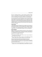
Foundation
The most important aspect of machinery installation is to provide a suitable
base or support. The capacity of this foundation must have the ability to
carry the machinery load without movement and maintaining placement.
Machinery Installation 349
Most foundations are constructed of concrete, but depending on the appli-
cation, structural steel can be used. It’s very important to look at the
condition of the cement or steel foundation. Many times you are in an older
facility where the concrete is already crumbling or the steel is rusted beyond
use. If this is the case you may have to take out the old concrete and lay a new
pad over the section or replace the structural steel. Other considerations
should be adequate space for working/running the equipment and safety.
There are many types of anchor bolts in use in industry today, such as hooked
in new concrete, compression, epoxy, etc. Make sure you check with the
manufacturer for recommendations. When hold-down bolts are subject to
extreme vibration and could possibly break at the thread section, a sleeve
can be used extending to the pocket of the foundation to form what is
commonly called a boxed anchor bolt. To allow for variations in casting
or errors in layout, a space can be left around each bolt to allow for some
change of bolt position. The use of short sections of pipe is commonly done.
The pipe should be larger in diameter than the bolt and held firmly against
the bottom of the template. Two or three times rod diameter is allowable
for the pipe. The best and most common way of locating the anchor bolts
is by the creation of a template with holes that match the mounting needs
of the machine. This does not have to be anything too elaborate and can be
made up of normal scrap parts. See Figure 17.1.
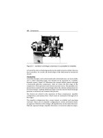
Due to the fact that over time most concrete slabs settle, whenever possi-
ble, do not mount the machinery directly to the concrete foundation. Best
practices include the use of a bed plate, which tends to be bolted to the
concrete by use of the anchor bolts. This is what the equipment is mounted
and fastened to. This provides a firm, level surface allowing for shims to be
used to accurately align the piece of equipment. By staying firmly in place
during the leveling phase, the bed plate will help machinery to stay closely
lined up. It is practical to use shims and grout. The grout will help support
all the parts and hold them in position, and the shims are used for alignment
and leveling. When constructing the foundation for grout and leveling,
3
4
"
inches to 1
1
2
" should be allowed. See Figure 17.2
Leveling and Elevation
The level is used to create a true horizontal plane. It is always a good idea
to check the accuracy of your level on a known source before starting.
350 Machinery Installation
Top of finished
foundation
Grouting
Remove waste
before pouring grout
Fill pipe with grout
Dam
Figure 17.1 Anchors
Concrete
Leave top of foundation
rough; do not finish
with trowel
Finished
grouting
Grouting 3/4 to 1½ inches
Dam
Figure 17.2 Grouting and foundations
Machinery Installation 351
Remember, level to the true plane may not be level to the continuous equip-
ment you are attaching to. The level should be used with feeler gauges to
measure the amount of drift to the true plane. The wedges of shims must
bear the weight equally to prevent the frame from distorting when the bolts
are tightened. Level on a machine is checked on two directions, both length-
wise and sideways with the use of a level on any major machine horizontal
surface. For equipment with a shaft, a shaft level will give an easy means of
checking the level in one direction. Once level has been established, tighten
down all bolts and recheck.
Elevation and line of center is just as important as level. If this piece of
machinery is used in a continuous line process, you need to have a true line
of center with the process. The best and most accurate method to use is
laser alignment. Once the piece of machinery is set into the process by the
laser, make sure to mark the equipment in its position relative to the rest
of the line at both ends. If for some reason the equipment gets moved, or
you have a problem in the process, you can easily check to see if it is still in
alignment.
Grout can be hand-mixed in buckets and is poured between the foundation
and the plate. It is extremely important to grout fully around the inside
of the bed plate. This will insure the stability of all shims and provide a
supporting surface. Installations using pipe to allow for movement of the
anchor bolt should have the pipe filled with grout for grouting under the
base. Special care must be taken with boxed anchor bolts to keep grout
from getting into the space between the bolt and the plate. Some people
will actually get fancy with the grout and build wooden frames and tuck
point edges. This is not necessary but does give a very professional look.
Before Mounting
One of the most common errors in machinery installation is not doing your
homework. It is extremely important to check with the operators of that
equipment to see how it functions and what requirements are needed. In
some cases it may be getting to the reservoir to polish the hydraulic fluid
or just having clear access underneath to keep it clean. Another point to
consider is stub-ups for hydraulics or electricity, etc. You want to make sure
that they come up in the most opportune spot to allow for easy excess,
cleaning, and operation.
352 Machinery Installation
Development of your preventive maintenance tasks is highly recommended
before mounting. This will help you to determine any special needs or
considerations to accomplish these PM tasks. There are many times that
maintenance is not considered until well after equipment is put into
operation and it is too late to make changes to the equipment.
Deciding on the type of mounts to be used is critical. In today’s modular
factory settings equipment sometimes needs to have the flexibility to be
pulled out or modified quickly. Also, certain types of equipment that require
large amounts of rebuild may need to have quick disconnecting capabilities
so they can be taken to the shop. Redundant equipment also needs this type
of flexibility.
Machinery Mounts
There are many ways of mounting machinery that are not just rigidly bolting
to the bed plate. Some equipment requires vibration dampening, automatic
leveling, or mobility. These devices need to have the capability of quick
adjustment for alignment and leveling needs. The industry standard term
for this device is “Machinery Mounts,” since we no longer require the use
of anchor bolts. In essence the machine is now freestanding. The built-in
leveling and alignment capabilities usually allow the machine to be set in
a minimum amount of time to exacting limits. Since the primary anchor is
the machine weight itself, it is important that the weight be solidly placed to
the floor. As we stated earlier, floors are very seldom level; hence the need
for the leveling devices to be built in.
Making sure to put all the recommendations of the manufacturer, opera-
tions, and maintenance engineering together is extremely important. The
key to a successful installation and start-up is the involvement of all par-
ties throughout the installation process. One other key point is to have a
start-up plan. This should include prechecks, slow ramp-up, postchecks,
and lookouts positioned at full ramp-up. Once the machine has been fully
checked out, be sure to go back and check for alignment, tightness of bolts,
and level.
18 Mixers and Agitators
Mixers are devices that blend combinations of liquids and solids into a
homogenous product. They come in a variety of sizes and configurations
designed for specific applications. Agitators provide the mechanical action
required to keep dissolved or suspended solids in solution.
Both operate on basically the same principles, but variations in design, oper-
ating speed, and applications divide the actual function of these devices.
Agitators generally work just as hard as mixers, and the terms are often
used interchangeably.
Configuration
There are two primary types of mixers: propeller/paddle and screw. Screw
mixers can be further divided into two types: batch and mixer-extruder.
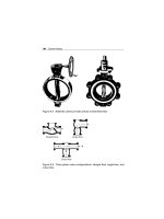
Propeller/Paddle
Propeller/paddle mixers are used to blend or agitate liquid mixtures in
tanks, pipelines, or vessels. Figure 18.1 illustrates a typical top-entering
propeller/paddle mixer. This unit consists of an electric motor, a mounting
bracket, an extended shaft, and one or more impeller(s) or propeller(s).
Materials of construction range from bronze to stainless steel and are
selected based on the particular requirements of the application.
The propeller/paddle mixer is also available in a side-entering configuration,
which is shown in Figure 18.2. This configuration is typically used to agitate
liquids in large vessels or pipelines. The side-entering mixer is essentially
the same as the top-entering version except for the mounting configuration.
Both the top-entering and side-entering mixers may use either propellers,
as shown in the preceding figures, or paddles, as illustrated by part b of
Figure 18.3. Generally, propellers are used for medium- to high-speed appli-
cations where the viscosity is relatively low. Paddles are used in low-speed,
high-viscosity applications.
354 Mixers and Agitators
Figure 18.1 Top-entering propeller-type mixer
Screw
The screw mixer uses a single- or dual-screw arrangement to mix liquids,
solids, or a combination of both. It comes in two basic configurations: batch
and combination mixer-extruder.
Batch
Figure 18.4 illustrates a typical batch-type screw mixer. This unit consists
of a mixing drum or cylinder, a single- or dual-screw mixer, and a power
supply.
The screw configuration is normally either a ribbon-type helical screw or
a series of paddles mounted on a common shaft. Materials of construction
are selected based on the specific application and materials to be mixed.
Mixers and Agitators 355
Figure 18.2 Side-entering propeller-type mixer
Typically, the screws are either steel or stainless steel, but other materials
are available.
Combination Mixer-Extruder
The mixer-extruder combination unit shown in Figure 18.5 combines the
functions of a mixer and screw conveyor. This type of mixer is used for
mixing viscous products.
Performance
Unlike for centrifugal pumps and compressors, for mixers there are few
criteria that can be used directly to determine effectiveness and efficiency.
However, product quality and brake horsepower are indices that can be
used to indirectly gauge performance.
Product Quality
The primary indicator of acceptable performance is the quality of the prod-
uct delivered by the mixer. Although there is no direct way to measure this
indicator, feedback from the quality assurance group should be used to
verify that acceptable performance levels are attained.
356 Mixers and Agitators
Figure 18.3 Mixer can use either propellers (a) or paddles (b) to provide
agitation
Figure 18.4 Batch-type mixer uses single or dual screws to mix product
Mixers and Agitators 357
Figure 18.5 Combination mixer-extruder
Brake Horsepower
Variation in the actual brake horsepower required to operate a mixer is
the primary indicator of its performance envelope. Mixer design, whether
propeller- or screw-type, is based on the viscosity of both the incoming and
finished product. These variables determine the brake horsepower required
to drive the mixer, which will follow variations in the viscosity of the prod-
ucts being mixed. As the viscosity increases, so will the brake horsepower
demand. Conversely, as the viscosity decreases, so will the horsepower
require driving the mixer.
Installation
Installation of propeller-type mixers varies greatly, depending on the
specific application. Top-entering mixers utilize either a clamp- or flange-
type mounting. It is important that the mixer be installed so the pro-
peller or paddle placement is at a point within the tank, vessel, or
piping that assures proper mixing. Vendor recommendations found in
O&M manuals should be followed to ensure proper operation of the
mixer.
Mixers should be mounted on a rigid base that assures level alignment and
prevents lateral movement of the mixer and its drive train. While most mixers
can be bolted directly to a base, care must be taken to ensure that it is rigid
and has the structural capacity to stabilize the mixer.
358 Mixers and Agitators
Operating Methods
There are only three major operating concerns for mixers: setup, incoming-
feed rate, and product viscosity.
Mixer Setup
Both propeller and screw mixers have specific setup requirements. In the
case of propeller/paddle-type mixers, the primary factor is the position of the
propellers or paddles within the tank or vessel. Vendor recommendations
should be followed to assure proper operation of the mixer.
If the propellers or paddles are too close to the liquid level, the mixer will
create a vortex that will entrain air and prevent adequate blending or mixing.
If the propellers are set too low, compress vortexing may occur. When this
happens, the mixer will create a stagnant zone in the area under the rotating
assembly. As a result, some of the product will settle in this zone, and proper
mixing cannot occur. Setting the mixer too close to a corner or the side of
the mixing vessel can also create a stagnant zone that will prevent proper
blending or mixing of the product.
For screw-type mixers, proper clearance between the rotating element and
the mixer housing must be maintained to vendor specifications. If the clear-
ance is improperly set, the mixer will bind (i.e., not enough clearance) or
fail to blend properly.
Feed Rate
Mixers are designed to handle a relatively narrow band of incoming product
flow rate. Therefore, care must be exercised to ensure that the actual feed
rate is maintained within acceptable limits. The O&M manuals provided
by the vendor will provide the feed-rate limitations for various products.
Normally, these rates must be adjusted for viscosity and temperature
variations.
Viscosity
Variations in viscosity of both the incoming and finished products have
a dramatic effect on mixer performance. Standard operating procedures
should include specific operating guidelines for the range of variation that