Industrial Machinery Repair Part Episode 1 Part 7 pps
Bạn đang xem bản rút gọn của tài liệu. Xem và tải ngay bản đầy đủ của tài liệu tại đây (475.27 KB, 25 trang )
134 Compressors
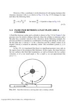
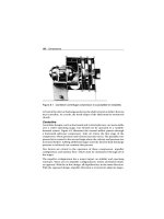
Figure 8.1 Cantilever centrifugal compressor is susceptible to instability
or load of the inlet or discharge gas forces the shaft to bend or deflect from its
true centerline. As a result, the mode shape of the shaft must be monitored
closely.
Centerline
Centerline designs, such as horizontal and vertical split-case, are more stable
over a wider operating range, but should not be operated in a variable-
demand system. Figure 8.2 illustrates the normal airflow pattern through
a horizontal split-case compressor. Inlet air enters the first stage of the
compressor, where pressure and velocity increases occur. The partially com-
pressed air is routed to the second stage where the velocity and pressure are
increased further. Adding additional stages until the desired final discharge
pressure is achieved can continue this process.
Two factors are critical to the operation of these compressors: impeller
configuration and laminar flow, which must be maintained through all of
the stages.
The impeller configuration has a major impact on stability and operating
envelope. There are two impeller configurations: in-line and back-to-back,
or opposed. With the in-line design, all impellers face in the same direction.
With the opposed design, impeller direction is reversed in adjacent stages.
Compressors 135
Figure 8.2 Airflow through a centerline centrifugal compressor
To discharge
Balancing piston
Shaft seal
Balancing line
to suction
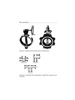
Figure 8.3 Balancing piston resists axial thrust from the in-line impeller
design of a centerline centrifugal compressor
In-Line
A compressor with all impellers facing in the same direction generates sub-
stantial axial forces. The axial pressures generated by each impeller for all
the stages are additive. As a result, massive axial loads are transmitted to the
fixed bearing. Because of this load, most of these compressors use either
a Kingsbury thrust bearing or a balancing piston to resist axial thrusting.
Figure 8.3 illustrates a typical balancing piston.
136 Compressors
All compressors that use in-line impellersmust be monitored closely for axial
thrusting. If the compressor is subjected to frequent or constant unloading,
the axial clearance will increase due to this thrusting cycle. Ultimately, this
frequent thrust loading will lead to catastrophic failure of the compressor.
Opposed
By reversing the direction of alternating impellers, the axial forces generated
by each impeller or stage can be minimized. In effect, the opposed impellers
tend to cancel the axial forces generated by the preceding stage. This
design is more stable and should not generate measurable axial thrusting.
This allows these units to contain a normal float and fixed rolling-element
bearing.
Bullgear
The bullgear design uses a direct-driven helical gear to transmit power from
the primary driver to a series of pinion-gear-driven impellers that are located
around the circumference of the bullgear. Figure 8.4 illustrates a typical
bullgear compressor layout.
First-stage
rotor
First-stage
diffuser
First-stage
intercooler
Condensate
separator
First-stage
inlet
Second-stage
inlet
Dischar
g
e
Bull gear
Fourth-stage
rotor
Fourth-stage
inlet
Third-stage
inlet
Aftercooler
Figure 8.4 Bullgear centrifugal compressor
Compressors 137
The pinion shafts are typically a cantilever-type design that has an enclosed
impeller on one end and a tilting-pad bearing on the other. The pinion
gear is between these two components. The number of impeller-pinions
(i.e., stages) varies with the application and the original equipment vendor.
However, all bullgear compressors contain multiple pinions that operate in
series.
Atmospheric air or gas enters the first-stage pinion, where the pressure
is increased by the centrifugal force created by the first-stage impeller. The
partially compressed air leaves the first stage, passes through an intercooler,
and enters the second-stage impeller. This process is repeated until the fully
compressed air leaves through the final pinion-impeller, or stage.
Most bullgear compressors are designed to operate with a gear speed of
3,600 rpm. In a typical four-stage compressor, the pinions operate at pro-
gressively higher speeds. A typical range is between 12,000 rpm (first stage)
and 70,000 rpm (fourth stage).
Because of their cantilever design and pinion rotating speeds, bullgear com-
pressors are extremely sensitive to variations in demand or downstream
pressure changes. Because of this sensitivity, their use should be limited to
baseload applications.
Bullgear compressors are not designed for, nor will they tolerate,
load-following applications. They should not be installed in the same
discharge manifold with positive-displacement compressors, especially
reciprocating compressors. The standing-wave pulses created by many
positive-displacement compressors create enough variation in the discharge
manifold to cause potentially serious instability.
In addition, the large helical gear used for the bullgear creates an axial
oscillation or thrusting that contributes to instability within the compressor.
This axial movement is transmitted throughout the machine-train.
Performance
The physical laws of thermodynamics, which define their efficiency and
system dynamics, govern compressed-air systems and compressors. This
section discusses both the first and second laws of thermodynamics, which
apply to all compressors and compressed-air systems. Also applying to
138 Compressors
these systems are the Ideal Gas Law and the concepts of pressure and
compression.
First Law of Thermodynamics
This law states that energy cannot be created or destroyed during a process,
such as compression and delivery of air or gas, although it may change from
one form of energy to another. In other words, whenever a quantity of
one kind of energy disappears, an exactly equivalent total of other kinds of
energy must be produced. This is expressed for a steady-flow open system
such as a compressor by the following relationship:
Net energy added Stored energy Stored energy of mass
to system as heat + of mass entering − leaving system = 0
and work system
Second Law of Thermodynamics
The second law of thermodynamics states that energy exists at various levels
and is available for use only if it can move from a higher to a lower level. For
example, it is impossible for any device to operate in a cycle and produce
work while exchanging heat only with bodies at a single fixed tempera-
ture. In thermodynamics a measure of the unavailability of energy has been
devised and is known as entropy. As a measure of unavailability, entropy
increases as a system loses heat, but it remains constant when there is no
gain or loss of heat as in an adiabatic process. It is defined by the following
differential equation:
dS =
dQ
T
where:
T = Temperature (Fahrenheit)
Q = Heat added (BTU)
Pressure/Volume/Temperature (PVT) Relationship
Pressure, temperature, and volume are properties of gases that are com-
pletely interrelated. Boyle’s Law and Charles’ Law may be combined into
one equation that is referred to as the Ideal Gas Law. This equation is always
true for ideal gases and is true for real gases under certain conditions.
P
1
V
1
T
1
=
P
2
V
2
T
2
Compressors 139
For air at room temperature, the error in this equation is less than 1% for
pressures as high as 400 psia. For air at one atmosphere of pressure, the
error is less than 1% for temperatures as low as −200
◦
F. These error factors
will vary for different gases.
Pressure/Compression
In a compressor, pressure is generated by pumping quantities of gas into
a tank or other pressure vessel. Progressively increasing the amount of gas
in the confined or fixed-volume space increases the pressure. The effects
of pressure exerted by a confined gas result from the force acting on the
container walls. This force is caused by the rapid and repeated bombard-
ment from the enormous number of molecules that are present in a given
quantity of gas.
Compression occurs when the space is decreased between the molecules.
Less volume means that each particle has a shorter distance to travel, thus
proportionately more collisions occur in a given span of time, resulting
in a higher pressure. Air compressors are designed to generate particular
pressures to meet specific application requirements.
Other Performance Indicators
The same performance indicators as those for centrifugal pumps or fans
govern centrifugal compressors.
Installation
Dynamic compressors seldom pose serious foundation problems. Since
moments and shaking forces are not generated during compressor oper-
ation, there are no variable loads to be supported by the foundation. A
foundation or mounting of sufficient area and mass to maintain compres-
sor level and alignment and to assure safe soil loading is all that is required.
The units may be supported on structural steel if necessary. The principles
defined for centrifugal pumps also apply to centrifugal compressors.
It is necessary to install pressure-relief valves on most dynamic compressors
to protect them due to restrictions placed on casing pressure, power input,
and to keep out of the compressor’s surge range. Always install a valve
capable of bypassing the full-load capacity of the compressor between its
discharge port and the first isolation valve.
140 Compressors
Operating Methods
The acceptable operating envelope for centrifugal compressors is very lim-
ited. Therefore, care should be taken to minimize any variation in suction
supply, backpressure caused by changes in demand, and frequency of
unloading. The operating guidelines provided in the compressor vendor’s
O&M manual should be followed to prevent abnormal operating behavior
or premature wear or failure of the system.
Centrifugal compressors are designed to be baseloaded and may exhibit
abnormal behavior or chronic reliability problems when used in a load-
following mode of operation. This is especially true of bullgear and
cantilever compressors. For example, a one-psig change in discharge pres-
sure may be enough to cause catastrophic failure of a bullgear compressor.
Variations in demand or backpressure on a cantilever design can cause the
entire rotating element and its shaft to flex. This not only affects the com-
pressor’s efficiency, but also accelerates wear and may lead to premature
shaft or rotor failure.
All compressor types have moving parts, high noise levels, high pressures,
and high-temperature cylinder and discharge-piping surfaces.
Positive Displacement
Positive-displacement compressors can be divided into two major classifica-
tions: rotary and reciprocating.
Rotary
The rotary compressor is adaptable to direct drive by the use of induction
motors or multicylinder gasoline or diesel engines. These compressors are
compact, relatively inexpensive, and require a minimum of operating atten-
tion and maintenance. They occupy a fraction of the space and weight of a
reciprocating machine having equivalent capacity.
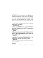
Configuration
Rotary compressors are classified into three general groups: sliding vane,
helical lobe, and liquid-seal ring.
Sliding Vane
The basic element of the sliding-vane compressor is the cylindrical housing
and the rotor assembly. This compressor, which is illustrated in Figure 8.5,
Compressors 141
Housing
Air inlet
Sliding vane
Compressed
air out
Figure 8.5 Rotary sliding-vane compressor
has longitudinal vanes that slide radially in a slotted rotor mounted eccentri-
cally in a cylinder. The centrifugal force carries the sliding vanes against the
cylindrical case with the vanes forming a number of individual longitudinal
cells in the eccentric annulus between the case and rotor. The suction port
is located where the longitudinal cells are largest. The size of each cell is
reduced by the eccentricity of the rotor as the vanes approach the discharge
port, thus compressing the gas.
Cyclical opening and closing of the inlet and discharge ports occurs by the
rotor’s vanes passing over them. The inlet port is normally a wide opening
that is designed to admit gas in the pocket between two vanes. The port
closes momentarily when the second vane of each air-containing pocket
passes over the inlet port.
When running at design pressure, the theoretical operation curves are iden-
tical (see Figure 8.6) to those of a reciprocating compressor. However, there
is one major difference between a sliding-vane and a reciprocating compres-
sor. The reciprocating unit has spring-loaded valves that open automatically
with small pressure differentials between the outside and inside cylinder.
The sliding-vane compressor has no valves.
The fundamental design considerations of a sliding-vane compressor are
the rotor assembly, cylinder housing, and the lubrication system.
Housing and Rotor Assembly
Cast iron is the standard material used to construct the cylindrical hous-
ing, but other materials may be used if corrosive conditions exist. The rotor
is usually a continuous piece of steel that includes the shaft and is made
from bar stock. Special materials can be selected for corrosive applications.
Occasionally, the rotor may be a separate iron casting keyed to a shaft. On
most standard air compressors, the rotor-shaft seals are semimetallic pack-
ing in a stuffing box. Commercial mechanical rotary seals can be supplied
142 Compressors
Design pressure
(discharge)
Operation at
design pressure
Operation abov
e
design pressure
Operation below
design pressure
PressurePressurePressure
Volume
Volume
Volume
Discharge pressure
Design pressure
Discharge pressure
Design pressure
Figure 8.6 Theoretical operation curves for rotary compressors with built-in
porting
when needed. Cylindrical roller bearings are generally used in these
assemblies.
Vanes are usually asbestos or cotton cloth impregnated with a phenolic resin.
Bronze or aluminum also may be used for vane construction. Each vane fits
into a milled slot extending the full length of the rotor and slides radially in
and out of this slot once per revolution. Vanes are the most maintenance-
prone part in the compressor. There are from 8 to 20 vanes on each rotor,
depending upon its diameter. A greater number of vanes increase compart-
mentalization, which reduces the pressure differential across each vane.
Lubrication System
A V-belt-driven, force-fed oil lubrication system is used on water-cooled com-
pressors. Oil goes to both bearings and to several points in the cylinder. Ten
times as much oil is recommended to lubricate the rotary cylinder as is
required for the cylinder of a corresponding reciprocating compressor. The
oil carried over with the gas to the line may be reduced 50% with an oil
separator on the discharge. Use of an aftercooler ahead of the separator
permits removal of 85 to 90% of the entrained oil.
Compressors 143
Figure 8.7 Helical lobe, or screw, rotary air compressor
Helical Lobe or Screw
The helical lobe, or screw, compressor is shown in Figure 8.7. It has two or
more mating sets of lobe-type rotors mounted in a common housing. The
male lobe, or rotor, is usually direct-driven by an electric motor. The female
lobe, or mating rotor, is driven by a helical gear set that is mounted on the
outboard end of the rotor shafts. The gears provide both motive power for
the female rotor and absolute timing between the rotors.
The rotor set has extremely close mating clearance (i.e., about 0.5 mils)
but no metal-to-metal contact. Most of these compressors are designed for
oil-free operation. In other words, no oil is used to lubricate or seal the
rotors. Instead, oil lubrication is limited to the timing gears and bearings that
are outside the air chamber. Because of this, maintaining proper clearance
between the two rotors is critical.
This type of compressor is classified as a constant volume, variable-
pressure machine that is quite similar to the vane-type rotary in general
characteristics. Both have a built-in compression ratio.
Helical-lobe compressors are best suited for base-load applications where
they can provide a constant volume and pressure of discharge gas. The
only recommended method of volume control is the use of variable-speed
motors. With variable-speed drives, capacity variations can be obtained with
144 Compressors
a proportionate reduction in speed. A 50% speed reduction is the maximum
permissible control range.
Helical-lobe compressors are not designed for frequent or constant cycles
between load and no-load operation. Each time the compressor unloads, the
rotors tend to thrust axially. Even though the rotors have a substantial thrust
bearing and, in some cases, a balancing piston to counteract axial thrust,
the axial clearance increases each time the compressor unloads. Over time,
this clearance will increase enough to permit a dramatic rise in the impact
energy created by axial thrust during the transient from loaded to unloaded
conditions. In extreme cases, the energy can be enough to physically push
the rotor assembly through the compressor housing.
Compression ratio and maximum inlet temperature determine the maxi-
mum discharge temperature of these compressors. Discharge temperatures
must be limited to prevent excessive distortion between the inlet and dis-
charge ends of the casing and rotor expansion. High-pressure units are
water-jacketed in order to obtain uniform casing temperature. Rotors also
may be cooled to permit a higher operating temperature.
If either casing distortion or rotor expansion occur, the clearance between
the rotating parts will decrease, and metal-to-metal contact will occur. Since
the rotors typically rotate at speeds between 3,600 and 10,000 rpm, metal-
to-metal contact normally results in instantaneous, catastrophic compressor
failure.
Changes in differential pressures can be caused by variations in either inlet
or discharge conditions (i.e., temperature, volume, or pressure). Such
changes can cause the rotors to become unstable and change the load zones
in the shaft-support bearings. The result is premature wear and/or failure
of the bearings.
Always install a relief valve that is capable of bypassing the full-load capacity
of the compressor between its discharge port and the first isolation valve.
Since helical-lobe compressors are less tolerant to over-pressure operation,
safety valves are usually set within 10% of absolute discharge pressure, or
5 psi, whichever is lower.
Liquid-Seal Ring
The liquid-ring, or liquid-piston, compressor is shown in Figure 8.8. It has a
rotor with multiple forward-turned blades that rotate about a central cone
that contains inlet and discharge ports. Liquid is trapped between adjacent
Compressors 145
Inlet port
Inlet port
Discharge por
t
Rotation
Discharge port
Inlet
Discharge
Figure 8.8 Liquid-seal ring rotary air compressor
blades, which drive the liquid around the inside of an elliptical casing. As
the rotor turns, the liquid face moves in and out of this space due to the
casing shape, creating a liquid piston. Porting in the central cone is built-in
and fixed, and there are no valves.
Compression occurs within the pockets or chambers between the blades
before the discharge port is uncovered. Since the port location must be
designed and built for a specific compression ratio, it tends to operate above
or below the design pressure (refer back to Figure 8.6).
Liquid-ring compressors are cooled directly rather than by jacketed casing
walls. The cooling liquid is fed into the casing where it comes into direct
contact with the gas being compressed. The excess liquid is discharged with
the gas. The discharged mixture is passed through a conventional baffle or
centrifugal-type separator to remove the free liquid. Because of the intimate
contact of gas and liquid, the final discharge temperature can be held close to
the inlet cooling water temperature. However, the discharge gas is saturated
with liquid at the discharge temperature of the liquid.
The amount of liquid passed through the compressor is not critical and can
be varied to obtain the desired results. The unit will not be damaged if a
large quantity of liquid inadvertently enters its suction port.
Lubrication is required only in the bearings, which are generally located
external to the casing. The liquid itself acts as a lubricant, sealing medium,
and coolant for the stuffing boxes.
146 Compressors
Performance
Performance of a rotary positive-displacement compressor can be evaluated
using the same criteria as a positive-displacement pump. As in constant-
volume machines, performance is determined by rotation speed, internal
slip, and total backpressure on the compressor.
The volumetric output of rotary positive-displacement compressors can be
controlled by speed changes. The more slowly the compressor turns, the
lower its output volume. This feature permits the use of these compressors
in load-following applications. However, care must be taken to prevent
sudden, radical changes in speed.
Internal slip is simply the amount of gas that can flow through internal
clearances from the discharge back to the inlet. Obviously, internal wear
will increase internal slip.
Discharge pressure is relatively constant regardless of operating speed. With
the exceptions of slight pressure variations caused by atmospheric changes
and backpressure, a rotary positive-displacement compressor will provide
a fixed discharge pressure. Backpressure, which is caused by restrictions in
the discharge piping or demand from users of the compressed air or gas,
can have a serious impact on compressor performance.
If backpressure is too low or demand too high, the compressor will be
unable to provide sufficient volume or pressure to the downstream sys-
tems. In this instance, the discharge pressure will be noticeably lower than
designed.
If the backpressure is too high or demand too low, the compressor will
generate a discharge pressure higher than designed. It will continue to
compress the air or gas until it reaches the unload setting on the system’s
relief valve or until the brake horsepower required exceeds the maximum
horsepower rating of the driver.
Installation
Installation requirements for rotary positive-displacement compressors
are similar to those for any rotating machine. Review the installation
requirements for centrifugal pumps and compressors for foundation,
pressure-relief, and other requirements. As with centrifugal compressors,
rotary positive-displacement compressors must be fitted with pressure-relief
devices to limit the discharge or interstage pressures to a safe maximum for
the equipment served.
Compressors 147
In applications where demand varies, rotary positive-displacement com-
pressors require a downstream receiver tank or reservoir that minimizes
the load-unload cycling frequency of the compressor. The receiver tank
should have sufficient volume to permit acceptable unload frequencies for
the compressor. Refer to the vendor’s O&M manual for specific receiver-tank
recommendations.
Operating Methods
All compressor types have moving parts, high noise levels, high pressures,
and high-temperature cylinder and discharge-piping surfaces.
Rotary positive-displacement compressors should be operated as baseloaded
units. They are especially sensitive to the repeated start-stop opera-
tion required by load-following applications. Generally, rotary positive-
displacement compressors are designed to unload about every six to eight
hours. This unload cycle is needed to dissipate the heat generated by
the compression process. If the unload frequency is too great, these
compressors have a high probability of failure.
There are several primary operating control inputs for rotary positive-
displacement compressors. These control inputs are: discharge pressure,
pressure fluctuations, and unloading frequency.
Discharge Pressure
This type of compressor will continue to compress the air volume in the
downstream system until: (1) some component in the system fails; (2) the
brake horsepower exceeds the driver’s capacity; or (3) a safety valve opens.
Therefore, the operator’s primary control input should be the compressor’s
discharge pressure. If the discharge pressure is below the design point, it
is a clear indicator that the total downstream demand is greater than the
unit’s capacity. If the discharge pressure is too high, the demand is too low,
and excessive unloading will be required to prevent failure.
Pressure Fluctuations
Fluctuations in the inlet and discharge pressures indicate potential system
problems that may adversely affect performance and reliability. Pressure
fluctuations are generally caused by changes in the ambient environment,
turbulent flow, or restrictions caused by partially blocked inlet filters. Any
of these problems will result in performance and reliability problems if not
corrected.
148 Compressors
Unloading Frequency
The unloading function in rotary positive-displacement compressors is auto-
matic and not under operator control. Generally, a set of limit switches,
one monitoring internal temperature and one monitoring discharge pres-
sure, are used to trigger the unload process. By design, the limit switch
that monitors the compressor’s internal temperature is the primary control.
The secondary control, or discharge-pressure switch, is a fail-safe design to
prevent overloading of the compressor.
Depending on design, rotary positive-displacement compressors have an
internal mechanism designed to minimize the axial thrust caused by the
instantaneous change from fully loaded to unloaded operating conditions.
In some designs, a balancing piston is used to absorb the rotor’s thrust
during this transient. In others, oversized thrust bearings are used.
Regardless of the mechanism used, none provides complete protection
from the damage imparted by the transition from load to no-load condi-
tions. However, as long as the unload frequency is within design limits, this
damage will not adversely affect the compressor’s useful operating life or
reliability. However, an unload frequency greater than that accommodated
in the design will reduce the useful life of the compressor and may lead to
premature, catastrophic failure.
Operating practices should minimize, as much as possible, the unload fre-
quency of these compressors. Installation of a receiver tank and modification
of user-demand practices are the most effective solutions to this type of
problem.
Reciprocating
Reciprocating compressors are widely used by industry and are offered in a
wide range of sizes and types. They vary from units requiring less than 1 hp
to more than 12,000 hp. Pressure capabilities range from low vacuums at
intake to special compressors capable of 60,000 psig or higher.
Reciprocating compressors are classified as constant-volume, variable-
pressure machines. They are the most efficient type of compressor and
can be used for partial-load, or reduced-capacity, applications.
Because of the reciprocating pistons and unbalanced rotating parts, the
unit tends to shake. Therefore, it is necessary to provide a mounting that
Compressors 149
stabilizes the installation. The extent of this requirement depends on the
type and size of the compressor.
Because reciprocating compressors should be supplied with clean gas,
inlet filters are recommended in all applications. They cannot satisfacto-
rily handle liquids entrained in the gas, although vapors are no problem if
condensation within the cylinders does not take place. Liquids will destroy
the lubrication and cause excessive wear.
Reciprocating compressors deliver a pulsating flow of gas that can damage
downstream equipment or machinery. This is sometimes a disadvantage,
but pulsation dampers can be used to alleviate the problem.
Configuration
Certain design fundamentals should be clearly understood before analyzing
the operating condition of reciprocating compressors. These fundamentals
include frame and running gear, inlet and discharge valves, cylinder cooling,
and cylinder orientation.
Frame and Running Gear
Two basic factors guide frame and running gear design. The first factor is
the maximum horsepower to be transmitted through the shaft and running
gear to the cylinder pistons. The second factor is the load imposed on the
frame parts by the pressure differential between the two sides of each pis-
ton. This is often called pin load because this full force is directly exerted
on the crosshead and crankpin. These two factors determine the size of
bearings, connecting rods, frame, and bolts that must be used throughout
the compressor and its support structure.
Cylinder Design
Compression efficiency depends entirely upon the design of the cylinder
and its valves. Unless the valve area is sufficient to allow gas to enter and
leave the cylinder without undue restriction, efficiency cannot be high. Valve
placement for free flow of the gas in and out of the cylinder is also important.
Both efficiency and maintenance are influenced by the degree of cooling
during compression. The method of cylinder cooling must be consistent
with the service intended.
The cylinders and all the parts must be designed to withstand the maxi-
mum application pressure. The most economical materials that will give
the proper strength and the longest service under the design conditions are
generally used.
150 Compressors
Inlet and Discharge Valves
Compressor valves are placed in each cylinder to permit one-way flow of
gas, either into or out of the cylinder. There must be one or more valve(s)
for inlet and discharge in each compression chamber.
Each valve opens and closes once for each revolution of the crankshaft.
The valves in a compressor operating at 700 rpm for 8 hours per day and
250 days per year will have cycled (i.e., opened and closed) 42,000 times
per hour, 336,000 times per day, or 84 million times in a year. The valves
have less than
1
10
of a second to open, let the gas pass through, and to close.
They must cycle with a minimum of resistance for minimum power con-
sumption. However, the valves must have minimal clearance to prevent
excessive expansion and reduced volumetric efficiency. They must be tight
under extreme pressure and temperature conditions. Finally, the valves
must be durable under many kinds of abuse.
There are four basic valve designs used in these compressors: finger, chan-
nel, leaf, and annular ring. Within each class there may be variations in
design, depending upon operating speed and size of valve required.
Finger
Figure 8.9 is an exploded view of a typical finger valve. These valves are used
for smaller, air-cooled compressors. One end of the finger is fixed and the
opposite end lifts when the valve opens.
Head
Valve
plate
Inlet
valve
Discharge
valve
Cylinde
r
Figure 8.9 Finger valve configuration
Compressors 151
Valve closed: A tight seat is formed without
slamming or friction, so seat wear is at a minimum.
Both channel and spring are precision made to
assure a perfect fit. A gas space is formed between
the bowed spring and the flat channel.
Valve opening: Channel lifts straight up in the guides
without flexing. Opening is even over the full length
of the port, giving uniform air velocity without
turbulance. Cushioning is effected by the compression
and escape of the gas between spring and channel.
Valve wide open: Gas trapped between spring and
channel has been compressed and in escaping has
allowed channel to float in its sto
p
.
Figure 8.10 Channel valve configuration
Channel
The channel valve shown in Figure 8.10 is widely used in mid- to large-sized
compressors. This valve uses a series of separate stainless steel channels. As
explained in the figure, this is a cushioned valve, which adds greatly to its
life.
Leaf
The leaf valve (see Figure 8.11) has a configuration somewhat like the chan-
nel valve. It is made of flat-strip steel that opens against an arched stop plate.
This results in valve flexing only at its center with maximum lift. The valve
operates as its own spring.
Annular Ring
Figure 8.12 shows exploded views of typical inlet and discharge annular-ring
valves. The valves shown have a single ring, but larger sizes may have two
or three rings. In some designs, the concentric rings are tied into a single
piece by bridges.
152 Compressors
Figure 8.11 Leaf spring configuration
The springs and the valve move into a recess in the stop plate as the valve
opens. Gas that is trapped in the recess acts as a cushion and prevents
slamming. This eliminates a major source of valve and spring breakage. The
valve shown was the first cushioned valve built.
Cylinder Cooling
Cylinder heat is produced by the work of compression plus friction, which
is caused by the action of the piston and piston rings on the cylinder wall
and packing on the rod. The amount of heat generated can be considerable,
Compressors 153
Inlet
Discharge
Figure 8.12 Annular-ring valves
particularly when moderate to high compression ratios are involved. This
can result in undesirably high operating temperatures.
Most compressors use some method to dissipate a portion of this heat to
reduce the cylinder wall and discharge gas temperatures. The following are
advantages of cylinder cooling:
●
Lowering cylinder wall and cylinder head temperatures reduces loss of
capacity and horsepower per unit volume due to suction gas preheat-
ing during inlet stroke. This results in more gas in the cylinder for
compression.
●
Reducing cylinder wall and cylinder head temperatures removes more
heat from the gas during compression, lowering its final temperature and
reducing the power required.
154 Compressors
●
Reducing the gas temperature and that of the metal surrounding the valves
results in longer valve service life and reduces the possibility of deposit
formation.
●
Reduced cylinder wall temperature promotes better lubrication, resulting
in longer life and reduced maintenance.
●
Cooling, particularly water-cooling, maintains a more even temperature
around the cylinder bore and reduces warpage.
Cylinder Orientation
Orientation of the cylinders in a multistage or multicylinder compressor
directly affects the operating dynamics and vibration level. Figure 8.13 illus-
trates a typical three-piston, air-cooled compressor. Since three pistons
are oriented within a 120-degree arc, this type of compressor generates
higher vibration levels than the opposed piston compressor illustrated in
Figure 8.14.
Suction valve
(discharge valve
on opposite side)
2nd stage
1st stage
1st stage
Piston
Air inlet
Connecting rods
Crankshaft
Oil
sump
Crankcase oil
dipstick
Discharge valve
Suction valve
Figure 8.13 Three-piston compressor generates higher vibration levels
Compressors 155
Figure 8.14 Opposed-piston compressor balances piston forces
Performance
Reciprocating-compressor performance is governed almost exclusively by
operating speed. Each cylinder of the compressor will discharge the same
volume, excluding slight variations caused by atmospheric changes, at
the same discharge pressure each time it completes the discharge stroke.
As the rotation speed of the compressor changes, so does the discharge
volume.
The only other variables that affect performance are the inlet-discharge
valves, which control flow into and out of each cylinder. Although recip-
rocating compressors can use a variety of valve designs, it is crucial that
the valves perform reliably. If they are damaged and fail to operate at the
156 Compressors
proper time or do not seal properly, overall compressor performance will
be substantially reduced.
Installation
A carefully planned and executed installation is extremely important and
makes compressor operation and maintenance easier and safer. Key com-
ponents of a compressor installation are location, foundation, and piping.
Location
The preferred location for any compressor is near the center of its load.
However, the choice is often influenced by the cost of supervision, which
can vary by location. The ongoing cost of supervision may be less expensive
at a less-optimum location, which can offset the cost of longer piping.
A compressor will always give better, more reliable service when enclosed in
a building that protects it from cold, dusty, damp, and corrosive conditions.
In certain locations it may be economical to use a roof only, but this is
not recommended unless the weather is extremely mild. Even then, it is
crucial to prevent rain and wind-blown debris from entering the moving
parts. Subjecting a compressor to adverse inlet conditions will dramatically
reduce reliability and significantly increase maintenance requirements.
Ventilation around a compressor is vital. On a motor-driven, air-cooled unit,
the heat radiated to the surrounding air is at least 65% of the power input.
On a water-jacketed unit with an aftercooler and outside receiver, the heat
radiated to the surrounding air may be 15 to 25% of the total energy input,
which is still a substantial amount of heat. Positive outside ventilation is
recommended for any compressor room where the ambient temperature
may exceed 104
◦
F.
Foundation
Because of the alternating movement of pistons and other components,
reciprocating compressors often develop a shaking that alternates in direc-
tion. This force must be damped and contained by the mounting. The foun-
dation also must support the weight load of the compressor and its driver.
There are many compressor arrangements, and the net magnitude of the
moments and forces developed can vary a great deal among them. In some
cases, they are partially or completely balanced within the compressors
themselves. In others, the foundation must handle much of the force.
Compressors 157
When complete balance is possible, reciprocating compressors can be
mounted on a foundation just large and rigid enough to carry the weight
and maintain alignment. However, most reciprocating compressors require
larger, more massive foundations than other machinery.
Depending upon size and type of unit, the mounting may vary from simply
bolting to the floor to attaching to a massive foundation designed specifically
for the application. A proper foundation must: (1) maintain the align-
ment and level of the compressor and its driver at the proper elevation,
and (2) minimize vibration and prevent its transmission to adjacent build-
ing structures and machinery. There are five steps to accomplish the first
objective:
1 The safe weight-bearing capacity of the soil must not be exceeded at any
point on the foundation base.
2 The load to the soil must be distributed over the entire area.
3 The size and proportion of the foundation block must be such that the
resultant vertical load due to the compressor, block, and any unbalanced
force falls within the base area.
4 The foundation must have sufficient mass and weight-bearing area to
prevent its sliding on the soil due to unbalanced forces.
5 Foundation temperature must be uniform to prevent warping.
Bulk is not usually the complete solution to foundation problems. A certain
weight is sometimes necessary, but soil area is usually of more value than
foundation mass.
Determining if two or more compressors should have separate or single
foundations depends on the compressor type. A combined foundation is
recommended for reciprocating units since the forces from one unit usu-
ally will partially balance out the forces from the others. In addition, the
greater mass and surface area in contact with the ground damps foundation
movement and provides greater stability.
Soil quality may vary seasonally, and such conditions must be carefully con-
sidered in the foundation design. No foundation should rest partially on
bedrock and partially on soil; it should rest entirely on one or the other. If
placed on the ground, make sure that part of the foundation does not rest
on soil that has been disturbed. In addition, pilings may be necessary to
ensure stability.
158 Compressors
Piping
Piping should easily fit the compressor connections without needing to
spring or twist it to fit. It must be supported independently of the compres-
sor and anchored, as necessary, to limit vibration and to prevent expansion
strains. Improperly installed piping may distort or pull the compressor’s
cylinders or casing out of alignment.
Air Inlet
The intake pipe on an air compressor should be as short and direct as
possible. If the total run of the inlet piping is unavoidably long, the diameter
should be increased. The pipe size should be greater than the compressor’s
air-inlet connection.
Cool inlet air is desirable. For every 5
◦
F of ambient air temperature reduc-
tion, the volume of compressed air generated increases by 1% with the same
power consumption. This increase in performance is due to the greater
density of the intake air.
It is preferable for the intake air to be taken from outdoors. This reduces
heating and air conditioning costs and, if properly designed, has fewer con-
taminants. However, the intake piping should be a minimum of six feet
above the ground and be screened or, preferably, filtered. An air inlet must
be free of steam and engine exhausts. The inlet should be hooded or turned
down to prevent the entry of rain or snow. It should be above the building
eaves and several feet from the building.
Discharge
Discharge piping should be the full size of the compressor’s discharge con-
nection. The pipe size should not be reduced until the point along the
pipeline is reached where the flow has become steady and nonpulsating.
With a reciprocating compressor, this is generally beyond the aftercooler or
the receiver. Pipes to handle nonpulsating flow are sized by normal meth-
ods, and long-radius bends are recommended. All discharge piping must
be designed to allow adequate expansion loops or bends to prevent undue
stresses at the compressor.
Drainage
Before piping is installed, the layout should be analyzed to eliminate low
points where liquid could collect and to provide drains where low points
cannot be eliminated. A regular part of the operating procedure must be