Industrial Machinery Repair Part Episode 1 Part 9 pot
Bạn đang xem bản rút gọn của tài liệu. Xem và tải ngay bản đầy đủ của tài liệu tại đây (346.42 KB, 25 trang )
184 Control Valves
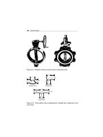
Figure 9.4 Butterfly valves provide almost unrestricted flow
Straight-flow Angle-flow
Cross-flow
Figure 9.5 Three globe valve configurations: straight-flow, angle-flow, and
cross-flow
Control Valves 185
View A View B
Figure 9.6 Globe valve
When the valve is open, as illustrated in View B of Figure 9.6, the fluid flows
through the space between the edge of the disk and the seat. Since the fluid
flow is equal on all sides of the center of support when the valve is open,
there is no unbalanced pressure on the disk to cause uneven wear. The rate
at which fluid flows through the valve is regulated by the position of the
disk in relation to the valve seat.
The globe valve should never be jammed in the open position. After a valve is
fully opened, the handwheel or actuating handle should be closed approx-
imately one-half turn. If this is not done, the valve may seize in the open
position making it difficult, if not impossible, to close the valve. Many valves
are damaged in the manner. Another reason to partially close a globe valve
is because it can be difficult to tell if the valve is open or closed. If jammed
in the open position, the stem can be damaged or broken by someone who
thinks the valve is closed.
Performance
Process-control valves have few measurable criteria that can be used to deter-
mine their performance. Obviously, the valve must provide a positive seal
when closed. In addition, it must provide a relatively laminar flow with min-
imum pressure drop in the fully open position. When evaluating valves, the
following criteria should be considered: capacity rating, flow characteristics,
pressure drop, and response characteristics.
Capacity Rating
The primary selection criterion of a control valve is its capacity rating.
Each type of valve is available in a variety of sizes to handle most typical
186 Control Valves
process-flow rates. However, proper size selection is critical to the per-
formance characteristics of the valve and the system where it is installed.
A valve’s capacity must accommodate variations in viscosity, temperature,
flow rates, and upstream pressure.
Flow Characteristics
The internal design of process-control valves has a direct impact on the flow
characteristics of the gas or liquid flowing through the valve. A fully open
butterfly or gate valve provides a relatively straight, obstruction-free flow
path. As a result, the product should not be affected.
Pressure Drop
Control-valve configuration impacts the resistance to flow through the valve.
The amount of resistance, or pressure drop, will vary greatly, depending on
type, size, and position of the valve’s flow-control device (i.e. ball, gate,
disk). Pressure-drop formulas can be obtained for all common valve types
from several sources (e.g., Crane, Technical Paper No. 410).
Response Characteristics
With the exception of simple, manually controlled shutoff valves, process-
control valves are generally used to control the volume and pressure of
gases or liquids within a process system. In most applications, valves are
controlled from a remote location through the use of pneumatic, hydraulic,
or electronic actuators. Actuators are used to position the gate, ball, or disk
that starts, stops, directs, or proportions the flow of gas or liquid through
the valve. Therefore, the response characteristics of a valve are determined,
in part, by the actuator. Three factors critical to proper valve operation
are: response time, length of travel, and repeatability.
Response Time
Response time is the total time required for a valve to open or close to a
specific set-point position. These positions are fully open, fully closed, and
any position in between. The selection and maintenance of the actuator
used to control process-control valves have a major impact on response
time.
Length of Travel
The valve’s flow-control device (i.e., gate, ball, or disk) must travel some
distance when going from one set point to another. With a manually
operated valve, this is a relatively simple operation. The operator moves
Control Valves 187
the stem lever or handwheel until the desired position is reached. The only
reasons a manually controlled valve will not position properly are mechani-
cal wear or looseness between the lever or handwheel and the disk, ball, or
gate. For remotely controlled valves, however, there are other variables that
directly impact valve travel. These variables depend on the type of actuator
that is used. There are three major types of actuators: pneumatic, hydraulic,
and electronic.
Pneumatic Actuators
Pneumatic actuators, including diaphragms, air motors, and cylinders, are
suitable for simple on-off valve applications. As long as there is enough air
volume and pressure to activate the actuator, the valve can be repositioned
over its full length of travel. However, when the air supply required to power
the actuator is inadequate or the process-system pressure is too great, the
actuator’s ability to operate the valve properly is severely reduced.
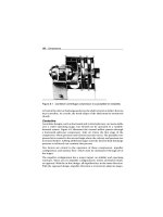
A pneumatic (i.e., compressed air-driven) actuator is shown in Figure 9.7.
This type is not suited for precision flow-control applications, because the
compressibility of air prevents it from providing smooth, accurate valve
positioning.
Hydraulic Actuators
Hydraulic (i.e., fluid-driven) actuators, also illustrated in Figure 9.7, can
provide a positive means of controlling process valves in most applica-
tions. Properly installed and maintained, this type of actuator can provide
Pneumatic or hydraulic
cylinder actuator
Figure 9.7 Pneumatic or hydraulic cylinders are used as actuators
188 Control Valves
Motor
actuato
r
Figure 9.8 High-torque electric motors can be used as actuators
accurate, repeatable positioning of the control valve over its full range of
travel.
Electronic Actuators
Some control valves use high-torque electric motors as their actuator (see
Figure 9.8). If the motors are properly sized and their control circuits are
maintained, this type of actuator can provide reliable, positive control over
the full range of travel.
Repeatability
Repeatability is, perhaps, the most important performance criterion of a
process-control valve. This is especially true in applications where precise
flow or pressure control is needed for optimum performance of the process
system.
New process-control valves generally provide the repeatability required.
However, proper maintenance and periodic calibration of the valves and
their actuators are required to ensure long-term performance. This is
Control Valves 189
especially true for valves that use mechanical linkages as part of the actuator
assembly.
Installation
Process-control valves cannot tolerate solids, especially abrasives, in the
gas or liquid stream. In applications where high concentrations of par-
ticulates are present, valves tend to experience chronic leakage or seal
problems because the particulate matter prevents the ball, disk, or gate
from completely closing against the stationary surface.
Simply installing a valve with the same inlet and discharge size as the piping
used in the process is not acceptable. In most cases, the valve must be larger
than the piping to compensate for flow restrictions within the valve.
Operating Methods
Operating methods for control valves, which are designed to control or
direct gas and liquid flow through process systems or fluid-power circuits,
range from manual to remote, automatic operation. The key parameters that
govern the operation of valves are the speed of the control movement and
the impact of speed on the system. This is especially important in process
systems.
Hydraulic hammer, or the shock wave generated by the rapid change in the
flow rate of liquids within a pipe or vessel, has a serious and negative impact
on all components of the process system. For example, instantaneously
closing a large flow-control valve may generate in excess of three million
foot-pounds of force on the entire system upstream of the valve. This shock
wave can cause catastrophic failure of upstream valves, pumps, welds, and
other system components.
Changes in flow rate, pressure, direction, and other controllable variables
must be gradual enough to permit a smooth transition. Abrupt changes in
valve position should be avoided. Neither the valve installation nor the con-
trol mechanism should permit complete shutoff, referred to as deadheading,
of any circuit in a process system.
Restricted flow forces system components, such as pumps, to operate out-
side of their performance envelope. This reduces equipment reliability and
sets the stage for catastrophic failure or abnormal system performance. In
applications where radical changes in flow are required for normal system
operation, control valves should be configured to provide an adequate
bypass for surplus flow in order to protect the system.
190 Control Valves
Spring
Poppet
Body
No flow
Free flow
In Out
Figure 9.9 One-way, fluid-power valve
For example, systems that must have close control of flow should use two
proportioning valves that act in tandem to maintain a balanced hydraulic
or aerodynamic system. The primary, or master, valve should control flow
to the downstream process. The second valve, slaved to the master, should
divert excess flow to a bypass loop. This master-slave approach ensures that
the pumps and other upstream system components are permitted to operate
well within their operating envelope.
Fluid Power
Fluid power control valves are used on pneumatic and hydraulic systems or
circuits.
Configuration
The configuration of fluid power control valves varies with their intended
application. The more common configurations include: one-way, two-way,
three-way, and four-way.
One-Way
One-way valves are typically used for flow and pressure control in fluid-
power circuits (see Figure 9.9). Flow-control valves regulate the flow of
Control Valves 191
hydraulic fluid or gases in these systems. Pressure-control valves, in the form
of regulators or relief valves, control the amount of pressure transmitted
downstream from the valve. In most cases, the types of valves used for flow
control are smaller versions of the types of valves used in process control.
These include ball, gate, globe, and butterfly valves.
Pressure-control valves have a third port to vent excess pressure and prevent
it from affecting the downstream piping. The bypass, or exhaust, port has
an internal flow-control device, such as a diaphragm or piston, that opens
at predetermined set-points to permit the excess pressure to bypass the
valve’s primary discharge. In pneumatic circuits, the bypass port vents to
the atmosphere. In hydraulic circuits, it must be connected to a piping
system that returns to the hydraulic reservoir.
Two-Way
A two-way valve has two functional flow-control ports. A two-way, sliding
spool directional control valve is shown in Figure 9.10. As the spool moves
back and forth, it either allows fluid to flow through the valve or prevents
it from flowing. In the open position, the fluid enters the inlet port, flows
around the shaft of the spool, and through the outlet port. Because the
forces in the cylinder are equal when open, the spool cannot move back
and forth. In the closed position, one of the spool’s pistons simply blocks
the inlet port, which prevents flow through the valve.
A number of features common to most sliding-spool valves are shown in
Figure 9.10. The small ports at either end of the valve housing provide a
path for fluid that leaks past the spool to flow to the reservoir. This prevents
pressure from building up against the ends of the pistons, which would
hinder the movement of the spool. When these valves become worn, they
may lose balance because of greater leakage on one side of the spool than on
In In
OutOut
Open Closed
Figure 9.10 Two-way, fluid-power valve
192 Control Valves
#1
#1
#1
#2 #3A
#2 #3B
#2 #3C
Figure 9.11 Three-way, fluid-power valve
the other. This can cause the spool to stick as it attempts to move back and
forth. Therefore, small grooves are machined around the sliding surface of
the piston. In hydraulic valves, leaking liquid encircles the piston, keeping
the contacting surfaces lubricated and centered.
Three-Way
Three-way valves contain a pressure port, cylinder port, and return or
exhaust port (see Figure 9.11). The three-way directional control valve is
designed to operate an actuating unit in one direction. It is returned to its
original position either by a spring or the load on the actuating unit.
Four-Way
Most actuating devices require system pressure in order to operate in two
directions. The four-way directional control valve, which contains four
ports, is used to control the operation of such devices (see Figure 9.12).
The four-way valve also is used in some systems to control the operation of
other valves. It is one of the most widely used directional-control valves in
fluid-power systems.
Control Valves 193
Air introduced through
this passage pushes
against the piston
which shifts the
spool to the right
Centering
washers
Springs push against
centering washers to
center the spool when
no air is applied
Pistons seal the air chamber
from the h
y
draulic chamber
Figure 9.12 Four-way, fluid-power valve
The typical four-way directional control valve has four ports: pressure port,
return port, and two cylinder or work (output) ports. The pressure port
is connected to the main system-pressure line, and the return port is con-
nected to the reservoir return line. The two outputs are connected to the
actuating unit.
Performance
The criteria that determine performance of fluid-power valves are similar
to those for process-control valves. As with process-control valves, fluid-
power valves must also be selected based on their intended application and
function.
Installation
When installing fluid power control valves, piping connections are made
either directly to the valve body or to a manifold attached to the valve’s
base. Care should be taken to ensure that piping is connected to the proper
valve port. The schematic diagram that is affixed to the valve body will indi-
cate the proper piping arrangement, as well as the designed operation of
194 Control Valves
the valve. In addition, the ports on most fluid power valves are generally
clearly marked to indicate their intended function.
In hydraulic circuits, the return or common ports should be connected to a
return line that directly connects the valve to the reservoir tank. This return
line should not need a pressure-control device, but should have a check
valve to prevent reverse flow of the hydraulic fluid.
Pneumatic circuits may be vented directly to atmosphere. A return line can
be used to reduce noise or any adverse effect that locally vented compressed
air might have on the area.
Operating Methods
The function and proper operation of a fluid-power valve are relatively
simple. Most of these valves have a schematic diagram affixed to the body
that clearly explains how to operate the valve.
Valves
Figure 9.13 is a schematic of a two-position, cam-operated valve. The pri-
mary actuator, or cam, is positioned on the left of the schematic and any
secondary actuators are on the right. In this example, the secondary actua-
tor consists of a spring-return and a spring-compensated limit switch. The
schematic indicates that when the valve is in the neutral position (right
box), flow is directed from the inlet (P) to work port A. When the cam is
depressed, the flow momentarily shifts to work port B. The secondary actu-
ator, or spring, automatically returns the valve to its neutral position when
the cam returns to its extended position. In these schematics, T indicates
the return connection to the reservoir.
Figure 9.14 illustrates a typical schematic of a two-position and three-
position directional control valve. The boxes contain flow direction arrows
that indicate the flow path in each of the positions. The schematics do not
include the actuators used to activate or shift the valves between positions.
In a two-position valve, the flow path is always directed to one of the work
ports (A or B). In a three-position valve, a third or neutral position is added.
In this figure, a Type 2 center position is used. In the neutral position, all
ports are blocked, and no flow through the valve is possible.
Figure 9.15 is the schematic for the center or neutral position of three-
position directional control valves. Special attention should be given to the
type of center position that is used in a hydraulic control valve. When Type 2,
3, and 6 (see Figure 9.15) are used, the upstream side of the valve must
Control Valves 195
Push rod trips
switch when cam
actuates spool
Roller
(Cam follower)
Spring holds valve
offset in normal
operation
Limit switch
A
ABAB
PTPT
B
“P”
“T”
Figure 9.13 Schematic for a cam-operated, two-position valve
have a relief or bypass valve installed. Since the pressure port is blocked,
the valve cannot relieve pressure on the upstream side of the valve. The
Type 4 center position, called a motor spool, permits the full pressure and
volume on the upstream side of the valve to flow directly to the return line
and storage reservoir. This is the recommended center position for most
hydraulic circuits.
The schematic affixed to the valve includes the primary and secondary actu-
ators used to control the valve. Figure 9.16 provides the schematics for three
actuator-controlled valves:
1 Double-solenoid, spring-centered, three-position valve
2 Solenoid-operated, spring-return, two-position valve
3 Double-solenoid, detented, two-position valve
196 Control Valves
AB
AAABBB
AB
PT
PPPTTT
P
2-Position valve
3-Position valve
T
Figure 9.14 Schematic of two-position and three-position valves
AA ABB B
PPPT
Type 0 Type 1 Type 2
TT
AA ABB B
PPPT
Type 3 Type 4 Type 6
TT
Figure 9.15 Schematic for center or neutral configurations of three-position
valves
Control Valves 197
A
(1)
(2)
(3)
PPPT
PPTT
TT
AAB
A
AABB
PPTT
ABB
BB
Figure 9.16 Actuator-controlled valve schematics
The top schematic, in Figure 9.16, represents a double-solenoid, spring-
centered, three-position valve. When neither of the two solenoids is
energized, the double springs ensure that the valve is in its center or neu-
tral position. In this example, a Type 0 (see Figure 9.15) configuration is
used. This neutral-position configuration equalizes the pressure through
the valve. Since the pressure port is open to both work ports and the return
line, pressure is equalized throughout the system. When the left or primary
solenoid is energized, the valve shifts to the left-hand position and directs
pressure to work port B. In this position, fluid in the A-side of the circuit
returns to the reservoir. As soon as the solenoid is de-energized, the valve
shifts back to the neutral or center position. When the secondary (i.e., right)
solenoid is energized, the valve redirects flow to port A, and port B returns
fluid to the reservoir.
The middle schematic, in Figure 9.16, represents a solenoid-operated,
spring-return, two-position valve. Unless the solenoid is energized, the pres-
sure port P is connected to work port A. While the solenoid is energized,
flow is redirected to work port B. The spring return ensures that the valve
is in its neutral (i.e., right) position when the solenoid is de-energized.
198 Control Valves
The bottom schematic, in Figure 9.16, represents a double-solenoid, deten-
ted, two-position valve. The solenoids are used to shift the valve between its
two positions. A secondary device, called a detent, is used to hold the valve
in its last position until the alternate solenoid is energized. Detent configura-
tion varies with the valve type and manufacturer. However, all configurations
prevent the valve’s control device from moving until a strong force, such as
that provided by the solenoid, overcomes its locking force.
Actuators
As with process-control valves, actuators used to control fluid-power valves
have a fundamental influence on performance. The actuators must provide
positive, real-time response to control inputs. The primary types of actuators
used to control fluid-power valves are: mechanical, pilot, and solenoid.
Mechanical
The use of manually controlled mechanical valves is limited in both pneu-
matic and hydraulic circuits. Generally, this type of actuator is used only on
isolation valves that are activated when the circuit or fluid-power system is
shut down for repair or when direct operator input is required to operate
one of the system components.
Manual control devices (e.g., levers, cams, or palm buttons) can be used as
the primary actuator on most fluid power control valves. Normally, these
actuators are used in conjunction with a secondary actuator, such as a spring
return or detent, to ensure proper operation of the control valve and its
circuit.
Spring returns are used in applications where the valve is designed to stay
open or shut only when the operator holds the manual actuator in a par-
ticular position. When the operator releases the manual control, the spring
returns the valve to the neutral position.
Valves with a detented secondary actuator are designed to remain in the last
position selected by the operator until manually moved to another position.
A detent actuator is simply a notched device that locks the valve in one
of several preselected positions. When the operator applies force to the
primary actuator, the valve shifts out of the detent and moves freely until
the next detent is reached.
Pilot
Although there are a variety of pilot actuators used to control fluid-power
valves, they all work on the same basic principle. A secondary source of fluid
Control Valves 199
or gas pressure is applied to one side of a sealing device, such as a piston or
diaphragm. As long as this secondary pressure remains within preselected
limits, the sealing device prevents the control valve’s flow-control mecha-
nism (i.e., spool or poppet) from moving. However, if the pressure falls
outside of the preselected window, the actuator shifts and forces the valve’s
primary mechanism to move to another position.
This type of actuator can be used to sequence the operation of several con-
trol valves or operations performed by the fluid-power circuit. For example,
a pilot-operated valve is used to sequence the retraction of an airplane’s
landing gear. The doors that conceal the landing gear when retracted can-
not close until the gear is fully retracted. A pilot-operated valve senses the
hydraulic pressure in the gear-retraction circuit. When the hydraulic pres-
sure reaches a pre-selected point that indicates the gear is fully retracted,
the pilot-actuated valve triggers the closure circuit for the wheel-well doors.
Solenoid
Solenoid valves are widely used as actuators for fluid-power systems. This
type of actuator consists of a coil that generates an electric field when ener-
gized. The magnetic forces generated by this field force a plunger that is
attached to the main valve’s control mechanism to move within the coil.
This movement changes the position of the main valve.
In some applications, the mechanical force generated by the solenoid coil
is not sufficient to move the main valve’s control mechanism. When this
occurs, the solenoid actuator is used in conjunction with a pilot actuator.
The solenoid coil opens the pilot port, which uses system pressure to shift
the main valve.
Solenoid actuators are always used with a secondary actuator to provide pos-
itive control of the main valve. Because of heat buildup, solenoid actuators
must be limited to short-duration activation. A brief burst of electrical energy
is transmitted to the solenoid’s coil, and the actuation triggers a movement
of the main valve’s control mechanism. As soon as the main valve’s position
is changed, the energy to the solenoid coil is shut off.
This operating characteristic of solenoid actuators is important. For exam-
ple, a normally closed valve that uses a solenoid actuation can only be open
when the solenoid is energized. As soon as the electrical energy is removed
from the solenoid’s coil, the valve returns to the closed position. The reverse
is true of a normally open valve. The main valve remains open, except when
the solenoid is energized.
200 Control Valves
The combination of primary and secondary actuators varies with the specific
application. Secondary actuators can be another solenoid or any of the other
actuator types that have been previously discussed.
Troubleshooting
Although there are limited common control valve failure modes, the dom-
inant problems are usually related to leakage, speed of operation, or com-
plete valve failure. Table 9.1 lists the more common causes of these failures.
Table 9.1 Common failure modes of control valves
THE PROBLEM
THE CAUSES
Valve fails to open
Valve fails to close
Leakage through valve
Leakage around stem
Excessive pressure drop
Opens/closes too fast
Opens/closes too slow
Manually actuated
Dirt/debris trapped in valve seat • •
Excessive wear • •
Galling • •
Line pressure too high • • • • •
Mechanical damage • •
Not packed properly •
Packed box too loose •
Packing too tight • •
Threads/lever damaged • •
Valve stem bound • •
Valve undersized • •
Control Valves 201
Table 9.1 continued
THE PROBLEM
THE CAUSES
Valve fails to open
Valve fails to close
Leakage through valve
Leakage around stem
Excessive pressure drop
Opens/closes too fast
Opens/closes too slow
Pilot actuated
Dirt/debris trapped in valve seat • • •
Galling • •
Mechanical damage (seals, seat) • • •
Pilot port blocked/plugged • • •
Pilot pressure too high • •
Pilot pressure too low • • •
Solenoid actuated
Corrosion • • •
Dirt/debris trapped in valve seat • • •
Galling • •
Line pressure too high • • • • •
Mechanical damage • • •
Solenoid failure • •
Solenoid wiring defective • •
Wrong type of valve (N-O, N-C) • •
Special attention should be given to the valve actuator when conducting
a root cause failure analysis. Many of the problems associated with both
process and fluid-power control valves are really actuator problems.
In particular, remotely controlled valves that use pneumatic, hydraulic, or
electrical actuators are subject to actuator failure. In many cases, these
202 Control Valves
failures are the reason a valve fails to properly open, close, or seal. Even with
manually controlled valves, the true root cause can be traced to an actuator
problem. For example, when a manually operated process-control valve is
jammed open or closed, it may cause failure of the valve mechanism. This
over-torquing of the valve’s sealing device may cause damage or failure of
the seal, or it may freeze the valve stem. Either of these failure modes results
in total valve failure.
10 Conveyors
Conveyors are used to transport materials from one location to another
within a plant or facility. The variety of conveyor systems is almost infi-
nite, but the two major classifications used in typical chemical plants are
pneumatic and mechanical. Note that the power requirements of a
pneumatic-conveyor system are much greater than for a mechanical con-
veyor of equal capacity. However, both systems offer some advantages.
Pneumatic
Pneumatic conveyors are used to transport dry, free-flowing, granular mate-
rial in suspension within a pipe or duct. This is accomplished by the use
of a high-velocity air stream, or by the energy of expanding compressed
air within a comparatively dense column of fluidized or aerated material.
Principal uses are: (1) dust collection; (2) conveying soft materials, such
as flake or tow; and (3) conveying hard materials, such as fly ash, cement,
and sawdust. The primary advantages of pneumatic-conveyor systems are
the flexibility of piping configurations and the fact that they greatly reduce
the explosion hazard. Pneumatic conveyors can be installed in almost any
configuration required to meet the specific application. With the exception
of the primary driver, there are no moving parts that can fail or cause injury.
However, when used to transport explosive materials, there is still some
potential for static charge buildup that could cause an explosion.
Configuration
A typical pneumatic-conveyor system consists of Schedule-40 pipe or duct-
work, which provides the primary flow path used to transport the conveyed
material. Motive power is provided by the primary driver, which can be a
fan, fluidizer, or positive-displacement compressor.
Performance
Pneumatic conveyor performance is determined by the following factors:
(1) primary-driver output; (2) internal surface of the piping or ductwork;
and (3) condition of the transported material. Specific factors affecting
performance include motive power, friction loss, and flow restrictions.
204 Conveyors
Motive Power
The motive power is provided by the primary driver, which generates the
gas (typically air) velocity required to transport material within a pneumatic-
conveyor system. Therefore, the efficiency of the conveying system depends
on the primary driver’s operating condition.
Friction Loss
Friction loss within a pneumatic-conveyor system is a primary source of
efficiency loss. The piping or ductwork must be properly sized to minimize
friction without lowering the velocity below the value needed to transport
the material.
Flow Restrictions
An inherent weakness of pneumatic-conveyor systems is their potential for
blockage. The inside surfaces must be clean and free of protrusions or other
defects that can restrict or interrupt the flow of material. In addition, when
a system is shut down or the velocity drops below the minimum required
to keep the transported material suspended, the product will drop out or
settle in the piping or ductwork. In most cases, this settled material would
compress and lodge in the piping. The restriction caused by this compacted
material will reduce flow and eventually result in a complete blockage of
the system.
Another major contributor to flow restrictions is blockage caused by sys-
tem backups. This occurs when the end point of the conveyor system (i.e.,
storage silo, machine, or vessel) cannot accept the entire delivered flow of
material. As the transported material backs up in the conveyor piping, it
compresses and forms a solid plug that must be manually removed.
Installation
All piping and ductwork should be as straight and short as possible. Bends
should have a radius of at least three diameters of the pipe or ductwork.
The diameter should be selected to minimize friction losses and maintain
enough velocity to prevent settling of the conveyed material. Branch lines
should be configured to match as closely as possible the primary flow direc-
tion and avoid 90-degree angles to the main line. The area of the main
conveyor line at any point along its run should be 20 to 25% greater than
the sum of all its branch lines. When vertical runs are short in proportion
to the horizontal runs, the size of the riser can be restricted to provide
Conveyors 205
additional velocity if needed. If the vertical runs are long, the primary or a
secondary driver must provide sufficient velocity to transport the material.
Clean-outs, or drop-legs, should be installed at regular intervals throughout
the system to permit foreign materials to drop out of the conveyed material.
In addition, they provide the means to remove materials that drop out when
the system is shut down or air velocity is lost. It is especially important to
install adequate clean-out systems near flow restrictions and at the end of
the conveyor system.
Operating Methods
Pneumatic-conveyor systems must be operated properly to prevent chronic
problems, with the primary concern being to maintain constant flow and
velocity. If either of these variables is permitted to drop below the system’s
design envelope, partial or complete blockage of the conveyor system will
occur.
Constant velocity can be maintained only when the system is operated
within its performance envelope and when regular clean-out is part of the
normal operating practice. In addition, the primary driver must be in good
operating condition. Any deviation in the primary driver’s efficiency reduces
the velocity and can result in partial or complete blockage.
The entire pneumatic-conveyor system should be completely evacuated
before shutdown to prevent material from settling in the piping or ductwork.
In noncontinuous applications, the conveyor system should be operated
until all material within the conveyor’s piping is transported to its final des-
tination. Material that is allowed to settle will compact and partially block
the piping. Over time, this will cause a total blockage of the conveyor system.
Mechanical
There are a variety of mechanical-conveyor systems used in chemical plants.
These systems generally are comprised of chain- or screw-type mechanisms.
Chain
A commonly used chain-type system is a flight conveyor (e.g., Hefler
conveyor), which is used to transport granular, lumpy, or pulverized mate-
rials along a horizontal or inclined path within totally enclosed ductwork.
206 Conveyors
The Hefler systems generally have lower power requirements than the
pneumatic conveyor and have the added benefit of preventing product
contamination. This section focuses primarily on the Hefler-type conveyor
because it is one of the most commonly used systems.
Configuration
The most common chain conveyor uses a center- or double-chain configura-
tion to provide positive transfer of material within its ductwork. Both chain
configurations use hardened bars or U-shaped devices that are an integral
part of the chain to drag the conveyed material through the ductwork.
Performance
Data used to determine a chain conveyor’s capacity and the size of material
that can be conveyed are presented in Table 10.1. Note that these data are
for level conveyors. When inclined, capacity data obtained from Table 10.1
must be multiplied by the factors provided in Table 10.2.
Installation
The primary installation concerns with Hefler-type conveyor systems are the
ductwork and primary-drive system.
Ductwork
The inside surfaces of the ductwork must be free of defects or protrusions
that interfere with the movement of the conveyor’s chain or transported
product. This is especially true at the joints. The ductwork must be sized to
provide adequate chain clearance but should not be large enough to have
areas where the chain-drive bypasses the product.
Table 10.1 Approximate capacities of chain conveyors
Flight Quantity of Approximate Lump size Lump size
width and material capacity single dual
depth (Ft
3
/Ft) (short tons/ strand strand
(inches) hour) (inches) (inches)
12 × 6 0.40 60 31.5 4.0
15 × 6 0.49 73 41.5 5.0
18 × 6 0.56 84 5.0 6.0
24 × 8 1.16 174 10.0
30 × 10 1.60 240 14.0
36 × 12 2.40 360 16.0
Conveyors 207
Table 10.2 Capacity correction factors for inclined chain conveyors
Inclination, degrees 20 25 30 35
Factor 0.9 0.8 0.7 0.6
A long horizontal run followed by an upturn is inadvisable because of
radial thrust. All bends should have a large radius to permit smooth tran-
sition and to prevent material buildup. As with pneumatic conveyors, the
ductwork should include clean-out ports at regular intervals for ease of
maintenance.
Primary-Drive System
Most mechanical conveyors use a primary-drive system that consists of an
electric motor and a speed-increaser gearbox.
The drive-system configuration may vary, depending on the specific applica-
tion or vendor. However, all configurations should include a single-point-
of-failure device, such as a shear pin, to protect the conveyor. The shear pin
is critical in this type of conveyor because it is prone to catastrophic fail-
ure caused by blockage or obstructions that may lock the chain. Use of the
proper shear pin prevents major damage from occurring to the conveyor
system.
For continuous applications, the primary-drive system must have adequate
horsepower to handle a fully loaded conveyor. Horsepower requirements
should be determined based on the specific product’s density and the
conveyor’s maximum-capacity rating.
For intermittent applications, the initial startup torque is substantially
greater than for a continuous operation. Therefore, selection of the drive
system and the designed failure point of the shear device must be based
on the maximum startup torque of a fully loaded system. If either the drive
system or designed failure point is not properly sized, this type of conveyor
is prone to chronic failures. The predominant failures are frequent break-
age of the shear device and trips of the motor’s circuit breaker caused by
excessive startup amp loads.
Operating Methods
Most mechanical conveyors are designed for continuous operation and may
exhibit problems in intermittent-service applications. The primary problem
is the startup torque for a fully loaded conveyor. This is especially true
208 Conveyors
for conveyor systems handling material that tends to compact or compress
upon settling in a vessel, such as the conveyor trough.
The only positive method of preventing excessive startup torque is to ensure
that the conveyor is completely empty before shutdown. In most cases, this
can be accomplished by isolating the conveyor from its supply for a few
minutes prior to shutdown. This time delay permits the conveyor to deliver
its entire load of product before it is shut off.
In applications where it is impossible to completely evacuate the conveyor
prior to shutdown, the only viable option is to jog, or step start, the con-
veyor. Step starting reduces the amp load on the motor and should control
the torque to prevent the shear pin from failing.
If instead of step starting, the operator applies full motor load to a stationary,
fully loaded conveyor, one of two things will occur: (1) the drive motor’s
circuit breaker will trip as a result of excessive amp load, or (2) the shear pin
installed to protect the conveyor will fail. Either of these failures adversely
impacts production.
Screw
The screw, or spiral, conveyor is widely used for pulverized or granu-
lar, noncorrosive, nonabrasive materials in systems requiring moderate
capacities, distances not more than about 200 feet, and moderate inclines
(≤ 35 degrees). It usually costs substantially less than any other type of
conveyor and can be made dust-tight by installing a simple cover plate.
Abrasive or corrosive materials can be handled with suitable construction
of the helix and trough. Conveyors using special materials, such as hard-
faced cast iron and linings or coatings, on the components that come into
contact with the materials can be specified in these applications. The screw
conveyor will handle lumpy material if the lumps are not large in proportion
to the diameter of the screw’s helix.
Screw conveyors may be inclined. A standard-pitch helix will handle material
on inclines up to 35 degrees. Capacity is reduced in inclined applications
and Table 10.3 provides the approximate reduction in capacity for various
inclines.
Table 10.3 Screw conveyor capacity reductions for inclined applications
Inclination, degrees 10 15 20 25 30 35
Reduction in capacity, % 10 26 45 58 70 78