21st Century Manufacturing Episode 1 Part 7 pdf
Bạn đang xem bản rút gọn của tài liệu. Xem và tải ngay bản đầy đủ của tài liệu tại đây (568.37 KB, 20 trang )
114
Product Design, Computer Aided Design (CAD), and Solid Modeling Chap. 3
start-up company needing a modest CAD environment would also be wise to invest
in these products, which include but are not limited to:
• AutoCAD commercially available from <www.autodesk.com>
• SolidWorks commercially available from <www.solidworks.com>
• IronCAD commercially available from <www.ironcad.com>
3.12.3
Systems with
"'High
Overhead"
The next group of products have been built to do high-end solid modeling with real-
time rendering, and they maintain a parametric model of the emerging design. This
means that objects are initially created generically without specific dimensions.
When objects are specifically instantiated, dimensions are added and everything
scales up or down to suit. The user is able to define constraints between different
parts of an object and then scale them.
For long-term company growth over several product variants this has enor-
mous appeal. However, there is a major drawback. There is a huge learning time for
such systems. Also, since they are updated every 18 months or so, further retraining
on new "revs" is likely.
These are powerful design tools for a large automobile company or a national
laboratory. In these environments, many similar components in a family are being
designed. Their use in a bearing-manufacturing company like TImken Inc. is perhaps
the easiest to visualize. Bore sizes, races, cover plates, and the like, can be created
once and then "scaled up or down." For future revisions of a component, any existing
parametric designs that might reside in a software library can quickly be reinstanti-
ated to create a new object in the same family.
These larger systems also have direct links to supplementary packages that
will do
DFM/A
and finite-element analysis. Most of them also include a CORBA-
based open architecture that allows linking to other software applications (e.g.,
SDRC, 1996).
• ProEngineer commercially available from <www.ptc.com>
• IDEAS commercially available from <www.sdrc.com>
• Unigraphics commercially available from <www.ugsolutions.com>
• CATIA commercially available from <www.catia.com>
Translations between these different commercial CAD systems were once done with
initial graphics exchange system (IGES) and can now be done with product defini-
tion exchange system (PDES/STEP). PDESISTEP is evolving into a useful world-
wide standard (see ISU, lY/:iY,lYY3).
Other products such as Spatial Technology's ACIS (ACIS, 1993) play an inter-
mediate role compared with the aforementioned applications. They have specialized
in the "market niche" of creating an open de facto standard for solid representations.
This is finding adoptions in other systems, including AutoCAD. The openness of
ACIS is popular with the research community. From a management of technology
viewpoint this direction toward open CAD systems is important.
3.12 Management of Technology
115
3.12.4
Current Trends in CAD
The CAD field is developing very quickly indeed. At the time of this writing,"stu-
dent editions" of PTC's Pro-Engineer and SDRC's IDEAS are becoming available
for only $100. Thus, even these more sophisticated systems are becoming more
readily available to the average user and are able to run on modest computer sys-
tems in the $1,500to $3,000price range for a well-configuredenvironment. This still
does not mean an end user should "jump right in" and use them. The bigissues-dis-
cussed above-are the "learning curve" and the "library creation for parametric sys-
tems." These trade-offs are captured in Figure 3.32. On the other hand, used in a
nonparametric way, these higher end packages can create excellent feature-based
models.The governing factor seems to "boil down" to how much long-term interest
a person or group has in using CAD tools. Here are three scenarios:
•For a start-up company,where a CAD system might be used only once to gen-
erate an idea and then an FDM prototype, the cheaper nonparametric
approach is recommended.
•Also in small,newer companies, today's evidence is that the turnover among
young engineers is high. It might not be worth investing the training time
needed for the full parametric systems when quite satisfactory designs can be
done with the cheaper systems like AutoCAD, SolidWorks,and so on, which
have a short learning curve.
•But for large, stable companies, if several product revisions will be
designed spanning several months or years, then the time invested in
learning the parametric approach in ProEngineer, SDRC, and the like, will
be worthwhile.
3.12.5
Future Trends in CAD: Multidisciplinary Concurrent
Design/Engineering and Global Manufacturing
For a variety of cultural reasons, today's industrial growth is more and more
dependent on situations where
large businesses are distributed.
Often these large
business organizations are split up but then orchestrated over several continents,
perhaps to take advantage of excellent design teams in one country and low-cost,
efficient manufacturing teams in another. These trends place even more emphasis on
concurrent engineering (or simultaneous design) and design for manufacturability
and assembly
(DFMlA).
The goals are to coordinate all members of a design and
manufacturing team at each stage ofproduct development, manufacturing, sales,and
service (see Urban et aI.,1999).
To further complicate such trends, engineering products are more complex.
Concurrent engineering is difficult enough when the product is nearly all mechan-
ical (such as a gear box) or nearly all electronic (such as a television). But as auto-
mobiles,aircraft, robots, and computers become a highlycomplex mix of integrated
circuits, power supplies, controllers, and mechanical actuators, concurrent engi-
neering becomes even more challenging. It clearly demands the orchestration of
'i[lliJ
~
~
~
o
NP cr FE PF
{IN]
NP
cr
FE
Fipn
3.32 'Irade-offe between nonparametric systems, parametric constraint-based, full feature-based,
and part family CAD systems (courtesy of 1.1.Shah).
Legend
NP
=
Nonparametric
Cj'
e
Consrraint
based
FE = Feature
based
PF= Part
families
PF
100
m
]
s
.~~
OJ
o
NPCfFE PF
NP
cr
FE PF
3.13 Glossary
117
multidisciplinary design teams. These trends will create the need for environments
that allow, for example:
•The integration of electrical-CAD tools with mechanical·CAD tools. Chapter 6
describes a domain unified computer aided design environment (DUCADE)
that facilitates multidisciplinary concurrent design for consumer electronic
products.
•The creation of intelligent
agents
for Internet-based design. An example might
be an agent for plastic injection-mold design (Urabe and Wright, 1997).
Internet-based design environments allow the original part designer to import
information on specific "downstream" processes-in this case, how to fabri-
cate negative mold halves. Information could also include data on shrinkage
factors, recommended draft angles for the mold, and snap fit geometries
(Brock, 2000).
3.13 GLOSSARY
3.13.1
Boundary Edge Representation
Boundary representations, or
b-reps,
describe an object in terms of its surface bound-
aries: vertices, edges, and faces.
3.13.2 Creative Design
The formative, early phases of the design process, where market identification, con-
cepts, and general form are studied.
3.13.3
Constructive Solid Geometry (CSG)
The addition, subtraction, or intersection of simpler blocklike primitives to create
more complex shapes.
3.13.4
Destructive Solid Geometry (DSG)
A special case of CSG where the designer begins with "graphical stock" and changes
its shape with only the subtraction
01
intersection commands, in order to suit later
operations on a "downstream" machine tool.
3.13.5
Detail Design
The later phases of design in which specific shapes, dimensions, and tolerances are
specified on a CAD system.
3.13.6
Design for Assembly, Menufaeturability, end the
Environment
The collection of terms used to encourage designers to adjust their design activities
for ease of assembly (OFA), manufacturing (DFM), or environmentally conscious
(E) issues. Often
DFX
is used to summarize all these "design for" activities.
118 Product Design, Computer Aided Design (CAD), and Solid Modeling Chap. 3
3.13.7 Feature-Based Design
The use of specific primitive shapes in design that suit a particular "downstream"
manufacturing process.
3,13.8 Ink-Jet Printing in 3-D
Rapid prototyping by rolling down a layer of powder and hardening it in selected
regions with a binder phase that is printed onto the powder layer.
3.13.9 Injection Molding
Viscous polymer is extruded into a hollow mold (or die) to create a product.
3.13.10 Investment Casting
The word
investment
is used when time and money are invested in a ceramic shell
that is subsequently broken apart and destroyed. The original positive master that is
used to create the negative investment shell can be made by several processes.Lost
wax and ceramic mold are the two most common.
3.13.11 Machining
General manufacturing by cutting on a lathe or mill; chip formation from a solid
block rather than forging, forming, or joining.
3.13.12 Parametric Design
CAD techniques that represent general relationships (e.g.,height-to-width), not nec-
essarily specific dimensions.
3.13.13 Prototyping (Prototypel
"The original thing in relation to any copy,imitation, representation, later specimen
or improved form" (taken from Webster's Dictionary).
3.13.14 Plastic Injection Molding
As "injection molding," described above. Note:Zinc die casting also involves "injec-
tion" into dies or molds.
3.13.15 Personal Digital Assistant (PDA)
Current, fashionable term for several handheld computing devices possibly with
e-mail link, cell phone, and modest display.
3.13.16 Rapid Prototyping IRPI
A new genre of prototyping, usually associated with the SFF family of fabrication
methods. Emphasis is on speed-to-first-model rather than fidelity to the CAD
description.
3.14 References
119
3.13.17 Solid Freeform Fabrication (SFF'
A family of processes in which a CAD file of an object is tessellated, sliced, and sent
to a machine that can quickly build up a prototype layer by layer.
3.13.18 Solid Modeling ("Solids'"
CAD representations that correspond to real-world physical objects with edges, ver-
tices, and faces. A CAD operation on a solid model will be consistent with a physical
action or deformation that could be performed in the physical world. Wire frame
CAD modeling does not guarantee this condition.
3.13.19 Tessellation
Representing the outside surfaces of an object by many small triangles, like a mesh
thrown over and drawn around the object. This leads to an ".STL" file of the vertices
and the surface normals of the triangles.
3.13.20 Wire Frame Modeling
CAD representations that correspond to abstract lines and points. An object can be
drawn and even rendered, but the computer does not store an object that is "under-
stood" in a physical sense.
3.14 REFERENCES
ACIS Geometric Modeler. 1993. Version 1.5. Technical Overview. Boulder, Co. Spatial Tech-
nology,Inc.
Baumgart, B. G. 1972. Winged edge polyhedron representation. Technical Report STAN-CS-
320, Computer Science Department, Stanford University,
Baumgart, B. G. 1975. A polyhedron representation for computer vision. NCC 75: 589-596.
Berners-Lee, T.1989. Information management: A proposal. CERN internal proposal.
Boothroyd, G., and P.Dewhurst. 1999. DFMA software. On CD from the company, or contact
<www.dfmlll.com>.
Braid, l. C. 1979. Notes on a geometric modeler. CAD Group Document, 101, Computer lab-
oratory, University uf Cambridge.
Brock, 1.M. 2000. Snap-fit geometries for injection molding. Master's thesis, University of Cal-
iforrria.Berkeley,
Compton, W. D. 1997. Engineering management, "Creating and managing world class opera-
tions." Upper Saddle River, N.J.: Prentice-Hall.
Cutkosky, M. R., and J. M. Tenenbaum. 1990. A methodology and computational framework
for concurrent product and process design. Mechanism and Machine Theory 25, no. 3: 365 381,
Pinin, T., D. McKay, R. Fritzson, and R. McEntire. 1994. KOML: An information and knowl-
edge exchange protocol. In Knowledge building and knowledge sharing. Edited by Kazuhiro
Fuchi and Toshio Yokoi. Amsterdam, Washington D.C., and Tokyo: Ohmsha and IDS Press.
120
Product Design, Computer Aided Design (CAD), and Solid Modeling Chap. 3
Foley, 1. D.,A. van Dam, S. K. Feiner, and 1.F. Hughes. 1992. Computer graphics: Principles and
practice, 2nd ed., Reading, Mass: Addison Wesley.
Frost, R., and M. Cutkosky. 1996. An agent-based approach to making rapid prototyping
processes manifest to designers. Paper presented at the ASME Symposium on Virtual Design
and Manufacturing.
Grayer,A. R.1976. A computer link between design and manufacture, Ph.D. diss., University
of Cambridge.
Greenfeld,l,EB. Hansen, and P.K. Wright. 1989. Self-sustaining.open-system machine tools.
In Proceedings of the 17th North American Manufacturing Research Institution 17: 281-292.
Hauser, 1. R., and D. Clausing. 1988. The house of quality. Harvard Business Review
(May-June); 63-73.
Hazelrigg, G. 1996. Systems engineering: An approach to information-based design. Upper
Saddle River, N.1.: Prentice-Hall.
Hoffmann, C. M. 1989. Geometric and solid modeling. San Mateo, CA: Morgan Kaufmann.
ISO. 1989. External representation of pro duet definition data (STEP). ISO DP 10303-0.
ISO. 1993. Product data representation and exchange-Part I: Overview and fundamental
principles. ISO DIS 10303-1, TC184JSC4IWG4 N193. Also see the following papers on
PDES/STEP:
Wilson, P. 1989. PDES STEP forward. IEEE Computer Graphics and Application
79-80.
Eastman, C. 1994. Out of STEP? Computer-Aided Design 26, no. 5.
Kamath, R. R., and 1.K. Liker.1994.A second look at Japanese product development. Harvard
Business Review, reprint number 94605.
KimL H., F. C. Wang, C. Sequin, and p.K. Wright. 1999. Design for machining over Internet.
Design Engineering Technical Conference (DETC) on Computer Integrated Engineering,
Paper Number DETC'99/CIE-9082, Las Vegas.
Mead, C, and L. Conway. 1980. The CalTech intermediate form for LSI layout description In
Introduction to VLSI Systems, 115-127. Addison Wesley.
MOSIS. 2000. University of Southern California's Information Sciences Institute-The MOSIS
VLSI Fabrication Service,
edulmosW.
Pratt, M. J., and P.R. Wtlson.1987. Conceptual design of a feature-oriented solid modeler. Draft
Document 3B, General Electric Corporate R&D.
Puttre, M. 1992. Sculpting parts from stored patterns. Mechanical Engineering, 66-70.
Regli, W.
C,
S. K. Gupta, and D. S. Nau. 1995. Extracting alternative machining features: An
algorithmic approach. Research in Engineering Design 7: 173-192.
Requicha, A. A. G. 1977. Mathematical models of rigid solids. Technical memo 28. Production
Automation Project. New York: University of Rochester.
Requicha, A. A. G. 1980. Representations for rigid solids-Theory, methods, and systems. ACM
Computing Surveys, 437-464.
Requicha.A. A. G., and H. B. Voelckcr. 1977.
Constructive solid geometry.
Technical memo 25.
Production Automation Project. New York: University of Rochester.
Richards, B., and R. Brodersen. 1995. InfoPad: The design of a portable multimedia terminal.
In Proceedings of the Mobile Multimedia Conference-2, Bristol, England.
Riesenfeld, R. 1993. Modeling with NURBS curves and surfaces. In Fundamental Develop-
ments of Computer-Aided Geometric Modeling, 77-97. San Diego, CA: Academic Press.
3.15 Bibliography
'21
Roberts, L. G.1963. Machine perception three-dimensional solids. Technical report no. 315. Lin-
coln Laboratory, MIT.
SORe. 1996. The Open-IDEAS Programming Course ManualiMS 5282-5. Milford,OH:
Structural Dynamics Research Corporation.
Sequin,
c.
S. 1997. Virtual prototyping of Scherk-Collins saddle rings. Leonardo 30, no. 2:
89-96.
Shah.
I
1., and M. Mantyla. 1995. Parametric and feature based CAD/CAM. Wiley. NY. (Also
see Shah, 1.J M. Mantyla, and D. S. Nau. 1994. Advances in feature based manufacturing. New
York: Elsevier.)
Sidall, 1.N. 1970. Analytical decision-making in engineering design. Upper Saddle River, N.J.:
Prentice-Hall.
Smith,
C;
and P. K. Wright. 1996. CyberCut: A World Wide Web based design to fabrication
tool. Journal of Manufacturing Systems 15, no. 6:
432 442.
Stcri, 1.A, and P. K. Wrighl. 199". A knowledge based system for machining operation plan-
ning in feature based, open architecture manufacturing. In Proceedings (on Compact Disc) of
the 1996 Design for Manufacturing Conference, University of California, Irvine.
Sub, N. P.1990. The principles of design. New York and Oxford: Oxford University Press.
Sungertekin, LlA, and H. B. Voelcker. 1986. Graphic simulation and automatic verification of
machining programs. In Proceedings Of the IEEE Conference on Robotics and Automation.
Sutherland, I. E. 1963. Sketchpad: A man-machine graphical communication system. In Pro-
ceedings of Spring Joint Computer Conference, 23.
Urabe, K., and P.K. Wright. 1997. Parting planes and parting directions in a CAD/CAM system
for plastic injection molding. Paper presented at the ASME Design for Manufacturing Sym-
posium, the Design Engineering Technical Conferences. Sacramento, CA.
Urban. S. D., K.Ayyaswamy,
L
Fu, 1.1. Shah, and 1.Liang. 1999. Integrated product data envi-
ronment: Data sharing across diverse engineering applications. International Journal of Com-
puter Integrated Manufacturing
12,
no.
6: 525-540.
Woo, T. 1992. Rapid prototyping in CAD. Computer Aided Design
24: 403-404.
Wright, P. K., and D. A. Bourne. 1988. Manufacturing intelligence. Reading, MA: Addison
Wesley.
Wright, P. K., and D. A. Dornfeld. 1996. Agent based manufacturing systems. In Transactions
of the 24th North American Manufacturing and Research Institution, 241-246.
3,'5 BIBLIOGRAPHY
Bartels, R. H., 1.C. Beatty, and B. Barsky. 1987. An introduction to splines for use in computer
graphics and geometric modeling. San Mateo, CA: M. Kaufmann Publishers.
Hyman, B. 1998. Fundamentals of engineering design. Upper Saddle River, N.J.: Prentice-Hall.
Proceedings of the Institute of Mechanical Engineers. 1993. Effective technologies for engi-
neering success-Making CAD/CAM pay. No. 1993-12.
Regli, W. C, and D. M. Gaines. 1997. A repository for design, process planning and assembly.
Computer Aided Design 29, no. 12: 895-905.
Sequin, C. H., and Y. Kalay. 1998. A suite of prototype CAD tools to support early phases of
architectural design. Automation in Construction 7:
449 464.
122 Product Design, Computer Aided Design (CAD), and Solid Modeling Chap. 3
3.16 URLS OF INTEREST: COMMERCIAL CAD/CAM SYSTEMS AND
DESIGN ADVISERS
1. Parametric Technology Corp, Pro/ENGINEER,
2. Autodesk, AutoCAD, bttp://www.autodesk.com
3. SolidWorks, bttp://www.solidworks.com
4. Spatial Technologies, ACIS,
5. 3D/EYE Inc, TriSpectives, -com
6. SDRC, I-DEAS,
7. EDS, Unigraphics,
8. MSC,ARIES,
9. DesignSuite by Inpart, Saratoga, California,
10. Cambridge process selector, bttp:f/www.granta.co.uklproducts.btml
3.17 CASE STUDY
The goal of this case study is to reinforce the four levels of design described in Sec-
tion 3.2. Specific ideas for a novel snow shovel are shown indented below the main
design level. SORC is the design tool being used in the example. Parametric design is
highlighted. Reiterating a point made in the introduction, note that this chapter has
attempted to move through a transition of design tools from simple wire frame to
solid modeling, to solid modeling with rendering, and now to parametric design. Sec-
tion 3.2 summarized four main phases of the design process. These are repeated below
and used to guide the reader into the detailed steps using SDRC's IDEAS system.
1. Art related and high-level: "Design in any of its forms should be functional,
based on a wedding of art and engineering" (W. A. Gropius, founder of the
Bauhaus movement).
The snow shovel will be designed in this case study as an attractive, colorful,
lightweight, foldable device that mountaineers will buy at their local"outdoors shop."
2. Engineering related and high-level: "Design is the process of creating a product
(hardware, software, or a system) that has not existed heretofore" (Suh, 1990).
A collapsible snow shovel is designed inthe next few pages with the purpose
of improving the weight, cost, and usefulness over existing shovels. Emphasis is
placed on the shovel head as the component with the most potential for improve-
ment. The shovels that were found in the marketplace were separated into two pri-
mary design classifications. The first was the plastic shovel, which was lightweight
and cheap but was not hard or stiff enough to be useful in ice or dense snow con-
ditions. The second was the aluminum shovel, which was useful in all conditions
but was significantly heavier and more expensive than a plastic shovel.
3. Engineering related and at the analytical level: "Design is a decision making
process" (Hazelrigg, 1')96).
The new shovel incorporates the best of both shovel designs by combining a
cheap, lightweight shovel scoop made out of polycarbonate with a hard, tough
molded-in cutting blade made from aluminum 6061. Emphasis is placed on stiff-
ening the shovel head through geometric features to allow a reduction in the
3.17 Case Study
123
shovel wall thickness (and thus a weight and cost reduction). This is accomplished
by simulating load conditions using the ANSYS finite element analysis software
and iterating the design to improve it.
4. Detailed design: "Design is to make original plans, sketches, patterns, etc." (Web-
ster's Dictionary).
The first step in the design of the shovel isthe creation ofa wire frame drawing to
be extruded into the initialsolidof the model.The most complex viewofthe part isgen-
erally selected for this wire frame, and in thiscase,the side view ofthe shovelisselected
for the wireframe drawing.The finalshovel design wireframe isshown inFigure 3.33.
Notice the dimensions on the wire frame in Figures 3.33 and 3.34. Unlike
conventional drafting packages where the dimensions are added to document a
specific line length, parametric design controls the size of the part with these
dimensions. They are therefore called constraints rather than dimensions in para-
metric design. Figure 3.34 shows the side view of the wire frame sketch of the
shovel head after the angle constraint has been modified from 32 degrees to 45
degrees. Notice how this simple change dramatically alters the shape of the shovel.
A standard drafting package would require the shovel head to be redrawn and
then redimensioned to make this change. The ability to rapidly change such design
parameters is one of the key strengths of parametric design. Also notice that in addi-
tion to the standard constraints of length, there are constraints for angular, radial,
perpendicular, tangent, and coincident objects in Figures 3.33 and 3.34.
Figure 3.35 shows the solid object from an isometric front view that is created
when the wire frame shown in Figure 3.33 is extruded a distance of 225 millime-
ters (9 inches) and draft angles are added for strength and manutacturabillty.
Figure 3.36 shows the same view after fillets have been added to the shovel head.
The next step in the shovel design is to add cutouts to the bottom of the
shovel head, which will become the stiffening ribs when the part is turned into a
shell. Figure 3.37 shows a view perpendicular to the back edge of the shovel head
Flgure3.33 Wire frame model of
snow shovel (Thanks are due to Dan
Odcllforhiscontributions).
flgure3.34
124 Product Design, Computer Aided Design (CADJ, and Solid Modeling Chap. 3
Ftpn3.35
F1gure3.36
with the wire frame for the rib cutouts sketched on it. The wire frame cutouts
extend past the actual part that they are intended to cut to ensure that they cut
through the entire part.
Figure 3.38 shows an isometric view of the bottom of the shovel after the wire
frame sketch has been extruded at an angle as a cutout to form the inverse of the rib
profile. In a similar way, Figure 3.39 shows an isometric view of the top of the shovel
after it has undergone a shell operation and a filleting operation. The shell operation
takes a solid object and offsets its outer surfaces to generate a part of uniform wall
.•• ,.,
3.17 Case Study
125
thickness. An option in the shell command allows specified surfaces to be removed
from the shell operation, and in this case the top and front surfaces have been
removed to create the scoop shape of the shovel. The shell command is very useful
in design for the injection molding process where a uniform wall thickness is desir-
able to achieve uniform cooling and shrinkage. It can also be useful for processes
such as thermoforming and sheet metal forming where a sheet of uniform thickness
is used as the raw material.
The ribs were added to increase the moment of inertia of the shovel in the
direction ofthe expected snow load and thereby to stiffen the shovel head. Stiffening
the shovel through geometric changes allows a reduction in overall wall thickness,
which relates to a reduction in cost and weight. Notice how the use of the shell com-
mand greatly simplifies the design of these ribs, which would have been quite diffi-
cult to model without use of this command.
The next step in the design of the shovel head is to add the interface
between the shovel head and the shaft. The wire frame sketch of this interface
is shown in Figure 3.40. To make this sketch and locate it properly, a reference
plane has been added to the shovel. This plane is placed to be perpendicular to
the rear face of the shovel so that wire frames that will be sketched and extruded
••••••,.40
126
Product Design, Computer Aided Design (CAD), and Solid Modeling Chap. 3
•
f1#1Jre3Al
Figure3A2
Figure;,t44
on it will be parallel to the rear of the shovel. Onto this plane, the outermost
lines of the shovel head have been
focused
to give a reference for centering the
interface. The interface is sketched as a tubelike structure to create a slip-fit with
the shaft.
Figure 3.41shows the shovel head after the interface section is extruded. This
interface isextruded to a distance so that its full length extends past the shovel head.
The interface is then cut off at an angle to match the bottom of the shovel. It is also
lengthened, and the remaining wall of the shovel head inside the tube is removed.
The result of these operations is shown in Figures 3.42 and 3.43.
Next, as shown in Figure 3.44, the resulting hole on the bottom of the
shovel is sealed. and a hole is added for the fastener that attaches the shovel
head to the shaft. This step completes the design of the shovel scoop itself. The
next step is to add the molded-in aluminum cutting blade. Figure 3.45 shows a
bottom view of the shovel with a wire frame sketch of the plastic section that
will encase the cutting blade. Once this section is extruded, the wire frame for
the blade itself is generated as in the bottom front isometric view in Figure 3.46.
Notice that in this case the blade is drawn as an integral component of the shovel
head. Later, a second model of the blade will have to be generated that includes
the section that is encased in the plastic. This section will require several slots so
that during injection molding, the plastic will flow through them and mechani-
cally entrap the blade.
3.17 Case Study
Figure 3,45
FIgure 3.47
127
l!'igure3AS
Once the blade is extruded, the remaining fillets are added to the part and the
design iscomplete. The top and bottom isometric views of the completed shovel are
shown in Figures 3.47 and 3.48.
It is important to note that the strength of parametric design is the ability to
rapidly modify steps in the design to improve the final design. The steps that are doc-
umented for this case study are for the final shovel design, but many intermediate
designs were modified to obtain the final one. If something inthis design were found
to be inadequate, any of these steps in the design could be reached and modified by
accessing the "history tree" of the part.
For this design, the step of greatest interest was the design of the stiffening ribs.
To help optimize these ribs, the solid model of the shovel head was imported into the
ANSYS finite element analysis software and the loading was simulated under var-
ious conditions. Figure 3.49 shows this simulation for stress under a buckling load.
This load produced the worst results for the shovel but is not expected to be encoun-
tered often, and the addition of the metal blade (which is not modeled in this simu-
lation) will help to relieve some of this stress.
128 Product Design, Computer Aided Design (CADl, and Solid Modeling Chap. 3
.••
,
3.18 QUESTION FOR REVIEW
1. For Figure 3.50, give the CSG representation in the form of a CSG tree using the
two basic primitives of a cylinder and a block with their local coordinates as
shown. The origin of the world coordinates should be taken at the base of the
cylindrical hole as shown. Any translations or rotations required must be clearly
shown in the CSG tree.
R. Does the point P(6,0,3) lie in the object? Clearly show all necessary calculations
using the esc tree to makeconclusions.
b. After having marked all the vertices, determine how many edges and faces the
object had.
Co
eSG representationisnot unique.Provethis statementby creating anotherCSG lree
for the aboveobject.Use different-sizedshapes.(Cylindersmay be the same size.)
3.1
B
Question for
RS"'w
z
tEV
Ftgure 3.50
Example
fOI
CSG question.
CHAPTER
4.1 SOLID FREEFORM FABRICATION (SFFI METHODS
Several manufacturing processes are available to make the important transition
from computer aided design (CAD) to a prototype part. Several new technologies
began to make their appearance after 1987. In that year, stereolithography (SLA)
was first introduced by 3D Systems Inc., and over the next five years several rival
methods also appeared.This created the family of processes known as solid freeform
fabrication (SFF). As with most new technologies at the beginning of the "market
adoption S-shaped curves" in Chapter 2, the SFF domain is accompanied by a rela-
tive amount of advertising "hype." SFF processes are sometimes described as:
• Parts on demand
• From art to part
• Desktop manufacturing
• Rapid prototyping
At the time of this writing, stereolithography (SLA), selective laser slntering
(SLS), fused deposition modeling (FDM), and layered object modeling (LOM) are
being used on a day-to-day basis by commercial prototyping companies. The three-
dimensional (3-D) printing process in cornstarch, plastic, and ceramics is also heing
used commercially. The methods lower on the list show promise but do not seem to
be in great use by third party prototyping houses to make their daily income. Casting
is a special case. It is still used to make one-of-a-kind prototypes. Furthermore, for
batch runs in the 10 to 500 category it is a very cost effective method to use once an
original mold has been made by a process such as stereolithography Machining is
also used to make one-of-a-kind or several prototypes.
130
SOLID FREEFORM
FABRICATION (SFF)
.AND RAPID PROTOI¥-PING
4.1 Solid Freeform Fabrication (SFF) Methods
131
4.1.1 Summary of SFF and Rapid Prototyping Processes
In daily commercial use:
• Stereolithography (SLA)
• Selective laser sintering (SLS)
• Laminated object modeling (LOM)
• Fused deposition modeling (FDM)
More at the research and development (R&D) stage:
• 3-D printing in cornstarch, plastic, or ceramic
• 3-D printing with plastics followed by planarization using machining
• Solid ground curing (similar to SLA)
• Shape deposition modeling (a combination of addition and subtraction)
Non-SFF (traditional):
•Machining
• Casting
Comparisons done in the early 1990s by the Chrysler Corporation revealed
that the SLA process was ahead of its rival nontraditional prototyping methods in
terms of cost and accuracy (these studies excluded an evaluation of machining and
casting). Following the technical descriptions in this chapter, additional figures and
tables are thus included to compare these costs and accuracies. Over the last decade,
SLA has further emerged as the most used SFF process, especially for the generation
of the master patterns for casting and injection molding. At the time of this writing,
SLS,FDM, and LOM have the most visibility after SLA.
4.1.2 The History of SFF Methods
During the late 19705,Mead and Conway (1980) created the groundwork for the fast
prototyping of very large scale integrated (VLSI) circuits. Designers were encour-
aged to think in terms of five two-dimensional (2-D) patterns. These patterns defined
three stacked interconnection layers on a metal-oxide-semiconductor (MOS) wafer
and their mutual connections through holes.The patterns described the actual geom-
etry of the connection runs and via holes that one would see when looking down onto
the circuit chip, regardless of the exact process and number of masking steps that
were used to implement the chip (see MOSIS, 20(0).
Inspired by this success, beginning in the 19705,several companies tried to
create layered manufacturing for mechanical parts. Also by the mid-1980s, several
U.S. government studies analyzed the possibilities of a "mechanical MOSI$" (Man-
ufacturing Studies Board, 1990;Bouldin, 1994;NSF Workshop I, 1994,and II, 1995).
The prospects for a mechanical MOSIS were thus frequently linked to the fab-
rication processes in the lists mentioned (Ashley, 1991,1998;Heller, 1991;Kruth, 1991;
Woo, 1992, 1993;Au and Wright, 1993; Kochan, 1993;Kai,I994; UCLA, 1994;Weiss
132
Solid Freeform Fabrication (SFF) and Rapid Prototyping Chap. 4
and Prinz, 1995;Cohen et
al.,
1995;Dutta, 1995;Jacobs, 1992, 1996; Beaman et al., 1997;
Kumar et al., 1998; Sachs et al., 2000).
The introduction of the first commercial SFF technology-stereolithography-
was accompanied by the advent of the STereoLithography (.STL) representation of
a
CAD
object. ".STL" is a modified CAD format that suits a subsequent slicing oper-
ation and the "downstream" laser-scanning paths on a physical SLA, FDM, or SLS
machine.
Is a soccer ball round? The answer depends on how carefully the ball is meas-
ured. Nominally, it is a perfect sphere. However, on closer inspection, the leather is
sewn together from about 20 little hexagonal patches and a few pentagonal patches
to create the curvature. In reality it is an approximation to a sphere.
Likewise, the" .STL" format approximates the boundary surfaces of a CAD
model by breaking it down into interconnected small triangles-a process called tes-
sellation. Each triangle isrepresented by the x/y/z coordinates of each of its three ver-
tices, enumerated by the right-hand rule-that is, counterclockwise (ccw) order as
viewed from the outside of the body.The vector normal to the surface of each triangle
is also specitied.This tessellated surface is stored as an
".STL
file." This file, perhaps
containing up to 200,000 triangles, is sent over the Internet to a prototyping shop.
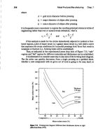
As shown in Figure 4.1, this tessellated CAD model is then sliced like a stack
of playing cards. For 3D Systems' machines this is known as the
SLI
or sliced file.
Other rapid prototyping machines use the slicing technique but have their own file
creation details and names. Each slice for the imaginary soccer ball will thus be a
circle. However, because of the tessellation procedure it will not be a perfect circle.
The slicing action cuts through the triangles on the boundary. Thus, each circular slice
(or disc) will actually be a multisided polygon running inside the "bounding circle."
The number of sides on this inner polygon is of course related to how finely divided
the original tessellation was made.
Inside the SLA machine, the laser first creates the outer boundary ofeach slice
and then "weaves" across each slice in a hatching pattern to create the layer. The
number of slices and the style of the weaving pattern are chosen by each rapid pro-
totyping shop. Especially for SLA and SLS a certain amount of trial and error, or
crattspersonship, begins to playa role at this stage. This is reviewed in more detail
over the next few pages.
".STL" is now the standard exchange format for SFF processes. However, it is
inadequate for many reasons. First, the files are large due to the tessellation method.
Second, there are redundancies in the" .STL" format. One example of redundancy is
as follows: the triangles are represented by the "counterclockwise rule" so that it is
clear in which direction the outer-surface normal acts. However, it has also become
customary to specify the surface vector as well. Inconsistency can be introduced as a
result of this redundancy, and no rules exist for resolving it.
McMains (1996) describes how ".STL" does not capture topology or connec-
tivity, making it difficult to fix some of the common errors found in files-c-such as
cracks, penetrating or extraneous faces, and inconsistent surface normals-without
resorting to guessing the designer's original intent. More general digital interchange
formats have also been used with SFF.These inciudeACIS (1993) and IGES (Heller,
1991). However, as described in NSF (1995),problems arise with these formats, too.
4.2 Stereolithography: A General Overview
'33
Materialaddition processes
CAD
AUIOfllillicpl'OCtSSpilll'lllef
Automatcd tabncauon rnachine
(hi
Fipre 4.1 An ~
.STL" file
is
a tessellated object. The top
figure
shows
a
contact
lens holder represented hy many surface patches. The ".STL" file is then sliced.
Laser motions then harden the part (courtesy of Lee Weiss).
One aspect of ongoing research is thus to improve this representation language
(McMains et aI., 1998).
4.2 STEREOLITHOGRAPHY: A GENERAL OVERVIEW
4.2.1
Background
Stereolithography (SLA) was launched commercially by 3D Systems Inc. in 1987
(see Jacobs, 1992, 1996).The process is shown in Figure 4.2.
The commercial launch followed from the studies of several independent pro-
grams on the curing of photopolymers. Some of these are mentioned in Table 4.1.
Also of historical interest isthat the photocurable liquid was first developed for
the printing industry and for furniture lacquers or sealants. In the latter case, to avoid
carcinogenic solvents, an ultraviolet (UV) curing process was developed for furni-
ture sealants.
One can imagine how SLA grew out of these developments: the SLA inventors
must have seen how layers of the photocurable liquids could be built up on a chair
3"D:;o]idmodd
le'X~l:ge
j
fo mal