21st Century Manufacturing Episode 2 Part 4 pot
Bạn đang xem bản rút gọn của tài liệu. Xem và tải ngay bản đầy đủ của tài liệu tại đây (614.98 KB, 20 trang )
254
Computer Manufacturing Chap. 6
MRtcadclemcut
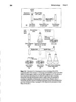
Figure 6.19 Magnetoresisuve head operation
This multilayer sandwich arrangement is shown in Figure 6.19. The copper
write coil is shown at the top of this figure, and the MR read element is further down
the stack .
• The write coil is copper. It is laid down
by
the same pbotolithography and
plating steps as described earlier. However, now that it only has to perform the
write function, it ismuch thinner and easier to make than a head that must per-
form both the write and the read functions. The head requires fewer copper
coils, material layers, photolithography steps, and tolerance controls. This in
itself also leads to fewer complications in manufacturing and a better yield .
•The read element is nickel/iron and is laid down
by
sputtering. The NiFe alloy
exhibits a change in resistance as it passes over a magnetic field: this is the MR
effect. Shielding layers protect the element from other magnetic fields. One
shield is shown to the left of the MR sensor in Figure 6.20. The other shield is
actually merged with and part of the write coil. Further developments in the
material itself lead to the "giant MR effect." The pickup sensor is a multilayer
sandwich with a thin metal interlayer able to respond to even smaller mag-
netic fields.
As before, an inductive write element writes bits of information to magnen-
calIybiased regions within radially concentric tracks on the disc.When it isnecessary
to read the data back, the MR sensor is used rather than another inductive head. The
MR
sensor picks up this magnetic transition (or flux reversal) between bits, causing
the magnetization in the MR sensor to rotate.The read current isindicated inFigure620.
This rotation is detected as a resistance change by a precision amplifier, which then
produces a stronger signal to the disc drive output.
Inductive head
P~MR~hidd 2
MRcontacl
MRshiddl
lnducuve wrilt head
P7b,,,",
6.5 Management of Technology
255
Figure 6.20 Magnetoresistive head design
6.5 MANAGEMENT OF TECHNOLOGY
6.5.1 The Culture and History of the Computer Industry
The evolution of the electronic computer over the past six decades from a rare,
highly specialized item to a commodity has repeatedly reshaped the computer
industry (Stern, 1980;Bell, 1984).Table 6.2 shows some of the main milestones.
As one example, in 1953,having assembled transistors with other discrete com-
ponents, IBM decided to make a prototype and investigate the market for the 1YJ>e650
magnetic drum calculator. The 1YPe650's computing power was roughly equivalent to
a modem VCR and rented for $3,250per month, equivalent to $20,000in today's dol-
lars. IBM was then a large, slow-moving corporation with an appropriately conserva-
tive marketing group. The market for a commercial computer was estimated to be
small. But when the stalwart
Type
650 was finally withdrawn from the market in 1962,
several thousand had been sold. In this situation, IBM successfully crossed the chasm
described in Chapter 2 and created a unique and viable product: one of the world's first
mass-produced computers. By 1964,IBM launched the /360 series of machines, which
incorporated a wide range of possible products for awide variety of users. But it should
be stressed that at that time, the users of this computing world were the academic!
scientific community on the one hand and commerciallbusiness corporations on the
other. The average consumer and the average family certainly did not sit down in the
evening to write a letter on a computer, let alone read e-mail or surf the Web.
For this average consumer, the most significant breakthrough in computing did
not occur until the development of the microprocessor. Throughout the 1960s,
I.Writecunenl
Shteld2JPl
Shield I
Track width
Inductive
wriledemenl
R<:eorJin~n1('dillm
Magneuzuuou
TABLE
6.2 Some of the Milestones in the Development of the Electronic Computer
Decade Prototype Comments Figure(s)
194"
ENlAC Vacuum tubes of the electronic numerical Eckert andMauch1y
integrator and calculator
EDVAC Stored programs
of
the eLectronic discrete von Neumann
variable automatic computer
EDSAC
Stored programs of the electronic delay
Wilkes
storage automatic calculator
Transistor Semiconductors:evenlUaUyreplace Shockley,Brattain,
vacuum tubes and Bardeen
1950s
UNIVAC1 Universal automatic computer launched as Eckert and Mauchly
the first commercial electronic computer
650 and 701 Frrst systems launched by IBM
IBM
IC Combined functions on one chip
Kilby
1_
f360Series Frrst"farnily"ofmachinesofwidely
IBM
different capability and cost
PDPS Minicomputer sold for
<S20,OOO
DEC
CDC 6600
First supercomputer
C"y
!'n"
4004 First microprocessor
Hoff and Intel
Apple II Erst personal computer JobsandWozoiak
Internet Interconnectivity for the academic community
DARPA
19'"
IBM PC Best-selling personal computer + multimedia
IBM, Intel, and
Microsoft
The Web
Networked computing
CERNfBerners-Lee
1990.
Compaq
The PC as a commodity
Pfeiffer
Mosaic
Interconnectiviry for mass consumption
NCSA/Andreesen
(Netscape)
Java "Write once run anywhere" computing
Son
PDAs Handheld devices and network computers (NC)
Palm Pilot
-2000 Wireless Merging of computing/wireless/infonnation
Nokia and Motorola
appliances into wide array of consumer
products (sometimes called a "POllt"PC"phase)
advances in
Ie
design and fabrication methods set the stage for the first micro-
processor, the 4004 (shown at the beginning of Chapter 5), developed at Intel by a
group led by Ted Hoff. It was based on two key innovations:
• All logic was on one chip.
• The device was programmable by software.
The microprocessor made possible a huge middle ground of general-purpose
machines, most notably the personal computer (PC) and high-performance work-
stations. The distinction between these categories is now blurred, particularly as pow-
erful networked
Pes
rival the functionality of professional workstations.
By 1977, Jobs and Wozniak huilt and sold the Apple II as a commercial
product, and by 1981, the IBM-PC was announced, using the Intel 80 x 86 micro-
Computer Manufacturing Chap. 6
256
6.5 Management of Technology
257
processor. Although its PC was a tremendous success, IBM did not fully capitalize
on its brilliant new product. It was not appreciated at the time that modest computing
power on everyone's desk would be more attractive than greater computing power cen-
tralized on mainframes. As a result, two historic choices were made by IBM:
• It subcontracted the PC operating system to Microsoft .
•It
subcontracted the
Ie
fabrication to InteL
Many professional and amateur analysts now look back and criticize these two
choices, which, at first glance, appear to have been shortsighted. At the time, how-
ever, these subcontracting arrangements were considered sensible because they min-
imized research and development (R&D) investment in areas that were not IBM
strengths. And as time has gone on, there has in fact been an increasing trend in all
industries toward subcontracting. While it is easy to look back and criticize IBM for
not getting the maximum benefit from the first PC, on balance, the decision made at
the time was consistent with today's conventional wisdom-namely, to focus on
one's core strengths and main markets while outsourcing all other operations. Today,
for most of the well-known, brand-name computer companies (e.g., Compaq, Dell,
Hewlett-Packard,) the trend is toward more outsourcing to companies that provide
specialized manufacturing services (e.g., Solectron, Flextronics, SCI systems).
Nevertheless the commercial significance of the computer operating system
and main microprocessor is now obvious to anyone who uses what bas become
known as the "Wlntel'' de facto standard. The significance of keeping pace with IC
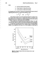
technology is illustrated in Figure 6.21, which shows the tremendous increases in IC
complexity and power over the last three decades.
lE+8
1E-t-7
1E+6
Transistors
per chip
1E+5
80286
8086
lE+4
lE+3
1970 1975 1980 1985 1990 1995 2000 2005
Yo ar
Flpre 6.21 The transistor count in the central processing unit (CPU) from 1970
and projected to 2005.
Pentium<ilProprocessor
Pennumverocessor
'DEC1264
~ PPC620
PPC604
~ vrPC601
Spare
MIPS4400
DEC21064
258
Computer Manufacturing Chap. 6
6.5.2
The Present
From a management of technology point of view, the computer industry is about
coping-or failing to cope-with change. With new technologies and applications
emerging all the time, the dust barely settles after one revolution before another is
well under way.In this environment of constant change, staying in business requires
mastery of all aspects of the technology management process. from research and
development to design, manufacturing, and marketing. The recent history and some
of the present situations in the computer industry illustrate how difficult this can be,
even for some top performers.
• IBM and DEC suffered during the early 19908 because they were large con-
servative organizations, overcommitted to a mainframe philosophy .
• Apple lost market share throughout the 1990s. Analysts and economic
observers cite many possible reasons, which usually include a closed proprietary
operating system that deters third party software development (see the com-
ments on VHS versus Betamax in the preface), low supplies of the best-priced
products at critical selling times during the year, and a neglect of design for
assembly manufacturing (DFAJM). Apple's future still remains uncertain at the
time of this writing despite the captivating aesthetic designs of recent products.
In contrast, Dell, Compaq, and Gateway have boosted profitability and cap-
tured the market lead by (a) redesigning their products to aggressively cut costs and
(b) improving their manufacturing productivity with DFAIM. To hold on to their
present lead, such companies have also introduced major innovations in their supply
chams.
Dell in particular has become famous for the "direct sales" model. Capitalizing
on a well-organized Website, the company builds each PC to order. This has the ben-
efit of eliminating the middleman-the computer dealer. This direct sales approach
delays commitment on the final product configuration until the last possible
moment. In this way, unnecessary inventories do not build up, and subcomponents
can be selectively stocked based on the most popular configurations. Other examples
of this strategy are the European assembly plants in the Netherlands, which build
computers for the multilingual European market. Again, by delaying commitment to
the very last minute, a company does not get stuck with too many keyboards or soft-
ware applications in the wrong language.
Dell also minimizes working capital and maximizes the return on it by using a
technique known as a negative cash conversion cycle. This means that a consumer
pays Dell for the assembled computer and FedEx shipping costs long before Dell
pays its subsuppliers for the parts. This has a double benefit given that the price of
subcomponents is constantly tumbling. Curry and Kenney (1999) describe the loss-
of-value dynamics of critical subcomponents in the PC industry. They report that
many of Dell's competitors continue to lose market share because they are unable
to manage time as effectively and consequently buy subsupplies at higher prices than
they can later package and sell them for. By delaying payment to their subsuppliers
until the PC is sold to the consumer, Dell effectively buys the subcomponents at the
last-minute (actually postminute) market price.
6.5 Management of Technology 259
6.5.3 The Future
In summary, the versatility and the power of PCs have now made them the work-
horses of the information age.All professionals now depend on their desktop, laptop,
or handheld computers for word processing, e-mailing, and access to Web-based
information and services.
Despite this range of possibilities, fewer and fewer of us are in any way over-
whelmed by computers. Or if so, we try not to let it show! The real news is that com-
puters are not just smaller and faster; they are also a lot cheaper. The basic computer,
especially in the form of the PC, is a common commodity, well on its way up the
market adoption curve in Chapter 2. The PC is not quite on a par with pork bellies
on the Chicago Stock Exchange, but it is getting there, The "sub-$l,OOOmachine" has
become the center of today's consumer market, and price performance has become
the main focus for the manufacturers. Handheld, networked wireless devices are
more recent additions to the marketplace. These take advantage of the wireless
application protocol (WAP), which allows PDAs to easily access the Internet.
In the eyes of many analysts, these are heralding a "post-PC age" of convenient
devices that boot up directly to specific applications, rather than have the user
stumble through the icons on a PC desktop just to get to the Internet?
As a result, multimedia and communications technologies are merging with
computers, and industry boundaries are dissolving. Newly formed business
alliances-sometimes called "virtual corporations"-are clashing for technical and
market leadership. These new alliances usually consist of two or more from the fol-
lowing list of constituents:
•PC and PDA makers of Silicon Valley and other high-tech regions
• Chip makers, with Intel being the obvious giant
• Operating system and software developers, dominated by Microsoft
•Telephone companies and network suppliers
• Television and cable TV companies
• Hollywood studios, backed up by special effects companies
At first glance, it is difficult to tell which type of alliance will come out on top,
and what the computer of the future will/ook like and what it will do. But based on
the history of the IC, the microprocessor, the PCB, and especially the computer itself,
it is certain that rapid dramatic changes are in store.
Consider, for example, the following thought exercise. Choose the most likely
scenario for the next several years:
Option 1:
"WebTV" will offer even more powerful set-top boxes and smart keyboards
for "interactivation." Television will have so much more interactivity and
"For example, Alan Kessler, president of acorn's Palm Computing, is quoted as follows in
u.s.
News ana World Report, December 13, 1999, p. 52:The new mantra is "give them [consumers] just what
they need when they need it" rather than respond to the "old" consumer demand of: "Give me more
memory. Give me more power. Give me more complex software."
280
Computer Manufacturing Chap. 6
bidirectional communication that the standard desktop PC will be made
redundant.
Option 2: The web-based PC will become a high-resolution "information furnace"
(a buzzword courtesy of Avram Miller of Intel). Voiceover modems,
video-telephone links, live concerts
by
musicians, MP3, and high-quality
video images will make TV obsolete.
Opdon 3: Neither TVs nor
PCS
will diminish in popularity. Rather, consumers will
continue to have high-quality TV entertainment in the living room and
high-quality information processing in the home office.
Option 4:
The PC in its current instantiation will disappear, and its central micro-
processor will essentially be absorbed internally as the central informa-
tion motor into all such information appliances. Norman (1998) and other
observers make the analogy that a stand-alone electric motor was once, in
the 1920s, a consumer product in and of itself. It was advertised in the
Sears catalog as something "every home should have," connectable to
washing machines, refrigerators, and hair dryers. Now, in the passing of
time, the electric motor is of course just as important, but it is not seen as
an external stand-alone device; rather it is buried deep inside consumer
appliances and taken for granted. So this may be the future of today's Pc.
It will be "reduced to a powerful microprocessor" and just be the central
"information motor" for TVs, PDAs, communication devices, and infor-
mation appliances. This idea is now a recurring theme in the popular mag-
azines of the computer industry, such as Wired, PC Computing, and Red
Herring (1998).
6.5.4
Philosophy
Archaeologists and historians traditionally view the growth of civilization in terms
of the predominant technology of particular eras. Chapter 1 mentioned the Stone
Age, the Bronze Age, the Iron Age, and the Steel Age of the industrial revolution.
Observers of the history of computing also try to document the chronological "eras"
that summarize the rise of the computer from the early mechanical computers, to the
vacuum tube era, to the Ie, and to the microprocessor (e.g., see Stem, 1980; Bell,
1984; Patterson and Hennessy, 1996a; Economist, 1996).
Partially based on these other writings,the present text hypothesizes that the his-
tory and anticipated future of commercial computers may be divided into four distinct
phases. Note that these commercial developments could not have been launched
without some truly revolutionary scientific research discoveries, such as the transistor
and the planar transistor in the period beginning in 1947.Usually,the commercial devel-
opment phase is5 to 10years behind the scientific discovery phase and prototype use by
the academic community. This is certainly true of the World Wide Web (see Berners-
Lee, 1989).Actually, this particular gap is 25 years if today's "dot-com-fever" is meas-
ured from the beginning of the DARPAnet and itsuse in the academic community.
6.5.4.1 The Iron Age (1953 to 1980)
The reign of the mainframe computer.
6.5 Management of Technology
2.'
6.5.4.2 The Desktop PeAge (1981 to 1991)
The age of stand-alone desktop personal computers, augmented by CD-ROM.
6.5.4.3 The World Wide Web Age (1992 to 2001)
The age of multimedia applications carried to a global communication level well
beyond the limits of an individual user's desktop PC. It involved the merging of
the World Wide Web, CD-ROM, TV, telephone, workstation, and wireless com-
munications technology.
6.5.4.4 The Integrated Man-Machine Age (2002 to 2020 and
Beyond)
For 1999, The Economist (1999) states that U.S. consumers purchased 16.9 million
PCs-17% mure than in
1998 raisiug
household penetration to 52%. However, the
same and other observers indicate a possible reduction over the next few years due
to several factors: (a) overcapacity; (b) reducing demand for upgrades-many users
have "powerful enough" machines; and (c) the rise of PDAs, smart cellular phones,
and networked computers (see Red Herring, 1998).
Obviously the PC "ruled" in the desktop age (1981-1991) and was the key
workhorse or platform for the World Wide Web age (1992-2001). However, in the
new age of man-machine devices, distinctions and interfaces between human beings
and their communication devices are now blurred. As aresult, the monolithic PC solu-
tion to life will fade, just as the monolithic mainframe faded.
Today's wireless-handheld combination of a cellular phone and PDA is only
the beginning of a new age of man-machine devices. Wearable computers are already
established devices in advanced applications. Weiss (1999) provides a popular
review. Akella and associates (1992), Smailagic and Siewiorek (1993), and Finger and
colleagues (1996) provide more scientific details. Extrapolating from these existing
prototypes, how might the following list of technical developments influence future
products?
• Assuming success with the developments in x-ray lithography and so forth
described in Chapter 5, it is reasonable to assume that more than a billion tran-
sistors will be packaged on a logic chip in the near future, opening up a whole
new range of computing capabilities at a scale never before possible.
•With billion-transistor chips, all the technologies of the World Wide Web age
might well be packaged into a voice-activated, hearing-aid-sized device that
can be worn at all times.
• Beyond 2020, with advances in engineering biologically compatible materials,
it might well be possible to embed such a tiny but powerful electronic device
in the lining of the scalp; a subcutaneous radio modem would be a realistic
option.
Several decades ago, the philosopher and physicist Heisenberg was one of the
first people to futurize about such possibilities. He used the following metaphor to
conjecture about our future. Snails, crabs, and similar creatures can exist and live
262
Computer Manufacturing Chap. 6
without their protective helmets (shells) but not very effectively. Is it possible,
Heisenberg then asked, that human beings are living beneath our full potential? If
we were equipped with a kind of "information helmet" -c-using these technologies of
the integrated man-machine
age-then
we would dramatically increase
information
access and expand the effectiveness of our lives.
When these ideas are discussed in a lecture, many people squirm at the thought
of embedding a microprocessor and a radio modem under their skin. People seem to
accept and welcome external devices like hearing aids and pacemakers, but it does
seem a threatening "jump" to go to internal devices. However, other philosophers
have postulated that humankind could have discovered the wheel more quickly if
our thinking patterns were not blocked off by observing the rest of nature where no
wheel-like devices are found.
Perhaps we are also blocking the thought of internally embedded electronic
devices for the same reason-namely, that they do not appear anywhere else in
nature. If we can look beyond this threatening jump-to devices that will improve
our personal communication networks, our ability to compensate for injury, and our
general health and immunity support functions-then perhaps the Ie and the micro-
processor will indeed reach out to an even wider range of tasks.
6.6 GLOSSARY
6.6.1 Ball Grid Array (BGA)
Development of individual SMT components, where the connections are made
underneath the chip instead of on the perimeter. The term ball grid refers to the small
balls of solder used to make the connections.
6.6.2
Bus
The bus connects the microprocessor, disc drive controller, memory, input/output
ports, and other parts of the system.
6.6.3
Central Processing Unit (CPU)
The main arithmetic and control units plus working memory.
6.6.4 Compiler
A program that translates from high-level problem-oriented computer languages to
machine-oriented instructions.
6.6.5 Design for Assembly and Manufacturing (DFA/DFMI
Strategy of lowering cost by aiming at lowering assembly time and reducing the
number of subcomponents. Design for assembly involves three key ideas: reducing
the number of subcomponents, increasing their quality, and simplifying the assembly
operations between subcomponents.
6.6 Glossary
263
6.6.6 Flip Chip Technology (FCTI
Extension of SMT/BGA that offers even greater packing density. The IC is turned
over and placed face down on the board before creating the circuit connections.
6.6.7 Head Gimbal Assembly (HGAI
An assembly of a read/write head on an arm. This holds the head in place over the
rotating disc.
6.6.8 Head Stack Assembly IHSA)
An assembly of the HGAs (above), the actuator coil, and a flexible printed circuit
cable.The HSA also includes a read/write preamplifier, a head selection circuit, and
other miscellaneous parts.
6.6.9 Interconnection
The process of mechanically joining devices together to complete an electrical cir-
cuit. Also, the conductive path needed to connect one circuit element to another or
to the rest of the circuit system.Interconnections may be leads,soldered joints, wires,
or another joining system.
6.6.10 Known Good Die IKGDI
A semiconductor die that has been tested and is known to function properly
according to specifications.
6.6.11 Lands
Small solder lands/regions of the PCB that provide for the connection of individual
ICs and components.
6.6.12 Multichip Modules (MCM)
A device containing two or more packaged fCs mounted and interconnected on a
substrate.
6.6.13 Pin-in-Hole (PIHI
A PCB assembly method that involves inserting the leads of components into holes
in the board, clipping, and soldering the leads into place.
6.6.14 Printed Circuit Board (PCB)
Also called a printed wiring board (PWB), this is a rigid insulating substrate with
conductors etched on the external and/or internal layers.PCBs include single-sided,
double-sided, and multilayer boards. A raw "starter board" is a PCB without com-
ponents attached to it.
.84
Computer Manufacturing Chap. 6
6.6.15 Printed Circuit Board Assembly (or Printed Wiring
Assembly IPWA]
A PCB with all components mounted and interconnected on it.
6.6.18 Sliders
The heads, or magnetic coils, of the read/write unit of the disc.
6.8.17 Substrate
On a PCB., the base material that provides a supporting surface for etching circuit
patterns, as well as attaching components.
6.6.18 Surface Mount Technology (SMT)
The process of attaching components directly to the surface of a PCB. Increasingly,
SMf
is
replacing the older pin-in-hole method.
6.6.19 Tape Automated Bonding
A process in which precisely etched leads (supported on a flexible tape or plastic car-
rier) are interconnected to the chip or a substrate
by
a heated pressure head. This
process simultaneously creates a bond for all leads at once.
6.6.20 Test Coupon
A preset pattern of copper pads and/or holes for testing during manufacture.
6.6.21 Tracks
Parts of the PCB that provide the interconnections among components and variouslCs.
6.6.22 Wave Soldering
Teclutique of collectively soldering the components to the printed circuit board by passing
the board over a standing wave of molten solder that fixes the leads of the components.
6.7 REFERENCES
AClS Technical Overview. 1999. ACIS geometric modeler. Programming manual. Boulder,
CO: Spatial Technology Inc.
Akella,J.,A. Dutoit, and D. P. Seiwiorek. 1992.A prototyping case study. In Proceedings of the
3Td IEEE InternationalWorkshop on Rapid System Prototyping. Research Triangle Park, NC:
IEEE.
Allen. W., D. Rosenthal, and K. Fiduk. 1991. The MCC CAD framework methodology man-
agement system. In Proceedings of the 28th ACMlIEEE Design Automation Conference,
694-698.
Amir B.,H. Balakrishnan,S. Seshan, and R. Katz.1995.EfficientTCP over networks with wire-
less links. In Proceedings of the Fifth Workshop on Hot Topics in Operating Systems. Orcas
Island,WA
6.7 References
265
Andrade,A. D.1996.Aceeptability of fabricated circuits. In Printed circuits handbook, 4th ed.,
edited by C. F. Coombs J"L, 35.3-35.41. New York: McGraw-Hill.
Barnes, T., D. Harrison, A. Newton, and R. Spickelmier. 1992. Electronic CAD frameworks.
Kluwer Academic Publishers.
Bell, C. G. 1984. The mini and micro industries. IEEE Computer 17 (10): 14 30.
Berners-Lee, T. 1989.lnfonnation management: A proposal. CERN Internal Proposal, March.
Bohr, M.I998. Silicon trends and limits for advanced microprocessors. Communications of the
ACM 41 (3):80-87.
Brodersen, R. W.I997. The network computer and its future. In Proceedings of the IEEE Inter-
national Solid-State Circuits Conference. San Francisco, CA.
Buntein,A.,A. C Long, S. Narayanaswamy, et aI.I995. The lnfoPad user interface. In
COMPeON
'95, 159-162.
Cho, T., G. Chien, F. Brianti, and P. R. Gray.
1996.A
power-optimized CMOS baseband channel
filter and
ADC
for cordless ••applications.
VI W
Cirruil Confl'rl'lIre nigl',~r
96, June
Clark, R.H.1985.Handbook of printed circuit manufacturing. New York: VanNostrand Reinhold.
Cole, R. E. 1999. Managing quality fads: How American business learned to play the quality
game. New York and Oxford: Oxford University Press.
Curry, I, and M. Kenney. 1999. Beating the clock: Corporate responses to rapid changes in the
PC industry. California Management Review 42 (1): &-36.
Duffek, E. F. 1996. Plating. In Printed circuits handbook, 4th ed, edited by C F. Coombs Jr.,
19.1-19.55. New York: McGraw-Hili.
Economist. 1994.A survey of the computer industry, 17 (suppl.): 1-22.
Economist. 1999. A bad business, July, 53-54.
Finger, S.,I Stivoric, and CAmon, et aI.1996. Reflection on a concurrent design methodology:
A case study in wearable computer design. Computer Aided Design 28 (5): 393-404.
Fulton, R. F._
19R7.
A framework for innovation. Computers in Mechanical Engineering, March.
Gilleo, K., T. Cinque, and A. Silva. 1996.Flip chip 1,2,3: Bump bond and fill. Clrcuits Assembty;
June,32-34.
Green, H. D. 1996. Multichip modules. In Printed circuits handbook, 4th ed., edited by C F.
Coombs Jr., 6.1-6.31. New York: McGraw-Hili.
Groover, M. P. 1996. Fundamentals of modem manufacturing, 87&-906. Prentice-Hall.
Guerra, M., M. Potkonjak, and 1. Rabaey.I994. System-level design guidance using algorithm
properties. In VLSI Signal Processing VII, 73 82: IEEE Press.
Gupta, R., et. al. 1989. An object-oriented VLSI CAD framework: A case study in rapid pro-
totyping.IEEE Computer 22 (5): 28-37.
Guy, E. T. 1992. An introduction to the CAD framework initiative. In Electro 1992 Conference
Record. Boston, MA.
Inside Read-Rite Corporation. 1993. (Informational brochure. Milpitas, CA: Read-Rite Cor-
poration.
Keller, K. H. 1984. An electronic circuit
CAD
framework. Ph.D Thesis, Department of Elec-
trical Engineering and Computer Science, University of California, Berkeley.
Lao,A.,1 Reason, and D. Messenchmitt.I994.Asynchronous video coding for wireless trans-
port./EEE Workshop on Mobile Computing, December, Santa Cruz, CA.
Le, M, T., F. Burghardt, S. Seshan, and J. Rabaey. 1995. InfoNet: The networking infrastructure
of InfoPad. In Proceedings of Compean '95.
286
Computer Manufacturing Chap. 6
Leicht, H. W.1995. Reflew soldering and repair of BOAs. In 10th European Microelectronics
Conference, 508-520.
Long, A.
c,
S. Narayanaswamy, A. Burstein, R. Han, K. Lutz, B. Richards, S. Sheng, R. W.
Brodersen, and 1. Rabaey. 1995. A prototype user interface for a mobile multimedia terminal.
In
Proceedings of the
1995
Computer Human Interface Conference.
Mead,
c.,
and L.
Conway. 1980.
Inrroducrion to VLSI systems. Reading,
MA:
Addison
Wesley.
Messner, G. 1996. Electronic packaging and interconnectivity. In
Printed circuits handbook,
4th ed. edited by C. F. Coombs Jr., 1.3-1.22. New York: McGraw-Hill.
Mitt,M .•G. Murakami, T. Kumakura, and N. Okabe.1995.Advanced interconnect and low cost
micro stud BGAIn The 1995 JEEF.lCPMT Electronics Manufacturing Symposium, 428-521.
Nakahara,H.l996.1)'pes of printed wiring boards. In Printed circuits handbook, 4th ed.,edited
by C. F. Coombs Jr.,3.1-3.14. New York: McGraw-HilI.
Narayanaswamy, S., S. Seshan, E. Brewer, R. Brodersen, F. Burghardt, A. Burstein, Y-C,
Chang,A. Fox,I Gilbert, R. Han,R. Katz,A. C. Long,O. Messerschmitt,1. Rabaey.1996.Appli~
cation and network support for InfoPad. IEEE Personal Communications Magazine, March.
Norman, D. A. 1998. The invisible computer. Cambridge, MA; MIT Press.
Palmer, PI, D. I Williams, and CHughes. 1996. Assembly and packaging of conventional elec-
tronics. Process Group Technical Report No. 96/13.1. England; Loughborough University.
Patterson, D. A., and I L. Hennessy. 1996a. Computer architecture: A quantitative approach.
San Francisco, CA: Morgan Kaufmann Publishers.
Patterson, D. A., and I L. Hennessy. 19%b. Computer organization and design: The hardware!
software interface. San Francisco,
CA
Morgan Kaufmann Publishers.
Rabaey, J., L. Guerra, and R. Mehra. 1995. Design guidance in the power dimension. Paper
presented at the International Conference on Acoustic, Speech and Signal Processing.
Read-Rite Corporation. 1997.Thchnicalliterature available from 345 Los Caches St., Milpitas, CA.
Red Herring. 1998. The post-PC world, December,50-66.
Sarma S. E., S. Schofield, 1.A. Stori, 1. MacFarlane and P. K. Wright. 1996. Rapid product real-
ization from detail design. Computer-Aided Design 28, (5); 383-392.
Sheldahl Technical Staff. 1996. In Printed circuits handbook, 4th ed. edited by C. F. Coombs Jr.,
40.1-40.31. New York: McGraw-Hili.
Sheng,
s.,
R.Allmon,L. Lynn, I. O'Donnell, K. Stone, and R. W. Brodersen. 1994. A monolithic
CMOS radio system for wideband COMA communications. In Wireless '94 Conference Pro-
ceedings. Calgary, Canada.
Smailagic,A., and D. P Siewiorek. 1993.A case study in embedded-system design: The VuMan
2 Wearable Computer. IEEE Design and Test of Computers, September, 56 67.
Stafford, 1. W. 1996. Semiconductor packaging technology. In Printed circuits handbook, 4th
ed., edited by C. R Coombs Jr., 2.1-2.16. New York: McGraw-Hill.
Stem, N. 1980. Who invented the first electronic judicial computer? Annals of the History of
Computing
2 (4): 375-376.
Sturges, R. H., and P. K. Wright. 1989. A quantification of dexterity. Journal of Robotics and
Computer Aided Manufacturing 6 (1): 3-14.
Wang,
F c.,
B. Richards, and P. K. Wright. 1996. A multidisciplinary concurrent design envi-
ronment for consumer electronic product design. Concurrent Engineering: Research and
Applications 4 (4); 347-359.
Wang,
F c.,
P. K. Wright, B. A. Barsky, and D. C. H. Yang. 1999. Approximately arc-length
parametrized C3 quintic interpolatory splines. Transactions of the AS ME, Journal of Mechan-
ical DUign121 (3): 430-439.
6.8 Case Study on Computer Manufacturing
267
Weiss, P. 1999. Smart outfit.
Science News
156 (21): 330-332.
Yeh, C. P.1992.An integrated information framework for multidisciplinary PWB design. Ph.D
Thesis, Georgia Institute of Technology.
Yeh, C. P., R. E. Fulton,and R. S. Peak. 1991. A prototype information integration framework for
electronic packaging. Paper presented at the ASME 1991 Wmter Annual Meeting.Atlanta, GA.
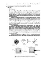
6.8 CASE STUDY ON COMPUTER MANUFACTURING'
6.8.1
Overview
This case study presents the product development process of the InfoPad shown in
Figure 6.22. The InfoPad is a portable, wireless computer aimed at an approximate
selling price of $300. It provides text and graphics, pen input, limited speech input,
Fipn (j.2Z
The InfoPad~a wireless "information appliance" (see
<www.ua.bwu.be keJey.edu».
>zhe InfoPad
Wlill
a large collaborative project, and particu.lar acknowledgmenu are made to the
following colleagues: Professor Robert Brodersen,Professor Jan Rabaey, Dr. Frank Wang, Brian Richards,
Susan MeYers, and many students at the Berkeley Wireless Research Center.
268
Computer Manufacturing Chap. 6
audio output, and full-motion color video. In a restricted classroom or home envi-
ronment it can be used as a mobile communication device and a sketch pad
(Brodersen, 1997). Twenty prototypes were produced as evaluation kits for mar-
keting purposes and user testing in a college classroom.
6.8.2 Goals of the Case Study
Some key points that may be learned in the case study include the following:
• Designing and fabricating a complex system like the InfoPad require collabo-
ration between many engineering disciplines. Specifically, most consumer elec-
tronic products are electromechanical systems. They consist of mechanical
components such as structures, enclosures, and mechanisms, combined with
electrical components such as printed circuit boards, power supplies, wires
(harnesses), and switches. In spite of the advancements within each field-
namely, the electrical CAD tools (BCAD) shown in Figure 5.9 and the
mechanical CAD tools (MCAD) shown in Table 3.2-a gap still exists today
for good communication between BCAD and MCAD. The cartoon of Figure 6.23
captures this struggle .
• An environment called the domain unified computer aided design environ-
ment (DUCADE) has thus been developed to address this need. It is a con-
current engineering system for ECADIMCAD. The links from (a) conceptual
design to (b) detail design to (c) fabrication are smooth and deterministic, cre-
ating a fast link from the initial design to a fabricated product. This integration
improves product quality and time-to-market.
Flpre 6.13 DUCADE has the
goal of reducing
the
wall
between ECAD and
MCAD.
6.8 Case Study on Computer Manufacturing
269
• A specific focus is on constraint resolution between electrical and mechanical
issues.A central virtual-white-board environment is created to share and com-
municate coupled design issues during the design process.
• Various electrical and mechanical subsystems can be designed for modularity
and reused in successive design generations. This further accelerates the design
to production time.
6.8.3
Conceptual Design
The conceptual design phase of the InfoPad involved a functional requirement tree.
Figure 6.24 is a global overview of the product design space. Design constraints were
specified for each functional requirement as hard (cannot be changed) or soft (can
be changed) constraints. For example, a hard design constraint was the desired
weight of less than 2 pounds, under the functional requirement of "portable."
6.8.4
Concurrent Detailed Design Using DUCADE
The detailed designs for the InfoPad subsystems were conducted by various design
teams. These included the pad group, the wireless communication (radios) group, the
multimedia network group, the user interface group, and the mechanical design group.
Each group used its own domain design tools to perform specific design tasks.
However, at certain critical junctures. predetermined design data within each
team's domain were shared with other teams in a collaborative way. For example,
Figure 6.25 illustrates the collaboration between the "pad group" and "mechanical
design group." The PCB of the pad was designed using the Racal PCB layout tools,
and the InfoPad casing was designed using the MSCI ARIES mechanical design
package.
The domain unified computer aided design environment (DUCADE) then
provided concurrent access to all the design tools of each team. Importantly, at crit-
ical junctures.
it
specifically provided online checking and verification of the design
issues that were predetermined as being coupled between design teams.
Commercial CAD packages that were encapsulated in the DUCADE system
included four MCAD packages and two ECAD packages: MSC/ARIES,
4
AutoCAD,
5
ProEngineer,6 ACIS,
7
Finesse,
8
and RacaWisula.
9
ARIES and AutoCADI
ProEngineer were primarily used for mechanical component design and mechanical
analyses such as interference and thermal analyses. ACIS was the solid modeling
kernel and package for solid modeling. Racal/ Visula was the major electrical design
tool for PCB layout design.
4MSCIARIESTMis a trademark of MacNeal Schwendler Corporation.
5AlltocADTh< is a trademark of Autodesk Inc.
6ProEngineerTl.t is a trademark of Parametric
Technology
Corporation.
7ACISn< is a trademark of Spatial
Technology
Inc.
8Finesse™ is a trademark of Harris EDA Inc.
~calIV'ISUalTM is a trademark of Racal-Redac.
270
Computer Manufacturing Chap. 6
Flcure 6.24 Design
architecture of the InfoPad system.
Readers who are interested in the electrical system design can refer to the litera-
ture for radios in wireless communication development (Sheng et aI., 1994;Cho et
aI., 1996), mobile multimedia networking and applications (I.e et
al,
1995; Amir et
el.,
1995; Narayanaswamy at al., 1996), video aad graphic transport (Lao at al., 1994), user
Proxim/Plessy radics
XLink radio controls
antenna
-Plastic (ABS) casing
- Color display module
- Ribbons/connectors
-Screws
- 9V battery set (Sx9V)
Mechanical
subsystem
-Enclosure
-Structure
-Conneceors
- Power supply
RFsubsystem
-TI-ansmission
-Receiving
-Controt
Text/graphics
subsvstem
Video subsystem
Audio ~uhsvslem
Handwritingreoog
XIIserverf
pen/audio servers!
videoserverl
GPIB
LCDdillplays
Central control
-CPU
-ROMIRAM
Detail design mappin
Medtev networl
ARMsubsystern
System evaluation
InfoPad multimedia portable terminal
Applications]
. Constraint specification
Multimedia access
'wireless communication
Portable terminal
InfoPad system design
System specification
Backbone network
Protocols
I
Base stationIRadioIPeninoul
I
Audio 110
Graphics
Video
BW=1-2Mbps
Power
Sire
Weight
COOl
System embodiment
Backbone network
-Infrastructure
-Protccols
6.8 Case Study on Computer Manufacturing
27'
Flpre 6.25 Detailed design of mechanical casing and PCB.
interface applications (Long et al.,1995),and design tools and framework (Guerra et aI.,
1994;Rabaey et el., 1995;Wang et al., 1996).Table 6.3 summarizes the implementation.
6.8.5
Coupled Design Constraints
Figure 6.26 shows some of the coupling constraints that occurred between the mechan-
ical and electrical domains. For clarity, only one arrow is shown for the coupling rela-
tionship between the locations/orientations of the electronic components and the
enclosure's shape. This coupling relationship usually required iterative design tasks
with close communication between mechanical and electrical designers to achieve
compact packaging. Because the lnfoPad was designed to be alow-power device,many
constraints focused on the compact packaging of ICs,devices, and displays.
6.8.6 Coupling Constraints Originating in the Mechanical
Domain
IC , J
Several constraints originated on the "mechanical side" and had to be accommo-
dated on the "electrical side."They are given the symbol
em:>
e
They were as follows:
• Given the 8 x 11 x 1 format-deliberately chosen to mimic the familiar engi-
neers' clipboard the available space inside the terminal enclosure was lim-
ited. It thus impacted the available area as well as the height for the display and
the PCBs and their components.
TABLE
6.3 Major Electrical Subsystems and Components of InfoPad
Majorsubsystenu
Functionality Major parts
Source/part No
PAL
Commercial part/ATV 2500L
EPROM Commercial part/AM27COlO
Arm subsystem Central control Octal buffer Commercial partlHCfS74
SRAM CommercialpartffC551001 BFL-85
ARM60 Commercial partlGPS-P60ARMPR
ARM interface chip Custom designed and fabricated
Plesseydownlink
Commercial part/GEC.DE6003
Proxirn uplink
Commercial partlRDA.l00f200
Radio subsystem
Wifeless
Xilinix
Commercial partlXC-4008
communications
RXchip Custom designed and fabricated
TXSRAM
Commercial partffC551001 BFL·85
Antenna
f
x 2) Commercial partlEXC-VHF 902
SMJEXC-UHF 2400
Text/graphics LCD Commercial part/Sharp LM64k83
display
Color video LCD
Commercial partlSharp LQ4RAOI
display
Text/graphics chip set Custom designed and fabricated
Multimedia
Multimedia
110
(x 5)
subsystem Color video chip set l.'ustomdesignedandfabricated
(x 5)
Audio control chip set Custom designed and fabricated
(x5)
Gazelle pen board
Commercial part
110
subsystem
Codec
Commercial partlMCl45554
Speaker Commercial part
Power subsystem Power supply
9VbatteryX 5 Commercial pan
• Given the standard mechanical/UI features on the terminal casing-for
example, the window for the LCD display on the top case, the access window
fOTthe battery set-again, the shapes, dimensions, and positions of the PCBs
and their components were limited to certain values.
• Given the fact that the casing needed mechanical supporting structures. venti-
lation grids, and antenna positioning relative to the user's body, certain restric-
tions on placement of ICs were inevitable.
To display these fOTthe electrical designers, DUCADE provided a simple "lay-
ered" view of the (em> •.,) mechanical constraints. This was because the electrical
design teams were familiar with 2.5~D layout tools (rather than 3-D tools) for ICs
and PCBs. Figure 6.27 shows the internal layout of the bottom casing. The maximum
computer Manufacturing Chap. 6
272
Flture 6.26
Coupling mechanical/electrical design constraints,
Figun- 6.27 Layout of the mechanical constraints,
273
("Mechanical'"
design
constraints
Ergonomic
constraints
Aesthetic
(geometric)
constraints
I
Thermal
constraints
Impact
(stress)
constraints
Weight
Material
Enclosure
~
Enclosure
~
Mech.comp
\Ioc. and orienl
~
~
~
~~-
SomeD •••.•gn
Parameten
Electrical
design
constraints
Power
constraints
Electromagnetic
constraints
Proximity
constraints
.Routing area
Etec.comp.
loc. and orienl.
Shielding
Power
~
~