Bearing Design in Machinery Episode 3 Part 4 pps
Bạn đang xem bản rút gọn của tài liệu. Xem và tải ngay bản đầy đủ của tài liệu tại đây (450.2 KB, 15 trang )
the bearings. The first type of an adjustable bearing arrangement is shown in Fig
13-8. In this arrangement, the apex points, A, are outside the two bearings. As
shown in Fig. 13-8, tightening a threaded ring on the housing side does the
adjustment. In this way, the bearing cup (outer ring) is shifted in the axial
direction and, thus, the clearance in the two bearings can be adjusted. In this
arrangement, a temperature rise will always result in a tighter bearing clearance.
In the bearing arrangement of Figs. 13-8a and 13-8b, if the bearings are
preloaded when the machine is cold, the temperature rise results in a higher
bearing preload and rolling contact stresses. If some bearing clearance is left after
the adjustment, the clearance will be reduced due to the thermal expansion. As
discussed earlier, the advantage of this arrangement type is that it can be designed
to allow a final adjustment during operation, after the machine has reached a
steady thermal equilibrium.
13.11.1.2 Apex points between the two bearings
This arrangement is often referred to as O arrangement, because the lines in the
direction normal to the contact lines, intersecting at point S, form an O shape.
These lines are the directions of the forces acting on the rolling element. In
angular contact ball bearings (see Fig. 13-9d), these lines form the contact angle.
In general, arrangement of apex points between the two bearings (O
arrangement) is preferred whenever a strong axial guidance is required. This
means that the shaft is supported more rigidly than the adjustable arrangement
with apex points outside the bearings. The direction of the rolling-elements
reaction force resists better any rotational vibrations of the shaft around an axis
perpendicular to the shaft centerline.
The effect of a temperature rise may be different in the second arrangement
type, which is shown in Figs. 13-9a, 13-9b, and 13-9c, where the apex points are
between the bearings. As shown in these figures, tightening a nut on the shaft side
does the adjustment. The bearing cone (inner ring) is shifted in the axial direction,
and the clearance in the two bearings is adjusted.
During operation, the temperature rise increases the shaft length and at the
same time increases the diameter of the inner ring (cone). In the second
arrangement type (Figs. 13-9), a thermal expansion of the shaft length has a
loosening effect on the two bearings; however, at the same time, the thermal
expansion of the cone diameter has a tightening effect. The combined effect
depends on the ratio of the shaft length to the cone diameter. The combined
thermal effects can be determined by the location of the apex points. This
arrangement can be divided into three cases:
1. For a short distance between the two bearings, the roller cone apex
points overlap, as shown in Fig. 13-9a. In this case, the thermal
expansion of the cone (inner ring) diameter has a larger effect than
Copyright 2003 by Marcel Dekker, Inc. All Rights Reserved.
the axial expansion of the shaft. The combined effect is that the thermal
expansion increases the preload. This combined effect should be
considered and the bearings should be adjusted with a reduced preload
in comparison to the desired preload during operation.
2. The two apex points coincide, as shown in Fig. 13-9b. In this case, the
axial and the radial thermal expansions compensate each other without
any significant thermal effect on the clearance.
3. The distance between the bearings is large and the roller cone apices do
not overlap, as shown in Fig. 13-9c. In this case, the cone (inner ring)
thermal expansion is less than that of the shaft. In turn, the combined
thermal effect is to increase the clearances of the two bearings (or
reduce the preload). This should be considered, and the bearings are
usually adjusted tighter with more preload in comparison to the desired
preload during operation.
The selection of the adjustment arrangement type depends on several
factors. The second type, where the roller cone apices are between the bearings,
has more rigidity to keep the shaft centerline in place. In addition, it can be
designed so that the thermal expansion is compensated. The first type, where the
roller cone apices are outside the bearings, is often selected in order to allow a
fine adjustment during operation. This is possible to do only if the threaded ring
(or other adjustment design) is accessible for adjustment during the operation of
the machine.
13.11.2 Inner and Outer Ring Fits
The inner or outer ring that is adjusted should move freely by means of a slightly
loose fit, while the other ring is mounted with a tight fit. As with other rolling
bearings, the inner ring (cone) should always be mounted with a tight fit when the
cone rotates. Similarly, the outer ring (cup) should be mounted with a tight fit
when it rotates. For a rotating shaft, this requirement usually favors the first type
of adjustable bearing arrangement, where the apex points are outside the two
bearings. However, the second type is often used for rotating shafts as well.
If the housing rotates, as in a nondriven car wheel, the cup is tightly fitted.
If the bearing is subjected to severe loads, shocks, or frequent direction reversals,
such as in construction equipment, both cup and cone must be tightly fitted.
For high-speed applications, such as turbines and high-speed machine
tools, an adjustable arrangement of angular contact ball bearings is preferred,
because tapered rolling bearings have higher friction. In a similar way to the
intersection of cone apices, in angular contact bearings the arrangement type is
determined by the intersection of the lines normal to the angular bearing contact
lines.
Copyright 2003 by Marcel Dekker, Inc. All Rights Reserved.
Manufactured pairs of angular contact ball bearings or tapered bearings are
available. The bearings are paired in a first-or second-type arrangement. Angular
contact ball bearings of these designs are accurately finished and can be selected
with a low axial clearance, a zero clearance, or a light preload.
13.11.3 Designs for Reduction of Thermal E¡ects
on Bearings Preload
It is important that the bearings in an adjustable arrangement will operate with the
desired precise preload force. However, the operating temperature can fluctuate
resulting in a variable preload force. Excessive preload can reduce the fatigue life
of the bearing, and if the preload is reduced, the bearings’ stiffness may be too
low. Engineers are always looking for new designs for mitigating the thermal
effect, so that a precise preload will be sustained in the bearings.
It is possible to design a preloaded bearing arrangement where springs
provide the thrust force. The spring force is not as sensitive to the thermal
elongation in comparison to the rigid shaft in the common adjustable bearing
arrangement. The advantage is that the spring force is constant, and the preload
force does not increase by the temperature rise during bearing operation.
Examples of designs where springs provide the preload force are shown in
Sec. 13.12.
Additional example for reducing the effect of the temperature on the level
of the preload force is by using two spacer sleeves between the two bearings for
the outer and inner rings of the adjustable arrangement. The two spacer sleeves
have only a small contact area with the rings and housing. The spacer for the
inner rings has an air clearance with the shaft, and the spacer for the outer rings
has an air clearance with the housing. It results that the two long spacer sleeves
are nearly thermally isolated, and have approximately equal temperature during
operation. In this way, the axial elongation of the two long spacer sleeves is equal
without any significant effect on the preload. An example of a design where two
long spacer sleeves are used for a NC Lathe spindle bearing arrangement is
shown in Sec. 13.12.
13.11.4 Machine Tool Spindles
The two most important requirements for machine tool spindle bearings are
(a) high precision (very low bearing run-out)
(b) high rigidity (very low elastic deformation under load).
High precision spindle bearings are manufactured with very low tolerances,
which are tested for very small radial and axial run-out. In addition, the bearing
seats must have similar precision, and very good surface finish. The requirement
Copyright 2003 by Marcel Dekker, Inc. All Rights Reserved.
of high stiffness can be achieved by using relatively large bearings that are
precisely preloaded. For precision machining, the cutting forces should result in
very small elastic deformation. Therefore, the system of spindle and bearings
must be rigid. For this purpose, machine tool designs entail large diameter spindle
and large bearings, in comparison to other machines with similar forces. More-
over, to ensure rigidity of the system, the bearings must be preloaded, in order to
minimize the elastic deformation at the contacts of rolling elements and races.
The requirement for high stiffness results in large bearings relative to other
machines with similar forces; therefore, the fatigue life is usually not a problem in
machine tool spindle bearings. Spindle bearings usually do not fail by fatigue, but
can wear out, and it is important to have clean lubricant to reduce wear.
In most cases, machine tools are fitted with angular contact ball bearings to
support the high thrust load. The requirement for high axial stiffness under heavy
thrust cutting forces is achieved in many cases by arrangement of two or more
angular contact ball bearings in tandem arrangement (see Sec. 13.10.1). The
bearings are preloaded by adjustable arrangement, and care must be taken to
ensure that the preload will remain constant and will not vary due to variable
bearing temperature. Examples of bearing arrangements for machine tool
spindles are presented in Sec. 13.12.
13.12 EXAMPLES OF BEARING ARRANGEMENTS
IN MACHINERY
13.12.1 Vertical-Pump Motor (Fig. 13-10a)
Design data
Power: 160 kW
Speed: 3000 RPM
Thrust force: 14 kN (Total of weight of rotor and impeller, pump thrust
force and spring force).
Tolerances
cylindrical roller bearing shaft m5; housing M6
deep grove ball bearing: shaft k5; housing H6
angular contact bearing: shaft k5; housing E8
Lubrication: Grease lubrication with time period of 1000 hours between
lubrications.
Design: This is a locating=floating bearing arrangement. The two bearings
at the top form the locating side, whereas the lower cylindrical roller
bearing is a floating bearing. In the locating top bearings, preload is
Copyright 2003 by Marcel Dekker, Inc. All Rights Reserved.
the required rigidity, two angular contact ball bearings in tandem arrangement are
fitted at each side.
For mitigating the effect of the temperature rise on the preload level, the
design includes two spacer sleeves of approximately equal temperature between
the two bearings for axial support of the outer and inner rings of the adjustable
arrangement (see Sec. 13.11.3).
Design data
Power:27kW
speed: 9000 RPM
Lubrication: The bearings are greased and sealed for the bearing life, and
35% of cavity is filled. Sealing is via labyrinth seals.
Tolerances: High precision spindle bearings are used. The bearings have
tight fit on the shaft seat (shaft seat tolerance þ5=À5 mm), and sliding fit
on the housing seats, (housing seat tolerance þ 2=þ10 mm).
13.12.3 Bore Grinding Spindle (Fig. 13-10c)
Design data
Power: 1.3 kW
Speed: 16,000 RPM
Lubrication: The bearings are greased and sealed for the bearing life.
Sealing is by labyrinth seals.
Design: High rigidity is required. Angular contact ball bearings are used of
15
contact angle for high radial stiffness, and each side has a tandem
arrangement for axial stiffness. Bearings have adjustable arrangement
and are lightly preloaded by a coil spring.
FIG. 13-10b NC-lathe main spindle. (From FAG, 1998, with permission of FAG OEM
and Handel AG).
Copyright 2003 by Marcel Dekker, Inc. All Rights Reserved.
Lubrication: Oil injection lubrication. A well designed, non-contact
labyrinth seal prevents oil leaks and protects the bearings from any
penetration of cutting fluid and metal chips.
Design: The bearings have adjustable arrangement and lightly preloaded by
springs.
13.12.5 Gearbox (Fig 13-10e)
Design data
Power: 135 kW
Speed: 1000 RPM
Tolerances: shaft m5, housing H6
Lubrication: Splash oil from the gears. Shaft seals are fitted at the shaft
openings.
13.12.6 Worm Gear Transmission (Fig. 13-10f)
Design data
Power: 3.7 kW
Speed: 1500 RPM
FIG. 13-10e Gearbox (from FAG, 1998, with permission of FAG OEM and Handel
AG).
Copyright 2003 by Marcel Dekker, Inc. All Rights Reserved.
13.12.8 Guide Roll for Paper Mill (Fig. 13-10h)
Design Data
Speed: 750 RPM
Roll weight:80kN
Paper pull force:9kN
Bearing load: 44.5 N
Bearing temperature: 105
C
Tolerances: housing G7, inner ring fitted to a tapered shaft
Lubrication: oil circulation
Sealing: double noncontact seal, as shown in Fig 13-10h. The double
noncontact seals prevent oil from leaking out.
Design: Special bearings durable to the high operation temperature of the
dryer are required. Bearing manufacturers offer high-temperature bear-
FIG. 13-10g Passenger car differential gear (with permission of FAG OEM and
Handel AG).
Copyright 2003 by Marcel Dekker, Inc. All Rights Reserved.
13.12.10 Support R oller of a Rotary Kiln
(Fig. 13-10j)
Design Data
Radial load: 1200 kN
Thrust load: 700 kN
Speed: 5 RPM
Tolerances
Shaft n6
Housing H7
Lubrication and Sealing: Grease lubrication with lithium soap base
grease. At the roller side, the bearings are sealed with felt strips and
grease packed labyrinths.
Design: The bearings are under very high load, and are exposed to a severe
dusty environment. Lithium soap base grease is used for bearing
lubrication and for sealing. These rollers support a large rotary kiln,
which is used in cement manufacturing. Self-aligning spherical roller
bearings are used. The two bearings are mounted in a floating arrange-
FIG. 13-10i Centrifugal pump (from FAG, 1998, with permission of FAG OEM and
Handel AG).
Copyright 2003 by Marcel Dekker, Inc. All Rights Reserved.
ment (to allow axial adjustment to the kiln). The bearings are mounted
into split plummer block housings with a common base.
The grease is fed directly into the bearing through a grease valve
and a hole in the outer rings. The grease valve restricts the grease flow
and protects the bearing from overfilling. The bearings have double seal
of felt strip and grease packed labyrinth. A second grease valve feeds
grease directly into the labyrinth seal and prevents penetration of any
contamination into the bearings.
The support roller shown in this figure has diameter of 1.6 m and
width of 0.8 m. The speed is low, N ¼5 RPM and the load on one
bearing is high, Fr ¼1200 kN. These rollers support the rotary kiln for
cement production. The kiln dimensions are 150 m long and 4.4 m
diameter. The supports are spaced at 30 m intervals.
13.12.11 Crane Pillar Mounting (Fig. 13-10k)
Design Data
Thrust load: 6200 kN
Radial force: 2800 kN
Speed: 1 RPM
Tolerances: Shaft j6, housing K7
Lubrication and Sealing: Oil bath lubrication with rollers fully immersed
in oil.
FIG. 13-10k Crane pillar mounting (from FAG, 1998, with permission).
Copyright 2003 by Marcel Dekker, Inc. All Rights Reserved.
Sealing: Noncontact labyrinth seal as shown in Fig 13-10k. The crane
usually operates in severe dust environment. The labyrinth is full of oil,
to prevent any penetration of dust from the environment into the bearing.
13.13 SELECTION OF OIL VERSUS GREASE
Greases and oils are widely used for lubrication of rolling-element bearings. In
this section, the considerations for selection of oil versus grease are discussed. In
addition to considerations directly related to bearing performance, selection
depends on economic considerations as well as the ease of maintenance and
effective sealing of the bearing.
Whenever possible, greases are preferred by engineers because they are
easier to use and involve lower cost. For example, grease lubrication is widely
selected for light-and-medium-duty industrial applications, in order to reduce the
cost of maintenance. However, at high speeds, considerable amount of heat is
generated in the bearings, and greases usually deteriorate at elevated tempera-
tures. In addition, liquid oils improve the heat transfer from the bearing.
Empirical criterion that is widely used by engineers for the selection of oil
versus grease is the DN value, which is the product of rolling bearing bore (equal
to shaft diameter) in mm and shaft speed in RPM. Rolling bearings operating at
DN value above 0.2 million usually require liquid oil, although there are special
high-temperature greases that can operate above this limit. Below this limit, both
greases and oils can be used. This is an approximate criterion, which considers
only the bearing speed for medium loads. In fact, the load, friction coefficient,
and heat sources outside the bearing also affect the bearing temperature.
In addition to the DN value, the product of speed and load is used to
determine whether the bearing operates under light or heavy-duty conditions.
This product is proportional to the bearing temperature rise (see estimation of the
temperature rise in Sec. 13.3). The bearing operation temperature must be much
lower than the temperature limit specified for the grease.
For low-speed rolling bearings, grease is the most widely used lubricant,
because it has several advantages and the maintenance cost is lower. In
comparison to oil, grease does not leak out easily through the seals. Prevention
of leakage is essential in certain industries such as food, pharmaceuticals and
textiles. Tight contact seals on the shafts are undesirable because they introduce
additional friction and wear. The advantage of grease is that it can be used in
bearing housings with noncontact labyrinth seals. The grease does not leak out, as
oil would, and it seals the bearing from abrasive dust particles and a corrosive
environment. Rolling bearings are sensitive to penetration of dust, which causes
severe erosion, and the bearings must be properly sealed. Section 13.23 presents
various types of contact and noncontact seals.
Copyright 2003 by Marcel Dekker, Inc. All Rights Reserved.
Contact seals are often referred to as tight seals or rubbing seals. They are
tightly fitted on the shaft and are used mostly for oil lubrication. They introduce
additional energy losses due to high friction between the seal and the rotating
shaft, which raises the bearing temperature. Tightly fitted seals are also undesir-
able because they wear out and require frequent replacements; they should be
avoided wherever possible. Moreover, the shaft wears out due to friction with the
seal. In high-speed machines, expensive mechanical seals are often used to
replace the regular contact seals. An important advantage of grease lubrication is
that noncontact labyrinth seals of low friction and wear can be used effectively. In
certain applications, unique designs of noncontact seals are used successfully for
oil lubrication (see Sec. 13.12.11).
Grease is particularly effective where the shaft is not horizontal and oils
leak easily through the seals. For grease, a relatively simple noncontact labyrinth
seal with a small clearance is adequate in most applications.
A very thin layer of grease can be applied on the races to reduce the friction
resistance. In such cases, the friction is lower than for oil sump lubrication.
Another important advantage of grease is the low cost of maintenance in
comparison to oil. Oil requires extra expense to refill and maintain oil levels.
In addition, oil can be lost due to leakage, and expensive frequent inspections of
oil levels must be conducted in order to prevent machine failure. In comparison,
in grease lubrication, there is no need to maintain oil levels, and the addition of
lubricant is less frequent. In most cases, grease lubrication results in a lower cost
of maintenance.
Economic considerations favor grease lubrication. Oil lubrication systems
involve higher initial cost and the long-term bearing maintenance is also more
expensive. Therefore, oil is selected only where the selection can be justified based
on performance. Oil has several important performance advantages over grease.
1. Unlike grease, oil flows through the bearing and assists in heat transfer
from the bearing. This advantage is particularly important in applica-
tions of high speed and high temperature.
2. Continuous supply of oil is essential for the formation of an EHD fluid-
film. This is very important in high-speed machinery, such as gas
turbines.
3. Oil circulation through the bearing has an important function in
removing wear debris.
4. Liquid oil is much easier to handle via pumps and tubes, in comparison
to grease. In addition, oil is relatively simple to fill and drain; therefore
it should be selected particularly when frequent replacements of
lubricant are required.
5. In most applications, only a very thin lubrication layer is required. This
can be obtained by introducing an accurate slow flow rate of lubricant
Copyright 2003 by Marcel Dekker, Inc. All Rights Reserved.
(measured in drops per minute) into the bearing. Flow dividers
(described in Chapter 10) can be used for feeding at the desired flow
rate to each bearing. A precise amount of lubricant at a steady flow rate
can be supplied to the bearing and controlled only if the lubricant is oil;
this is not feasible with grease.
6. Oil can provide lubrication to all the parts of a machine. An example is
a gearbox, where the same oil lubricates the gears as well as the
bearings.
As this discussion indicates, grease can be selected for light- and medium-
duty applications, whereas oil should be selected for heavy-duty applications in
which sufficient flow rates of liquid oil are essential for removing the heat from
the bearing and for the formation of a fluid film.
13.14 GREASE LUBRICATION
The compositions and properties of various greases are discussed in Chapter 3.
Greases are suspensions of mineral or synthetic oil in soaps, such as sodium,
calcium, aluminum, lithium, and barium soaps, as well as other thickeners, such
as silica and treated clays. The thickener acts as a sponge that contains and slowly
releases small quantities of oil. When the rolling elements roll over the grease, the
thickener structure breaks down gradually. Minute quantities of oil release and
form a thin lubrication layer on the races and rolling-element surfaces. The
lubrication layer is very thin and cannot generate a proper elastohydrodynamic
film for separation of the rolling contacts, but it is effective in reducing friction
and wear. In addition, the oil layer is too thin to play a role in cooling the bearing
or in removing wear debris.
13.14.1 Design of Bearing Housings for Grease
Lubrication
The design of the housing and grease supply depends mostly on the temperature,
bearing size, load, and speed as well as the environment. The following is a
survey of the most common designs.
13.14.1.1 Bearings Packed and Sealed for Life
If the bearing operating temperature is low and its speed and load are not high, the
life of the grease can equal or exceed the bearing life. In such cases, using a
bearing packed with grease and sealed for life would reduce significantly the
maintenance cost. Sealed-for-life small bearings are commonly used under light-
duty conditions. Sealed-for-life bearings are also used for occasional operation
(not for 24 hours a day), such as in cars, domestic appliances, and pumps for
Copyright 2003 by Marcel Dekker, Inc. All Rights Reserved.
occasional use. Examples are small electric motors for domestic appliances,
bearings supporting the drum of a washing machine, and many bearings in
passenger cars, such as water pump bearings.
The grease life is sensitive to a temperature rise, and sealed-for-life bearings
are not used in machines having a heat source that can raise the bearing
temperature. In some applications that involve a moderate temperature rise,
such as small electric motors, sealed-for-life bearings with high-temperature
grease are used successfully. We have to keep in mind that the life of sealed ball
bearings is limited to the lower of bearing life and lubricant life. A method for
estimating grease life is presented in Sec. 13.15.
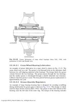
Fig. 13-11 presents an example of the front wheel of a front-wheel-drive
car. A double-row angular contact ball bearing is used. Certain cars use angular
contact ball bearings or tapered roller bearings that are adjusted. The bearing is
packed with grease and sealed on both sides for the life of the bearing.
FIG. 13-11 Sealed-for-life bearing in the front wheel of a front-wheel-drive car (from
FAG, 1988, with permission).
Copyright 2003 by Marcel Dekker, Inc. All Rights Reserved.
13.14.1.2 Housing Without Feeding Fittings
For industrial machines that operate for many hours, if the bearings operate at low
temperature under light-to-medium duty, the original grease in the housing can
last one to two years or even longer. In such cases, the grease can be replaced by
new grease only during machine overhauls and the housing is not provided with
grease-feeding fittings.
Housing without feeding fittings are used only if there is no heat source
from any process outside the bearing and if the bearing operating temperature due
to friction is low. This can be applied to light- and medium-duty bearings, namely,
where the load and speed are not very high.
The advantage of elimination of any grease fittings is that it prevents
overfilling of grease in the housing. The old grease is replaced by new grease only
during overhauls, and this can be done manually without using grease guns. Only
one-third to one-half the volume of the housing is filled with grease for regular
applications. However, to minimize friction in small machines, only a very thin
layer of grease is applied on the bearing surfaces, particularly if the drive motor is
small and has low power.
Overfilling of grease in the bearing housing results in a high resistance to
the motion of the rolling elements and grease overheating, as well as early
breakdown of the grease (the grease is overworked). Therefore, the use of high-
pressure guns for feeding grease into the housing of rolling bearings is undesir-
able, particularly for large bearings, because it packs too much grease into the
housing and causes bearing overheating. Moreover, feeding under high pressure
always results in grease loss.
During the assembly and periodic relubrication, it is very important to keep
the bearing and lubricant completely clean from dust or even from old grease.
Although less than half the volume of the housing is filled for regular applica-
tions, if the bearing is exposed to a severe environment of dust or moisture, the
bearing should be fully packed to seal the bearing and prevent its contamination.
Grease-feeding fittings are provided for frequent topping-up of grease. In many
cases, additional grease fittings feed grease directly to the labyrinth seals (see Sec.
13.12). Fully packed bearings are used only for low- and medium-speed bearings,
where the extra friction power loss is not significant.
13.14.1.3 Housings with Feeding Fittings
The common bearing design includes fittings for grease topping-up (adding
grease between replacements by grease gun). Although it is desirable not to
overfill the housing with grease, this is difficult to avoid. Low-cost maintenance is
an important consideration, and in most cases the new grease replaces the old by
pushing it out with grease guns. Experience indicates that small, light-duty
Copyright 2003 by Marcel Dekker, Inc. All Rights Reserved.
bearings can operate successfully even when overfilled with grease. Overfilling
initially generates extra resistance, but the extra grease is lost over time through
the labyrinth seals. The housing is often designed with an outlet hole at the lower
side of the housing and noncontact labyrinth seals. The temperature of the
overfilled grease rises; after running a few hours (depending on bearing size and
grease consistency), the surplus grease escapes through the hole and labyrinth
seals. Low-consistency grease is used for this purpose.
If the bearing is exposed to an environment of dust, overfilling prevents
contamination of the bearing. Frequent topping-up of grease ensures overfilling,
particularly near the seals. The grease fittings must be completely clean before
adding grease.
For small and medium-size bearings, it is possible to avoid overfilling and
at the same time simplify the grease replacement. This is done via a simple
housing design that allows one to force the old grease out completely with the
new grease. The design includes a large-diameter drain outlet with a plug, in the
side opposite the inlet grease fitting and at the lower side of the housing. This way
the grease must pass through the bearing. In order to avoid overfilling, the
replacement procedure is as follows: The outlet plug is removed; the shaft is
rotating while the new grease is pumped into the housing. The old grease is
worked out so that it is easier to replace. The new grease is pumped until it starts
to come out of the drain. The shaft rotates for about half an hour to allow the
surplus grease to drain out before locking the outlet.
This method is not applicable to large bearings because the pressure of the
grease gun is not sufficient to remove all the old grease through the outlet. Also,
the bearing might be overfilled, resulting in overheating during operation.
Therefore, in large bearings, the grease is replaced manually during overhauls.
In addition, large bearings require topping-up of grease at certain intervals,
determined according to the temperature and operating conditions. It is important
to avoid overfilling during relubrication. The addition of grease is done with
grease guns, and it is important to design the housing and fittings to prevent
overfilling. These designs involve higher cost and can be justified only for larger
bearings.
13.14.2 Design Examples of Bearing Housings
It is important to ensure by appropriate design that during topping-up of grease,
the new grease (fed by grease guns) will pass as much as possible through the
bearings. The grease is supplied as close as possible to the bearings and
discharged through the bearing into the space on the opposite side. In this way,
the new grease must pass through the bearing, and the new grease will replace the
old grease as much as possible.
Copyright 2003 by Marcel Dekker, Inc. All Rights Reserved.