Database Modeling & Design Fourth Edition- P27 ppt
Bạn đang xem bản rút gọn của tài liệu. Xem và tải ngay bản đầy đủ của tài liệu tại đây (172.79 KB, 5 trang )
6.2 The Design of Normalized Tables: A Simple Example 117
4. proj_no -> proj_name, proj_start_date, proj_end_date
5. dept_no -> dept_name, mgr_id
6. mgr_id -> dept_no
Our objective is to design a relational database schema that is nor-
malized to at least 3NF and, if possible, minimize the number of tables
required. Our approach is to apply the definition of third normal form
(3NF) in Section 6.1.4 to the FDs given above, and create tables that sat-
isfy the definition.
If we try to put FDs 1 through 6 into a single table with the compos-
ite candidate key (and primary key) (emp_id, start_date), we violate the
3NF definition, because FDs 2 through 6 involve left sides of FDs that are
not superkeys. Consequently, we need to separate 1 from the rest of the
FDs. If we then try to combine 2 through 6, we have many transitivities.
Intuitively, we know that 2, 3, 4, and 5 must be separated into different
tables because of transitive dependencies. We then must decide whether
5 and 6 can be combined without loss of 3NF; this can be done because
mgr_id and dept_no are mutually dependent and both attributes are
Figure 6.5 ER diagram for employee database
emp-id
emp-name
phone-no
office-no
Employee
N
N
N
1
1
1
1
has
works-in
manages
works-on
Emp-history
job-title
proj-end-date
proj-start-date
proj-name
proj-no
mgr-id
dept-name
dept-no
start-date
end-date
1
Department
Project
Teorey.book Page 117 Saturday, July 16, 2005 12:57 PM
118 CHAPTER 6 Normalization
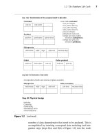
superkeys in a combined table. Thus, we can define the following tables
by appropriate projections from 1 through 6.
emp_hist: emp_id, start_date -> job_title, end_date
employee: emp_id -> emp_name, phone_no, proj_no, dept_no
phone: phone_no -> office_no
project: proj_no -> proj_name, proj_start_date, proj_end_date
department: dept_no -> dept_name, mgr_id
mgr_id -> dept_no
This solution, which is BCNF as well as 3NF, maintains all the origi-
nal FDs. It is also a minimum set of normalized tables. In Section 6.4, we
will look at a formal method of determining a minimum set that we can
apply to much more complex situations.
Alternative designs may involve splitting tables into partitions for
volatile (frequently updated) and passive (rarely updated) data, consoli-
dating tables to get better query performance, or duplicating data in dif-
ferent tables to get better query performance without losing integrity. In
summary, the measures we use to assess the trade-offs in our design are:
• Query performance (time)
• Update performance (time)
• Storage performance (space)
• Integrity (avoidance of delete anomalies)
6.3 Normalization of Candidate Tables Derived from
ER Diagrams
Normalization of candidate tables [step II(d) in the database life cycle] is
accomplished by analyzing the FDs associated with those tables: explicit
FDs from the database requirements analysis (Section 6.2), FDs derived
from the ER diagram, and FDs derived from intuition.
Primary FDs represent the dependencies among the data elements that
are keys of entities, that is, the interentity dependencies. Secondary FDs, on
the other hand, represent dependencies among data elements that com-
prise a single entity, that is, the intraentity dependencies. Typically, pri-
mary FDs are derived from the ER diagram, and secondary FDs are
obtained explicitly from the requirements analysis. If the ER constructs do
Teorey.book Page 118 Saturday, July 16, 2005 12:57 PM
6.3 Normalization of Candidate Tables Derived from ER Diagrams 119
not include nonkey attributes used in secondary FDs, the data require-
ments specification or data dictionary must be consulted. Table 6.1 shows
the types of primary FDs derivable from each type of ER construct.
Each candidate table will typically have several primary and second-
ary FDs uniquely associated with it that determine the current degree of
normalization of the table. Any of the well-known techniques for
increasing the degree of normalization can be applied to each table to
the desired degree stated in the requirements specification. Integrity is
maintained by requiring the normalized table schema to include all data
dependencies existing in the candidate table schema.
Any table B that is subsumed by another table A can potentially be
eliminated. Table B is subsumed by another table A when all the
attributes in B are also contained in A, and all data dependencies in B
also occur in A. As a trivial case, any table containing only a composite
key and no nonkey attributes is automatically subsumed by any other
table containing the same key attributes, because the composite key is
the weakest form of data dependency. If, however, tables A and B repre-
sent the supertype and subtype cases, respectively, of entities defined by
the generalization abstraction, and A subsumes B because B has no
additional specific attributes, the designer must collect and analyze addi-
tional information to decide whether or not to eliminate B.
A table can also be subsumed by the construction of a join of two
other tables (a “join” table). When this occurs, the elimination of a sub-
Table 6.1 Primary FDs Derivable from ER Relationship Constructs
Degree Connectivity Primary FD
Binary or
one-to-one 2 ways: key(one side) -> key(one side)
Binary
one-to-many key(many side) -> key(one side)
Recursive
many-to-many none (composite key from both sides)
Ternary
one-to-one-to-one 3 ways: key(one), key(one) -> key(one)
one-to-one-to-many 2 ways: key(one), key(many) ->
key(one)
one-to-many-to-many 1 way: key(many), key(many) ->
key(one)
many-to-many-to-many none (composite key from all 3 sides)
Generalization
none none (secondary FD only)
Teorey.book Page 119 Saturday, July 16, 2005 12:57 PM
120 CHAPTER 6 Normalization
sumed table may result in the loss of retrieval efficiency, although stor-
age and update costs will tend to be decreased. This trade-off must be
further analyzed during physical design with regard to processing
requirements to determine whether elimination of the subsumed table is
reasonable.
To continue our example company personnel and project database,
we want to obtain the primary FDs by applying the rules in Table 6.1 to
each relationship in the ER diagram in Figure 4.3. The results are shown
in Table 6.2.
Next we want to determine the secondary FDs. Let us assume that
the dependencies in Table 6.3 are derived from the requirements specifi-
cation and intuition.
Normalization of the candidate tables is accomplished next. In Table
6.4 we bring together the primary and secondary FDs that apply to each
candidate table. We note that for each table except employee, all
attributes are functionally dependent on the primary key (denoted by
the left side of the FDs) and are thus BCNF. In the case of table
employee, we note that spouse_id determines emp_id and emp_id is
the primary key; thus spouse_id can be shown to be a superkey (see
Superkey Rule 2 in Section 6.4). Therefore, employee is found to be
BCNF.
Table 6.2 Primary FDs Derived from the ER Diagram in Figure 4.3
dept_no -> div_no in Department from relationship “contains”
emp_id -> dept_no in Employee from relationship “has”
div_no -> emp_id in Division from relationship “is-headed-by”
dept_no -> emp_id from binary relationship “is-managed-by”
emp_id -> desktop_no from binary relationship “has-allocated”
desktop_no -> emp_no from binary relationship “has-allocated”
emp_id -> spouse_id from binary recursive relationship
“is-married-to”
spouse_id -> emp_id from binary recursive relationship
“is-married-to”
emp_id, loc_name -> project_name from ternary relationship “assigned-to”
Teorey.book Page 120 Saturday, July 16, 2005 12:57 PM
6.3 Normalization of Candidate Tables Derived from ER Diagrams 121
In general, we observe that candidate tables, like the ones shown in
Table 6.4, are fairly good indicators of the final schema and normally
require very little refinement to get to 3NF or BCNF. This observation is
important—good initial conceptual design usually results in tables that
are already normalized or are very close to being normalized, and thus
the normalization process is usually a simple task.
Table 6.3 Secondary FDs Derived from the Requirements Specification
div_no -> div_name, div_addr from entity Division
dept_no -> dept_name, dept_addr, mgr_id from entity Department
emp_id -> emp_name, emp_addr, office_no, phone_no from entity Employee
skill_type -> skill_descrip from entity Skill
project_name -> start_date, end_date, head_id from entity Project
loc_name -> loc_county, loc_state, zip from entity Location
mgr_id -> mgr_start_date, beeper_phone_no from entity Manager
assoc_name -> assoc_addr, phone_no, start_date from entity Prof-assoc
desktop_no -> computer_type, serial_no from entity Desktop
Table 6.4 Candidate Tables (and FDs) from ER Diagram Transformation
division
div_no -> div_name, div_addr
div_no -> emp_id
department
dept_no -> dept_name, dept_addr, mgr_id
dept_no -> div_no
dept_no -> emp_id
employee
emp_id -> emp_name, emp_addr, office_no, phone_no
emp_id -> dept_no
emp_id -> spouse_id
spouse_id -> emp_id
manager
mgr_id -> mgr_start_date, beeper_phone_no
secretary
none
engineer
emp_id -> desktop_no
Teorey.book Page 121 Saturday, July 16, 2005 12:57 PM