Database Modeling & Design Fourth Edition- P5 ppt
Bạn đang xem bản rút gọn của tài liệu. Xem và tải ngay bản đầy đủ của tài liệu tại đây (162.64 KB, 5 trang )
1.2 The Database Life Cycle 7
number of data dependencies that need to be analyzed. This is
accomplished by inserting conceptual data modeling and inte-
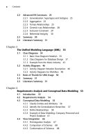
gration steps [steps II(a) and II(b) of Figure 1.2] into the tradi-
Figure 1.2 (continued)
Step III Physical design
Step II(c) Transformation of the conceptual model to SQL tables
Step II(d) Normalization of SQL tables
Customer
Product
prod-no prod-name qty-in-stock
cust-no
sales-name
sales-name
addr
addr
dept
dept
job-level
job-level job-level
vacation-days
vacation-days
Order-product
order-no
prod-no
Order
order-no sales-name cust-n
o
cust-name
. . .
Salesperson
Decomposition of tables and removal of update anomalies
Indexing
Clustering
Partitioning
Materialized views
Denormalization
Salesperson Sales-vacations
create table customer
(cust_no integer,
cust_name char(15),
cust_addr char(30),
sales_name char(15),
prod_no integer,
primary key (cust_no),
foreign key (sales_name)
references salesperson
foreign key (prod_no)
references product);
Teorey.book Page 7 Saturday, July 16, 2005 12:57 PM
8CHAPTER 1Introduction
tional relational design approach. The objective of these steps is
an accurate representation of reality. Data integrity is preserved
through normalization of the candidate tables created when the
conceptual data model is transformed into a relational model.
The purpose of physical design is to optimize performance as
closely as possible.
As part of the physical design, the global schema can some-
times be refined in limited ways to reflect processing (query and
transaction) requirements if there are obvious, large gains to be
made in efficiency. This is called denormalization. It consists of
selecting dominant processes on the basis of high frequency,
high volume, or explicit priority; defining simple extensions to
tables that will improve query performance; evaluating total cost
for query, update, and storage; and considering the side effects,
such as possible loss of integrity. This is particularly important
for Online Analytical Processing (OLAP) applications.
IV. Database implementation, monitoring, and modifica-
tion. Once the design is completed, the database can be created
through implementation of the formal schema using the data
definition language (DDL) of a DBMS. Then the data manipula-
tion language (DML) can be used to query and update the data-
base, as well as to set up indexes and establish constraints, such
as referential integrity. The language SQL contains both DDL
and DML constructs; for example, the create table command rep-
resents DDL, and the select command represents DML.
As the database begins operation, monitoring indicates
whether performance requirements are being met. If they are
not being satisfied, modifications should be made to improve
performance. Other modifications may be necessary when
requirements change or when the end users’ expectations
increase with good performance. Thus, the life cycle continues
with monitoring, redesign, and modifications. In the next two
chapters we look first at the basic data modeling concepts and
then—starting in Chapter 4—we apply these concepts to the
database design process.
1.3 Conceptual Data Modeling
Conceptual data modeling is the driving component of logical database
design. Let us take a look at how this component came about, and why
Teorey.book Page 8 Saturday, July 16, 2005 12:57 PM
1.3 Conceptual Data Modeling 9
it is important. Schema diagrams were formalized in the 1960s by
Charles Bachman. He used rectangles to denote record types and
directed arrows from one record type to another to denote a one-to-
many relationship among instances of records of the two types. The
entity-relationship (ER) approach for conceptual data modeling, one of
the two approaches emphasized in this book and described in detail in
Chapter 2, was first presented in 1976 by Peter Chen. The Chen form of
the ER model uses rectangles to specify entities, which are somewhat
analogous to records. It also uses diamond-shaped objects to represent
the various types of relationships, which are differentiated by numbers
or letters placed on the lines connecting the diamonds to the rectangles.
The Unified Modeling Language (UML) was introduced in 1997 by
Grady Booch and James Rumbaugh and has become a standard graphi-
cal language for specifying and documenting large-scale software sys-
tems. The data modeling component of UML (now UML-2) has a great
deal of similarity with the ER model and will be presented in detail in
Chapter 3. We will use both the ER model and UML to illustrate the data
modeling and logical database design examples throughout this book.
In conceptual data modeling, the overriding emphasis is on simplic-
ity and readability. The goal of conceptual schema design, where the ER
and UML approaches are most useful, is to capture real-world data
requirements in a simple and meaningful way that is understandable by
both the database designer and the end user. The end user is the person
responsible for accessing the database and executing queries and updates
through the use of DBMS software, and therefore has a vested interest in
the database design process.
The ER model has two levels of definition—one that is quite simple
and another that is considerably more complex. The simple level is the
one used by most current design tools. It is quite helpful to the database
designer who must communicate with end users about their data require-
ments. At this level you simply describe, in diagram form, the entities,
attributes, and relationships that occur in the system to be conceptual-
ized, using semantics that are definable in a data dictionary. Specialized
constructs, such as “weak” entities or mandatory/optional existence
notation, are also usually included in the simple form. But very little else
is included, to avoid cluttering up the ER diagram while the designer’s
and end user’s understandings of the model are being reconciled.
An example of a simple form of ER model using the Chen notation is
shown in Figure 1.3. In this example, we want to keep track of video-
tapes and customers in a video store. Videos and customers are repre-
sented as entities Video and Customer, and the relationship “rents”
Teorey.book Page 9 Saturday, July 16, 2005 12:57 PM
10 CHAPTER 1 Introduction
shows a many-to-many association between them. Both Video and Cus-
tomer entities have a few attributes that describe their characteristics,
and the relationship “rents” has an attribute due date that represents
the date that a particular video rented by a specific customer must be
returned.
From the database practitioner’s standpoint, the simple form of the
ER model (or UML) is the preferred form for both data modeling and end
user verification. It is easy to learn and applicable to a wide variety of
design problems that might be encountered in industry and small busi-
nesses. As we will demonstrate, the simple form can be easily translated
into SQL data definitions, and thus it has an immediate use as an aid for
database implementation.
The complex level of ER model definition includes concepts that go
well beyond the simple model. It includes concepts from the semantic
models of artificial intelligence and from competing conceptual data
models. Data modeling at this level helps the database designer capture
more semantics without having to resort to narrative explanations. It is
also useful to the database application programmer, because certain
integrity constraints defined in the ER model relate directly to code—
code that checks range limits on data values and null values, for exam-
ple. However, such detail in very large data model diagrams actually
detracts from end user understanding. Therefore, the simple level is
recommended as the basic communication tool for database design
verification.
Figure 1.3 A simple form of ER model using the Chen notation
due-datecust-id
cust-name
NN
Customer Video
video-id
copy-no
title
rents
Teorey.book Page 10 Saturday, July 16, 2005 12:57 PM
1.4 Summary 11
1.4 Summary
Knowledge of data modeling and database design techniques is impor-
tant for database practitioners and application developers. The database
life cycle shows the steps needed in a methodical approach to designing
a database,, from logical design, which is independent of the system
environment, to physical design, which is based on the details of the
database management system chosen to implement the database.
Among the variety of data modeling approaches, the ER and UML data
models are arguably the most popular ones in use today, due to their
simplicity and readability. A simple form of these models is used in most
design tools; it is easy to learn and to apply to a variety of industrial and
business applications. It is also a very useful tool for communicating
with the end user about the conceptual model and for verifying the
assumptions made in the modeling process. A more complex form, a
superset of the simple form, is useful for the more experienced designer
who wants to capture greater semantic detail in diagram form, while
avoiding having to write long and tedious narrative to explain certain
requirements and constraints.
1.5 Literature Summary
Much of the early data modeling work was done by Bachman [1969,
1972], Chen [1976], Senko et al. [1973], and others. Database design
textbooks that adhere to a significant portion of the relational database
life cycle described in this chapter are Teorey and Fry [1982], Muller
[1999], Stephens and Plew [2000], Simsion and Witt [2001], and Hernan-
dez and Getz [2003]. Temporal (time-varying) databases are defined and
discussed in Jensen and Snodgrass [1996] and Snodgrass [2000]. Other
well used approaches for conceptual data modeling include IDEF1X
[Bruce, 1992; IDEF1X, 2005] and the data modeling component of the
Zachmann Framework [Zachmann, 1987; Zachmann Institute for Frame-
work Advancement, 2005]. Schema evolution during development, a
frequently occurring problem, is addressed in Harriman, Hodgetts, and
Leo [2004].
Teorey.book Page 11 Saturday, July 16, 2005 12:57 PM