Database Modeling & Design Fourth Edition- P20 ppt
Bạn đang xem bản rút gọn của tài liệu. Xem và tải ngay bản đầy đủ của tài liệu tại đây (339.76 KB, 5 trang )
82 CHAPTER 4 Requirements Analysis and Conceptual Data Modeling
ships and process-to-data relationships. The conceptual data modeling
step (ER approach) involves the classification of entities and attributes
first, then the identification of generalization hierarchies and other
abstractions, and finally the definition of all relationships among enti-
ties. Relationships may be binary (the most common), ternary, and
higher-level n-ary. Data modeling of individual requirements typically
involves creating a different view for each end user’s requirements. Then
the designer must integrate those views into a global schema, so that the
entire database is pictured as an integrated whole. This helps to elimi-
nate needless redundancy—such elimination is particularly important in
logical design. Controlled redundancy can be created later, at the physi-
cal design level, to enhance database performance. Finally, an entity
cluster is a grouping of entities and their corresponding relationships
into a higher-level abstract object. Clustering promotes the simplicity
that is vital for fast end-user comprehension. In the next chapter we take
the global schema produced from the conceptual data modeling and
view integration steps, and we transform it into SQL tables. The SQL for-
mat is the end product of logical design, which is still independent of
any particular database management system.
4.7 Literature Summary
Conceptual data modeling is defined in Tsichritzis and Lochovsky
[1982], Brodie, Mylopoulos, and Schmidt [1984], Nijssen and Halpin
[1989], Batini, Ceri, and Navathe [1992]. Discussion of the requirements
data collection process can be found in Martin [1982], Teorey and Fry
[1982], and Yao [1985]. View integration has progressed from a represen-
tation tool [Smith and Smith, 1977] to heuristic algorithms [Batini, Len-
zerini, and Navathe, 1986; Elmasri and Navathe, 2003]. These algo-
rithms are typically interactive, allowing the database designer to make
decisions based on suggested alternative integration actions. A variety of
entity clustering models have been defined that provide a useful founda-
tion for the clustering technique shown here [Feldman and Miller, 1986;
Dittrich, Gotthard, and Lockemann, 1986; Teorey et al., 1989].
Teorey.book Page 82 Saturday, July 16, 2005 12:57 PM
83
5
Transforming the Conceptual
Data Model to SQL
his chapter focuses on the database life cycle step that is of particular
interest when designing relational databases: transformation of the
conceptual data model to candidate tables and their definition in SQL
[step II(c)]. There is a natural evolution from the ER and UML data mod-
els to a relational schema. The evolution is so natural, in fact, that it sup-
ports the contention that conceptual data modeling is an effective early
step in relational database development. This contention has been
proven to some extent by the widespread commercialization and use of
software design tools that support not only conceptual data modeling
but also the automatic conversion of these models to vendor-specific
SQL table definitions and integrity constraints.
In this chapter we assume the applications to be Online Transaction
Processing (OLTP). Note that Online Analytical Processing (OLAP) appli-
cations are the subject of Chapter 8.
5.1 Transformation Rules and SQL Constructs
Let’s first look at the ER and UML modeling constructs in detail to see
how the rules about transforming the conceptual data model to SQL
tables are defined and applied. Our example is drawn from the company
personnel and project conceptual schemas illustrated in Figure 4.3 (see
Chapter 4).
T
Teorey.book Page 83 Saturday, July 16, 2005 12:57 PM
84 CHAPTER 5 Transforming the Conceptual Data Model to SQL
The basic transformations can be described in terms of the three
types of tables they produce:
• SQL table with the same information content as the original entity
from which it is derived. This transformation always occurs for enti-
ties with binary relationships (associations) that are many-to-
many, one-to-many on the “one” (parent) side, or one-to-one on
either side; entities with binary recursive relationships that are
many-to-many; and entities with any ternary or higher-degree
relationship or a generalization hierarchy.
• SQL table with the embedded foreign key of the parent entity. This
transformation always occurs for entities with binary relation-
ships that are one-to-many for the entity on the “many” (child)
side, for one-to-one relationships for one of the entities, and for
each entity with a binary recursive relationship that is one-to-one
or one-to-many. This is one of the two most common ways design
tools handle relationships, by prompting the user to define a for-
eign key in the child table that matches a primary key in the par-
ent table.
• SQL table derived from a relationship, containing the foreign keys of all
the entities in the relationship. This transformation always occurs
for relationships that are binary and many-to-many, relationships
that are binary recursive and many-to-many, and all relationships
that are of ternary or higher degree. This is the other most com-
mon way design tools handle relationships in the ER and UML
models. A many-to-many relationship can only be defined in
terms of a table that contains foreign keys that match the primary
keys of the two associated entities. This new table may also con-
tain attributes of the original relationship—for example, a rela-
tionship “enrolled-in” between two entities Student and Course
might have the attributes “term” and “grade,” which are associ-
ated with a particular enrollment of a student in a particular
course.
The following rules apply to handling SQL null values in these trans-
formations:
• Nulls are allowed in an SQL table for foreign keys of associated
(referenced) optional entities.
• Nulls are not allowed in an SQL table for foreign keys of associ-
ated (referenced) mandatory entities.
Teorey.book Page 84 Saturday, July 16, 2005 12:57 PM
5.1 Transformation Rules and SQL Constructs 85
• Nulls are not allowed for any key in an SQL table derived from a
many-to-many relationship, because only complete row entries
are meaningful in the table.
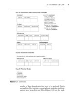
Figures 5.1 through 5.8 show the SQL create table statements that
can be derived from each type of ER or UML model construct. Note that
table names are shown in boldface for readability. Note also that in each
SQL table definition, the term “primary key” represents the key of the
table that is to be used for indexing and searching for data.
5.1.1 Binary Relationships
A one-to-one binary relationship between two entities is illustrated in
Figure 5.1, parts a through c. Note that the UML equivalent binary asso-
ciation is given in Figure 5.2, parts a through c.
When both entities are mandatory (Figure 5.1a), each entity
becomes a table, and the key of either entity can appear in the other
entity’s table as a foreign key. One of the entities in an optional relation-
ship (see Department in Figure 5.1b) should contain the foreign key of
the other entity in its transformed table. Employee, the other entity in
Figure 5.1b, could also contain a foreign key (dept_no) with nulls
allowed, but this would require more storage space because of the much
greater number of Employee entity instances than Department
instances. When both entities are optional (Figure 5.1c), either entity
can contain the embedded foreign key of the other entity, with nulls
allowed in the foreign keys.
The one-to-many relationship can be shown as either mandatory or
optional on the “many” side, without affecting the transformation. On
the “one” side it may be either mandatory (Figure 5.1d) or optional (Fig-
ure 5.1e). In all cases the foreign key must appear on the “many” side,
which represents the child entity, with nulls allowed for foreign keys
only in the optional “one” case. Foreign key constraints are set accord-
ing to the specific meaning of the relationship and may vary from one
relationship to another.
The many-to-many relationship, shown in Figure 5.1f as optional for
both entities, requires a new table containing the primary keys of both
entities. The same transformation applies to either the optional or manda-
tory case, including the fact that the not null clause must appear for the
foreign keys in both cases. Note also that an optional entity means that
the SQL table derived from it may have zero rows for that particular rela-
tionship. This does not affect “null” or “not null” in the table definition.
Teorey.book Page 85 Saturday, July 16, 2005 12:57 PM
@Spy
86 CHAPTER 5 Transforming the Conceptual Data Model to SQL
Figure 5.1 ER model: one-to-one binary relationship between two entities
(b) One-to-one, one entity optional, one mandatory
(a) One-to-one, both entities mandatory
(c) One-to-one, both entities optional
Desktop
Engineer
Employee
managed-by
1
1
has-
allocated
1
1
Department
Abbreviation
Report
1
1
has-abbr
Every department must have a manager, but an
employee can be a manager of at most one department.
Some desktop computers are allocated to engineers,
but not necessarily to all engineers.
Every report has one abbreviation, and every
abbreviation represents exactly one report.
create table
(report_no integer,
report_name varchar(256),
primary key(report_no);
report
create table
(abbr_no char(6),
report_no integer not null unique,
primary key (abbr_no),
foreign key (report_no) references
on delete cascade on update cascade);
abbreviation
report
create table
(dept_no integer,
dept_name char(20),
mgr_id char(10) not null unique,
primary key (dept_no),
foreign key (mgr_id) references
on delete set default on update cascade);
department
employee
create table
(emp_id char(10),
emp_name char(20),
primary key (emp_id));
employee
create table
(emp_id char(10),
desktop_no integer,
primary key (emp_id));
engineer
create table
(desktop_no integer,
emp_id char(10),
primary key (desktop_no),
foreign key (emp_id) references
on delete set null on update cascade);
desktop
engineer
Teorey.book Page 86 Saturday, July 16, 2005 12:57 PM