Database Modeling & Design Fourth Edition- P16 pptx
Bạn đang xem bản rút gọn của tài liệu. Xem và tải ngay bản đầy đủ của tài liệu tại đây (161.74 KB, 5 trang )
62 CHAPTER 4 Requirements Analysis and Conceptual Data Modeling
ing workstation (or computer). Secretaries and managers are each allo-
cated a desktop computer. A pool of desktops and workstations is main-
tained for potential allocation to new employees and for loans while an
employee’s computer is being repaired. Any employee may be married to
another employee, and we want to keep track of these relationships to
avoid assigning an employee to be managed by his or her spouse. This
view is illustrated in Figure 4.3b.
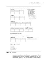
The third view, shown in Figure 4.3c, involves the assignment of
employees, mainly engineers and technicians, to projects. Employees
may work on several projects at one time, and each project could be
headquartered at different locations (cities). However, each employee at
a given location works on only one project at that location. Employee
skills can be individually selected for a given project, but no individual
has a monopoly on skills, projects, or locations.
Figure 4.3 Example of data modeling
is-
managed-by
contains
is-
headed-byhas
1
1
N
1
1
11N
Employee
Department
Division
(a) Management view
Teorey.book Page 62 Saturday, July 16, 2005 12:57 PM
4.3 Conceptual Data Modeling 63
Figure 4.3 (continued)
(b) Employee view
Employee
1
1
1
N
is-
married-to
manages
+
Manager
Desktop Workstation Prof-assoc
Secretary Engineer Technician
d
111
111
N
N
is-allocated is-allocated
belongs-to
has-
allocated
(c) Employee assignment view
Skill
N
N
1
Project
N
N
N
Location
Employee
skill-used
assigned-to
Teorey.book Page 63 Saturday, July 16, 2005 12:57 PM
64 CHAPTER 4 Requirements Analysis and Conceptual Data Modeling
Global ER Schema
A simple integration of the three views over the entity Employee defines
results in the global ER schema (diagram) in Figure 4.3d, which becomes
the basis for developing the normalized tables. Each relationship in the
global schema is based upon a verifiable assertion about the actual data
in the enterprise, and analysis of those assertions leads to the transfor-
mation of these ER constructs into candidate SQL tables, as Chapter 5
shows.
Note that equivalent views and integration could be done for a UML
conceptual model over the class Employee. We will use the ER model for
the examples in the rest of this chapter, however.
The diagram shows examples of binary, ternary, and binary recursive
relationships; optional and mandatory existence in relationships; and
generalization with the disjointness constraint. Ternary relationships
“skill-used” and “assigned-to” are necessary, because binary relation-
ships cannot be used for the equivalent notions. For example, one
employee and one location determine exactly one project (a functional
dependency). In the case of “skill-used,” selective use of skills to projects
cannot be represented with binary relationships (see Section 6.5).
The use of optional existence, for instance, between Employee and
Division or between Employee and Department, is derived from our gen-
eral knowledge that most employees will not be managers of any divi-
sion or department. In another example of optional existence, we show
that the allocation of a workstation to an engineer may not always
occur, nor will all desktops or workstations necessarily be allocated to
someone at all times. In general, all relationships, optional existence
constraints, and generalization constructs need to be verified with the
end user before the ER model is transformed to SQL tables.
In summary, the application of the ER model to relational database
design offers the following benefits:
• Use of an ER approach focuses end users’ discussions on impor-
tant relationships between entities. Some applications are charac-
terized by counterexamples affecting a small number of instances,
and lengthy consideration of these instances can divert attention
from basic relationships.
• A diagrammatic syntax conveys a great deal of information in a
compact, readily understandable form.
• Extensions to the original ER model, such as optional and manda-
tory membership classes, are important in many relationships.
Teorey.book Page 64 Saturday, July 16, 2005 12:57 PM
4.3 Conceptual Data Modeling 65
(d)
Figure 4.3 (continued)
belongs-to
N
N
is-allocated
1
1
has-
allocated
1
1
is-
managed-by
contains
is-
headed-byhas
d
N
N
1
1
N
1
1
11
1N
Employee
N
1
Project
TechnicianEngineerSecretaryManager
Prof-assocWorkstationDesktop
skill-used
assigned-to
is-
married-to
manages
1
1
N
+
Department
Division
N
N
Location
Skill
is-allocated
1
1
Teorey.book Page 65 Saturday, July 16, 2005 12:57 PM
66 CHAPTER 4 Requirements Analysis and Conceptual Data Modeling
Generalization allows entities to be grouped for one functional
role or to be seen as separate subtypes when other constraints are
imposed.
• A complete set of rules transforms ER constructs into mostly nor-
malized SQL tables, which follow easily from real-world require-
ments.
4.4 View Integration
A critical part of the database design process is step II(b), the integration
of different user views into a unified, nonredundant global schema. The
individual end-user views are represented by conceptual data models,
and the integrated conceptual schema results from sufficient analysis of
the end-user views to resolve all differences in perspective and terminol-
ogy. Experience has shown that nearly every situation can be resolved in
a meaningful way through integration techniques.
Schema diversity occurs when different users or user groups develop
their own unique perspectives of the world or, at least, of the enterprise
to be represented in the database. For instance, the marketing division
tends to have the whole product as a basic unit for sales, but the engi-
neering division may concentrate on the individual parts of the whole
product. In another case, one user may view a project in terms of its
goals and progress toward meeting those goals over time, but another
user may view a project in terms of the resources it needs and the per-
sonnel involved. Such differences cause the conceptual models to seem
to have incompatible relationships and terminology. These differences
show up in conceptual data models as different levels of abstraction,
connectivity of relationships (one-to-many, many-to-many, and so on),
or as the same concept being modeled as an entity, attribute, or relation-
ship, depending on the user’s perspective.
As an example of the latter case, in Figure 4.4 we see three different
perspectives of the same real-life situation—the placement of an order
for a certain product. The result is a variety of schemas. The first schema
(Figure 4.4a) depicts Customer, Order, and Product as entities and
“places” and “for-a” as relationships. The second schema (Figure 4.4b),
however, defines “orders” as a relationship between Customer and Prod-
uct and omits Order as an entity altogether. Finally, in the third case
(Figure 4.4c), the relationship “orders” has been replaced by another
relationship, “purchases”; “order-no,” the identifier (key) of an order, is
designated as an attribute of the relationship “purchases.” In other
Teorey.book Page 66 Saturday, July 16, 2005 12:57 PM