Database Modeling & Design Fourth Edition- P12 ppsx
Bạn đang xem bản rút gọn của tài liệu. Xem và tải ngay bản đầy đủ của tài liệu tại đây (176.37 KB, 5 trang )
42 CHAPTER 3 The Unified Modeling Language (UML)
Figure 3.5 illustrates another example of a n-ary relationship. The n-
ary relationship may be clarified by specifying roles next to the partici-
pating classes. A Student is an enrollee in a class, associated with a given
Room location, scheduled Day, and meeting Time.
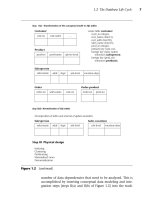
The concept of a primary key arises in the context of database
design. Often, each row of a table is uniquely identified by the values
contained in one or more columns designated as the primary key.
Objects in software are not typically identified in this fashion. As a
result, UML does not have an icon representing a primary key. However,
UML is extensible. The meaning of an element in UML may be extended
Figure 3.5 UML n-ary relationship (parallel to Figure 2.7)
Figure 3.6 UML constructs illustrating primary keys
Day
Course
Student
TimeRoom
enrollee
class
scheduled
daylocation
meeting
time
Car
«pk» vin
mileage
color
Primary key as a stereotype
Composition example
with primary keys
Invoice
«pk» inv_num
customer_id
inv_date
LineItem
«pk» inv_num
«pk» line_num
description
amount
1 *
Teorey.book Page 42 Saturday, July 16, 2005 12:57 PM
3.1 Class Diagrams 43
with a stereotype. Stereotypes are depicted with a short natural language
word or phrase, enclosed in guillemets: « and ». We take advantage of
this extensibility, using a stereotype «pk» to designate primary key
attributes. Figure 3.6 illustrates the stereotype mechanism. The vin
attribute is specified as the primary key for Cars. This means that a given
vin identifies a specific Car. A noteworthy rule of thumb for primary
keys: when a composition relationship exists, the primary key of the
part includes the primary key of the owning object. The second diagram
in Figure 3.6 illustrates this point.
3.1.3 Example from the Music Industry
Large database schemas may be introduced with high-level diagrams.
Details can be broken out in additional diagrams. The overall goal is to
present ideas in a clear, organized fashion. UML offers notational varia-
tions and organizational mechanism. You will sometimes find that
there are multiple ways of representing the same material in UML. The
decisions you make with regard to your representation depend in part
on your purpose for a given diagram. Figures 3.7 through 3.10 illus-
trate some of the possibilities, with an example drawn from the music
industry.
Packages may be used to organize classes into groups. Packages may
themselves also be grouped into packages. The goal of using packages is
to make the overall design of a system more comprehensible. One use
for packages is to represent a schema. You can then show multiple sche-
mas concisely. Another use for packages is to group related classes
together within a schema, and present the schema clearly. Given a set of
classes, different people may conceptualize different groupings. The divi-
sion is a design decision, with no right or wrong answer. Whatever deci-
sions are made, the result should enhance readability. The notation for a
package is a folder icon, and the contents of a package can be optionally
shown in the body of the folder. If the contents are shown, then the
name of the package is placed in the tab. If the contents are elided, then
the name of the package is placed in the body of the icon.
Figure 3.7 Example of related packages
Music Media Distribution
Teorey.book Page 43 Saturday, July 16, 2005 12:57 PM
44 CHAPTER 3 The Unified Modeling Language (UML)
If the purpose is to illustrate the relationships of the packages, and
the classes are not important at the moment, then it is better to illustrate
with the contents elided. Figure 3.7 illustrates the notation with the
music industry example at a very high level. Music is created and placed
on Media. The Media is then Distributed. There is an association
between Music and Media, and between Media and Distribution.
Let us look at the organization of the classes. The music industry is
illustrated in Figure 3.8 with the classes listed. The Music package con-
tains classes that are responsible for creating the music. Examples of
Groups are the Beatles and the Bangles. Sarah McLachlan and Sting are
Artists. Groups and Artists are involved in creating the music. We will
look shortly at the other classes and how they are related. The Media
Figure 3.8 Example illustrating classes grouped into packages
Figure 3.9 Relationships between classes in the music package
Distribution
Studio
Publisher
RetailStore
Media
MusicMedia
Album
CD
Track
Music
Group
Artist
Composer
Lyricist
Musician
Instrument
Song
Rendition
Artist
Instrument
Song
Group
0 *
1 *1 *
2 *
1
*
*
*
*
Rendition
MusicianComposer Lyricist
0 *
1 *
Teorey.book Page 44 Saturday, July 16, 2005 12:57 PM
3.1 Class Diagrams 45
package contains classes that physically hold the recordings of the
music. The Distribution package contains classes that bring the media to
you.
The contents of a package can be expanded into greater detail. The
relationships of the classes within the Music package are illustrated in
Figure 3.9. A Group is an aggregation of two or more Artists. As indicated
by the multiplicity between Artist and Group, [0 *], an Artist may or
may not be in a Group, and may be in more than one Group. Compos-
ers, Lyricists, and Musicians are different types of Artists. A Song is asso-
ciated with one or more Composers. A Song may not have any Lyricist,
or any number of Lyricists. A Song may have any number of Renditions.
A Rendition is associated with exactly one Song. A Rendition is associ-
ated with Musicians and Instruments. A given Musician-Instrument
combination is associated with any number of Renditions. A specific
Rendition-Musician combination may be associated with any number of
Instruments. A given Rendition-Instrument combination is associated
with any number of Musicians.
A system can be understood more easily by shifting focus to each
package in turn. We turn our attention now to the classes and relation-
ships in the Media package, shown in Figure 3.10. The associated classes
from the Music and Distribution packages are also shown, detailing how
the Media package is related to the other two packages. The Music Media
Figure 3.10 Classes of the media package and related classes
StudioMusic Media
Rendition
Producer
Album CD
Track
Publisher
Group
Artist
Teorey.book Page 45 Saturday, July 16, 2005 12:57 PM
46 CHAPTER 3 The Unified Modeling Language (UML)
is associated with the Group and Artist classes, which are contained in
the Music package shown in Figure 3.8. The Music Media is also associ-
ated with the Publisher, Studio, and Producer classes, which are con-
tained in the Distribution package shown in Figure 3.8. Albums and CDs
are types of Music Media. Albums and CDs are both composed of Tracks.
Tracks are associated with Renditions.
3.2 Activity Diagrams
UML has a full suite of diagram types, each of which fulfills a need for
describing a view of the design. UML activity diagrams are used to specify
the activities and the flow of control in a process. The process may be a
workflow followed by people, organizations, or other physical things.
Alternatively, the process may be an algorithm implemented in software.
The syntax and the semantics of the UML constructs are the same,
regardless of the process described. Our examples draw from workflows
that are followed by people and organizations, since these are more use-
ful for the logical design of databases.
3.2.1 Activity Diagram Notation Description
Activity diagrams include notation for nodes, control flow, and organi-
zation. The icons we are describing here are outlined in Figure 3.11. The
notation is further clarified by example in Section 3.2.2.
The nodes include initial node, final node, and activity node. Any pro-
cess begins with control residing in the initial node, represented as a
solid black circle. The process terminates when control reaches a final
node, represented as a solid black circle surrounded by a concentric cir-
cle (i.e., a bull’s-eye). Activity nodes are states where specified work is
processed. For example, an activity might be named “Generate quote.”
The name of an activity is typically a descriptive verb or short verb
phrase, written inside a lozenge shape. Control resides in an activity
until that activity is completed. Then control follows the outgoing flow.
Control flow icons include flows, decisions, forks, and joins. A flow is
drawn with an arrow. Control flows in the direction of the arrow. Deci-
sion nodes are drawn as a hollow diamond with multiple outgoing
flows. Each flow from a decision node must have a guard condition. A
guard condition is written in brackets next to the flow. Control flows in
exactly one direction from a decision node, and only follows a flow if
the guard condition is true. The guard conditions associated with a deci-
Teorey.book Page 46 Saturday, July 16, 2005 12:57 PM