The Illustrated Network- P6 pot
Bạn đang xem bản rút gọn của tài liệu. Xem và tải ngay bản đầy đủ của tài liệu tại đây (254.01 KB, 10 trang )
feedback is required (most of the feedback is provided in the drafting process). Each
RFC is edited, assigned a number, and available to all. Not all RFCs are standards, even
those that defi ne protocols.
This book will make heavy use of RFCs to explain all aspects of TCP/IP and the
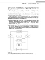
Internet, so a few details are in order. RFCs have various maturity levels that they go
through in their lifetimes, according to their requirement levels. The RFC life-cycle
maturity levels are shown in Figure 1.5. Note that the timeline does not always apply,
or is not applied in a uniform fashion.
A specifi cation can fall into one of six maturity levels, after which it passes to his-
torical status and is useful only for tracking a protocol’s development. Following intro-
duction as an Internet draft, the specifi cation can be a:
Proposed standard—The specification is now well understood, stable, and
sufficiently interesting to the Internet community. The specification is now
usually tested and implemented by several groups, if this has not already
happened at the draft level.
Draft standard—After at least two successful and independent implementations,
the proposed standard is elevated to a draft standard. Without complications,
and with modifications if specific problems are uncovered, draft standards nor-
mally become Internet standards.
Internet Draft
Internet
Standard
Historic RFCs
Informational
RFCs
Experimental
RFCs
Proposed
Standard
Draft Standard
Six months
Four months
FIGURE 1.5
The RFC life cycle. Many experimental RFCs never make it to the standards track.
CHAPTER 1 Protocols and Layers 19
Internet standard—After demonstrations of successful implementation, a draft
standard becomes an Internet standard.
Experimental RFCs—Not all drafts are intended for the “standards track” (and
a huge number are not). Work related to an experimental situation that does
affect Internet operation comprise experimental RFCs. These RFCs should not
be implemented as part of any functional Internet service.
Informational RFCs—Some RFCs contain general, historical, or tutorial informa-
tion rather than instructions.
RFCs are further classifi ed into one of fi ve requirement levels, as shown in Figure 1.6.
Required—These RFCs must be implemented by all Internet systems to ensure
minimum conformance. For example, IPv4 and ICMP, both discussed in detail in
this book, are required protocols. However, there are very few required RFCs.
Recommended—These RFCs are not required for minimum conformance, but are
very useful. For example, FTP is a recommended protocol.
Elective—RFCs in this category are not required and not recommended. However,
systems can use them for their benefit if they like, so they form a kind of
“option set” for Internet protocols.
Limited Use—These RFCs are only used in certain situations. Most experimental
RFCs are in this category.
RFC Requirement Levels
Required: All systems must implement
Recommended: All systems should implement
Elective: Not required nor recommended
Limited Use: Used in certain situations, such as experimental
Not Recommended: Systems should not implement
FIGURE 1.6
RFC requirement levels. There are very few RFCs that are required to implement an Internet
protocol suite.
20 PART I Networking Basics
Not Recommended—These RFCs are inappropriate for general use. Most historic
(obsolete) RFCs are in this category.
RFCs can be found at www.rfc-editor.org/rfc.html. Current Internet drafts can be found
at www.ietf.org/ID.html. Expired Internet drafts can be found at www.watersprings.
org/pub/id/index-all.html.
INTERNET ADMINISTRATION
As the Internet has evolved from an environment with a large student user population
to a more commercialized network with a broad user base, the groups that have guided
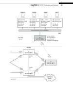
and coordinated Internet issues have evolved. Figure 1.7 shows the general structure
of the Internet administration entities.
Internet Society (ISOC)—This is an international nonprofit organization formed in
1992 to support the Internet standards process. ISOC maintains and supports
the other administrative bodies described in this section. ISOC also supports
research and scholarly activities relating to the Internet.
Internet Society
Internet Architecture Board
Internet Engineering Task Force
IESG
Area
Area
IRSG
Research
Group
Working
Group
Working
Group
Working
Group
Working
Group
Research
Group
Internet Research Task Force
FIGURE 1.7
Internet administration groups, showing the interactions between the major components.
CHAPTER 1 Protocols and Layers 21
Internet Architecture Board (IAB)—This group is the technical advisor to
ISOC. The IAB oversees the continued development of the Internet protocol
suite and plays a technical advisory role to members of the Internet commu-
nity involved in research. The IAB does this primarily through the two organi-
zations under it. In addition, the RFC editor derives authority from the IAB, and
the IAB represents the Internet to other standards organizations and forums.
Internet Engineering Task Force (IETF)—This a forum of working groups
managed by the Internet Engineering Steering Group (IESG). The IETF identi-
fies operational problem areas and proposes solutions. They also develop and
review the specifications intended to become Internet standards. The working
groups are organized into areas devoted to a particular topic. Nine areas have
been defined, although this can change: applications, Internet protocols,
routing, operations, user services, network management, transport, IPv6, and
security. The IETF has taken on some of the roles that were invested in ISOC.
Internet Research Task Force (IRTF)—This is another forum of working groups,
organized directly under the Internet Research Steering Group (IESG) for
management purposes. The IRTF is concerned with long-term research topics
related to Internet protocols, applications, architecture, and technology.
Two other groups are important for Internet administration, although they do not
appear in Figure 1.7.
Internet Corporation for Assigned Names and Numbers (ICANN)—This is a
private nonprofit corporation that is responsible for the management of all
Internet domain names (more on these later) and Internet addresses. Before
1998, this role was played by the Internet Assigned Numbers Authority (IANA),
which was supported by the U.S. government.
Internet Network Information Center (InterNIC)—The job of the InterNIC, run
by the U.S. Department of Commerce, is to collect and distribute information
about IP names and addresses. They are at .
LAYERS
When it comes to communications, all of these standard organizations have one
primary function: the creation of standards that can be combined with others to create
a working network. One concern is that these organizations be able to recommend
solutions that are both fl exible and complete, even though no single standards entity
has complete control over the entire process from top to bottom. The way this is done
is to divide the communications process up into a number of functional layers.
Data communication networks rely on layered protocols. In brief, processes run-
ning on a system and the communication ports that send and receive network bits are
logically connected by a series of layers, each performing one major function of the
networking task.
22 PART I Networking Basics
The key concept is that each layer in the protocol stack has a distinct purpose and
function. There is a big difference between the application layer protocols we’ve seen,
such as FTP and SSH, and a lower-level protocol such as Ethernet on a LAN. Each proto-
col layer handles part of the overall task.
For example, Ethernet cards format the bits sent out on a LAN at one layer, and
FTP client software communicates with the FTP server at a higher layer. However, the
Ethernet card does not tell the FTP application which bits to send out the interface.
FTP addresses the higher-end part of the puzzle: sending commands and data to the
FTP server. Other layers take care of things like formatting, and can vary in capability
or form to address differences at every level. You don’t use different Web browsers
depending on the type of links used on a network. The whole point is that not all
networks are Ethernet (for example), so a layered protocol allows a “mix and match” of
whatever protocols are needed for the network at each layer.
Simple Networking
Most programming languages include statements that allow the programmer to send
bits out of a physical connector. For example, suppose a programming language allowed
you to program a statement like write(port 20$, "test 1"). Sure enough, when com-
piled, linked, and run, the program would spit the bits representing the string “test 1”
out the communications port of the computer. A similar statement like read(port 20$,
STUFF) would, when compiled, linked, and run, wait until something appeared in the
buffer of the serial port and store the bits in the variable called STUFF.
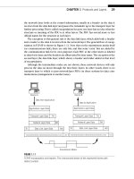
A simple network using this technique is shown in Figure 1.8. (There is still some
software in use that does networking this way.)
However, there are some things to consider. Is there anything attached to the port at
all? Or are the bits just falling into the “bit bucket”? If there was a link attached, what if
someone disconnected it while the bits are in fl ight? What about other types of errors?
How would we know that the bits arrived safely?
Even assuming that the bits got there, and some listening process received them,
does the content make sense? Some computers store bits differently than others, and
“test 1” could be garbled on the other system. How many bits are sent to represent the
System A
(sender)
System B
(receiver)
read (port 20$, STUFF)write (port 20$, “test 1”)
Bi
ts
FIGURE 1.8
An extremely simple network with a distinctly non-layered approach to networking.
CHAPTER 1 Protocols and Layers 23
number 1? How do we know that a “short integer” used by the sender is the same as
the “short integer” used by another? (In fairness, TCP/IP does little to address this issue
directly.)
We see that the networking task is not as simple as it seems. Now, each and every
networked application program could conceivably include every line of code that is
needed to solve all of these issues (and there are even others), but that introduces
another factor into the networking equation. Most hosts attached to a network have
only one communications port active at any one time (the “network interface”). If an
“all-in-one” network application is using it, perhaps to download a music fi le, how can
another application use the same port for email? It can’t.
Besides the need to multiplex in various ways, another factor infl uencing layers
is that modern operating systems do not allow direct access to hardware. The need to
go through the operating system and multiplex the network interface leads to a cen-
tralization of the networking tasks in the end system.
Protocol layers make all of these issues easier to deal with, but they cannot be added
haphazardly. (You can still create a huge and ugly “layer” that implements everything
from hardware to transport to data representation, but it would work.) As important
as the layers are, the tasks and responsibilities assigned to those layers are even more
important.
Protocol Layers
Each layer has a separate function in the overall task of moving bits between
processes. These processes could be applications on separate systems, but on modern
systems a lot of process-to-process communication is not host-to-host. For example, a
lot of printer management software runs as a Web browser using a special loopback
TCP/IP address to interface with the process that gathered status information from the
printer.
As long as the boundary functions between adjacent layers are respected, layers
can be changed or even completely rewritten without having to change the whole
application. Layers can be combined for effi ciency, “mixed-and-matched” from different
vendors, or customized for different circumstances, all without having to rework the
entire stack from top to bottom.
Nearly every layer has some type of multiplexing fi eld to allow the receiver to
determine the type of payload, or content of the data unit at a particular layer. A key
point in networking is that the payload and control information at one layer is just a
“transparent” (meaningless) payload to the layer below. Transparent bits, as the name
implies, are passed unchanged to the next layer.
How can protocol layers work together? Introducing a bunch of new interfaces and
protocols seems to have made the networking task harder, not easier. There is a sim-
ple method called encapsulation that makes the entire architecture workable. What
is encapsulation? Think of the layers of the protocol suite in terms of writing a letter
and the systems that are involved in letter delivery. The letter goes inside an envelope
which is gathered with others inside a mailbag which is transported with others inside
24 PART I Networking Basics
a truck or plane. It sounds like a very complicated way to deliver one message, but
this system makes the overall task of delivering many messages easier, not harder. For
example, there now can be facilities that only deal with mailbags and do not worry
about an individual letter’s language or the transportation details.
THE TCP/IP PROTOCOL SUITE
The protocol stack used on the Internet is the Internet Protocol Suite. It is usually
called TCP/IP after two of its most prominent protocols, but there are other proto-
cols as well. The TCP/IP model is based on a fi ve-layer model for networking. From
bottom (the link) to top (the user application), these are the physical, data link, net-
work, transport, and application layers. Not all layers are completely defi ned by the
model, so these layers are “fi lled in” by external standards and protocols. The layers
have names but no numbers, and although sometimes people speak of “Layer 2” or
“Layer 3,” these are not TCP/IP terms. Terms like these are actually from the OSI Refer-
ence Model.
The TCP/IP stack is open, which means that there are no “secrets” as to how it
works. (There are “open systems” too, but with TCP/IP, the systems do not have to be
“open” and often are not.) Two compatible end-system applications can communicate
regardless of their underlying architectures, although the connections between layers
are not defi ned.
The OSI Reference Model
The TCP/IP or Internet model is not the only standard way to build a protocol suite
or stack. The Open Standard Interconnection (OSI ) reference model is a seven-
layer model that loosely maps into the fi ve layers of TCP/IP. Until the Web became
widely popular in the 1990s, the OSI reference model, with distinctive names and
numbers for its layers, was proposed as the standard model for all communication
networks. Today, the OSI reference model (OSI-RM) is often used as a learning tool
to introduce the functions of TCP/IP.
The TCP/IP stack is comprised of modules. Each module provides a specifi c
function, but the modules are fairly independent. The TCP/IP layers contain relatively
independent protocols that can be used depending on the needs of the system to
provide whatever function is desired. In TCP/IP, each higher layer protocol is sup-
ported by lower layer protocols. The whole collection of protocols forms a type of
hourglass shape, with IP in the middle, and more and more protocols up or down
from there.
CHAPTER 1 Protocols and Layers 25
The TCP/IP Layers
The TCP/IP protocol stack models a series of protocol layers for networks and systems
that allows communications between any types of devices. The model consists of fi ve
separate but related layers, as shown in Figure 1.9. The Internet protocol suite is based
on these fi ve layers. TCP/IP says most about the network and transport layers, and a
lot about the application layer. TCP/IP also defi nes how to interface the network layer
with the data link and physical layers, but is not directly concerned with these two
layers themselves.
The Internet protocol suite assumes that a layer is there and available, so TCP/IP
does not defi ne the layers themselves. The stack consist of protocols, not implementa-
tions, so describing a layer or protocols says almost nothing about how these things
should actually be built.
Not all systems on a network need to implement all fi ve layers of TCP/IP. Devices
using the TCP/IP protocol stack fall into two general categories: a host or end system
(ES) and an intermediate node (often a router) or an intermediate system (IS). The
User Application Programs
Application Layer
Transport Layer
Network Layer
Data Link Layer
Physical Layer
Network Link(s)
FIGURE 1.9
The fi ve layers of TCP/IP. Older models often show only four layers, combining the physical and
data link layers.
Suite, Stack, and Model
The term “protocol stack” is often used synonymously with “protocol suite” as an
implementation of a reference model. However, the term “protocol suite” properly
refers to a collection of all the protocols that can make up a layer in the reference
model. The Internet protocol suite is an example of the Internet or TCP/IP refer-
ence model protocols, and a TCP/IP protocol stack implements one or more of
these protocols at each layer.
26 PART I Networking Basics
intermediate nodes usually only involve the fi rst three layers of TCP/IP (although many
of them still have all fi ve layers for other reasons, as we have seen).
In TCP/IP, as with most layered protocols, the most fundamental elements of the
process of sending and receiving data are collected into the groups that become the
layers. Each layer’s major functions are distinct from all the others, but layers can
be combined for performance reasons. Each implemented layer has an interface with
the layers above and below it (except for the application and physical layers, of course)
and provides its defi ned service to the layer above and obtains services from the layer
below. In other words, there is a service interface between each layer, but these are not
standardized and vary widely by operating system.
TCP/IP is designed to be comprehensive and fl exible. It can be extended to meet
new requirements, and has been. Individual layers can be combined for implementation
purposes, as long as the service interfaces to the layers remain intact. Layers can even
be split when necessary, and new service interfaces defi ned. Services are provided to
the layer above after the higher layer provides the lower layer with the command, data,
and necessary parameters for the lower layer to carry out the task.
Layers on the same system provide and obtain services to and from adjacent layers.
However, a peer-to-peer protocol process allows the same layers on different systems to
communicate. The term peer means every implementation of some layer is essentially
equal to all others. There is no “master” system at the protocol level. Communications
between peer layers on different systems use the defi ned protocols appropriate to the
given layer.
In other words, services refer to communications between layers within the same
process, and protocols refer to communications between processes. This can be con-
fusing, so more information about these points is a good idea.
Protocols and Interfaces
It is important to note that when the layers of TCP/IP are on different systems, they
are only connected at the physical layer. Direct peer-to-peer communication between
all other layers is impossible. This means that all data from an application have to fl ow
“down” through all fi ve layers at the sender, and “up” all fi ve layers at the receiver to
reach the correct process on the other system. These data are sometimes called a ser-
vice data unit (SDU).
Each layer on the sending system adds information to the data it receives from the
layer above and passes it all to the layer below (except for the physical layer, which
has no lower layers to rely on in the model and actually has to send the bits in a form
appropriate for the communications link used).
Likewise, each layer on the receiving system unwraps the received message, often
called a protocol data unit (PDU), with each layer examining, using, and stripping off
the information it needs to complete its task, and passing the remainder up to the next
layer (except for the application layer, which passes what’s left off to the application
program itself). For example, the data link layer removes the wrapper meant for it, uses
it to decide what it should do with this data unit, and then passes the remainder up to
the network layer.
CHAPTER 1 Protocols and Layers 27
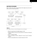
The whole interface and protocol process is shown in Figure 1.10. Although TCP/IP
layers only have names, layer numbers are also used in the fi gure, but only for illustra-
tion. (The numbers come from the ISO-RM.)
As shown in the fi gure, there is a natural grouping of the fi ve-layer protocol stack
at the network layer and the transport layer. The lower three layers of TCP/IP, some-
times called the network support layers, must be present and functional on all systems,
regardless of the end system or intermediate node role. The transport layer links the
upper and lower layers together. This layer can be used to make sure that what was
sent was received, and what was sent is useful to the receiver (and not, for example,
a stray PDU misdirected to the host or unreasonably delayed).
The process of encapsulation makes the whole architecture workable. Encapsu-
lation of one layer’s information inside another layer is a key part of how TCP/IP
works.
Encapsulation
Each layer uses encapsulation to add the information its peer needs on the receiving
system. The network layer adds a header to the information it receives from the trans-
port at the sender and passes the whole unit down to the data link layer. At the receiver,
Intermediate
System (node)
Intermediate
System (node)
Device BDevice A
Application
Transport
Network Network
L3
L2
L1
L3
L2
L1
L3
L2
5
4
3
2
1
5
4–5 Interface
3–4 Interface
2–3 Interface
1–2 Interface
4
3
2
1
L1
Data Link Data Link
Physical
Application
Transport
Network
Data Link
Physical
Network
Data Link
PhysicalPhysical
Peer-to-Peer Protocol at Layer 5
Physical Communication Links
2–3 Interface 2–3 Interface
4–5 Interface
3–4 Interface
2–3 Interface
1–2 Interface
1–2 Interface 1–2 Interface
Peer-to-Peer Protocol at Layer 4
FIGURE 1.10
Protocols and interfaces, showing how devices are only physically connected at the lowest layer
(Layer 1). Note that functionally, intermediate nodes only require the bottom three layers of the
model.
28 PART I Networking Basics