ADOBE INDESIGN CS2 REVEALED- P12 potx
Bạn đang xem bản rút gọn của tài liệu. Xem và tải ngay bản đầy đủ của tài liệu tại đây (1.28 MB, 15 trang )
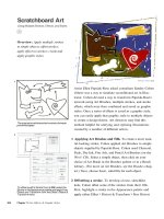
Lesson 3 Work with Graphics Frames INDESIGN 4-31
7. Position the pointer over the document.
The pointer changes to the loaded graphics icon.
8. Click the loaded graphics icon on the F
in the word Flowers.
As shown in Figure 57, the graphic is placed in
a new graphics frame whose top-left corner is
located where the loaded graphics icon was clicked.
You imported two graphics using two subtly different
methods. You created a graphics frame, and then
used the Place command to place a graphic in that
frame. Then, you used the Place command to load a
graphic file, and finally clicked the loaded graphics
icon to create a new frame for the new graphic.
Move a graphic in a
graphics frame
1. Hide the Images layer, show the Background
layer, click the Selection Tool , then click
the Windmills Ghost.psd graphic.
2. Click the top-left reference point on the
proxy in the Transform palette.
3. Click the Direct Selection Tool , position
the tool over the graphic, then click the graphic.
The X and Y fields in the Transform palette
change to X+ and Y+, indicating that the
graphic—not the frame—is selected. When
the Direct Selection Tool is over the graphic,
the pointer changes to a hand icon.
4. Note the width and height of the graphic, as
listed in the Transform palette.
The graphic is substantially larger than the
frame that contains it, thus there are many
areas of the graphic outside the frame that
are not visible through the frame.
(continued)
FIGURE 56
Viewing the placed graphic
FIGURE 57
Viewing the graphic placed with the loaded graphics icon
Placed graphic
Top-left corner of placed graphic
located at same spot where loaded
graphics icon was clicked
INDESIGN 4-32 Working with Frames
5. Press and hold the hand icon on the graphic
until the hand icon changes to a black arrow,
then drag inside the graphics frame, releas-
ing your mouse when the windmill is cen-
tered in the frame, as shown in Figure 58.
The graphic moves within the frame, but the
frame itself does not move. Note that the blue
bounding box, now visible, is the bounding
box for the graphic within the frame.
6. Click the Selection Tool , then click the
graphic.
The orange graphics frame appears and the
blue bounding box of the graphic disap-
pears. Note that the values in the Transform
palette are again specific to the frame only.
7. Click and drag the top-left selection handle
of the graphics frame so that it is aligned with
the top-left corner of the document page.
As shown in Figure 59, the graphic within
the frame does not change size or location.
8. Drag the bottom-right corner of the graphics
frame so that it is aligned with the bottom-
right corner of the document page.
As the frame is enlarged, more of the
graphic within the frame is visible.
9. Click the Direct Selection Tool , click the
graphic, type 0 in the X+ text box in the
Transform palette, type 0 in the Y+ text box,
then press [Enter] (Win) or [return] (Mac).
As shown in Figure 60, the top-left corner of
the graphic is aligned with the top-left cor-
ner of the frame.
You used the Direct Selection Tool and X+ and Y+
values in the Transform palette to move a graphic
within a graphics frame.
FIGURE 58
Viewing the graphic as it is moved in the frame
FIGURE 59
Resizing the graphics frame
FIGURE 60
Viewing the entire graphic in the enlarged frame
Black arrow changes to
white when dragged
Dynamic preview
Top-left corner of bounding box
Graphic does not change size
Resized frame
Lesson 3 Work with Graphics Frames INDESIGN 4-33
Resize graphics frames and
graphics
1. Drag the Background layer below the Text
layer in the Layers palette, then show the
Images layer.
2. Press [A] to access the Direct Selection
Tool, then click the Windmills Color.psd
graphic.
3. Type 50 in the Scale X Percentage text box in
the Transform palette, press [Tab], type 50,
verify that the Scale Y Percentage text box
also contains 50, then press [Enter] (Win) or
[return] (Mac).
The graphic is scaled 50% horizontally and
50% vertically, as shown in Figure 61.
4. Press [V] to access the Selection Tool, then
click the Windmills Color.psd graphic.
The graphics frame was not resized with the
graphic.
5. Click Object on the menu bar, point to
Fitting, then click Fit Frame to Content.
6. Click the top-left reference point on the
proxy in the Transform palette, then click the
Constrain proportions for scaling button
in the Transform palette if necessary.
7. With the frame still selected, type 4.5 in the
X Location text box, type 3 in the Y Location
text box, type 3.32 in the Width text box,
type 2.125 in the Height text box, then press
[Enter] (Win) or [return] (Mac).
(continued)
FIGURE 61
Scaling a graphic
Scale X Percentage
text box
Scale Y Percentage
text box
INDESIGN 4-34 Working with Frames
8. Press [A] to access the Direct Selection
Tool, click the graphic, then note the Scale X
Percentage and Scale Y Percentage text
boxes in the Transform palette.
The graphic was scaled with the frame—it is
no longer at 50% of its original size; the
graphic has been distorted—its X scale per-
centage is larger than its Y scale percentage,
as shown in Figure 62.
TIP When you resize a graphics frame
using the Width and Height text boxes in the
Transform palette, the graphic is resized
with the frame.
9. Click Object on the menu bar, point to
Fitting, then click Fit Content
Proportionally.
The Transform palette now shows that the X
and Y scale percentages are the same.
10.Press [V], then click the graphic.
11.Click Object on the menu bar, point to
Fitting, then click Fit Frame to Content.
As shown in Figure 63, the right edge of the
frame moves left to fit to the right edge of
the graphic.
You scaled a graphic using the Transform palette,
noting that the graphics frame did not change with
the scale. You then scaled the graphics frame with
the Transform palette, noting that the graphic itself
was also scaled—and distorted. Lastly, you used
the Fitting command to fit the graphic proportion-
ally to the new frame size.
FIGURE 62
Noting the X and Y scale percentages
FIGURE 63
Fitting the frame to the content
Image is distorted
Not equal
Lesson 3 Work with Graphics Frames INDESIGN 4-35
Wrap text around a graphic
1. Verify that the Selection Tool is selected,
click the graphic, click the Wrap around
bounding box button in the Text Wrap
palette, type .125 in all four of the Offset text
boxes in the Text Wrap palette, then press
[Enter] (Win) or [return] (Mac).
Your page and Text Wrap palette should
resemble Figure 64.
2. Click anywhere to deselect all, press
[Ctrl][D] (Win) or [D] (Mac), navigate to
the drive and folder where your Data Files
are stored, then double-click Windmills
Silhouette.psd.
3. Click the loaded graphics icon on the F
in the word Flowers.
Windmills Silhouette.psd was saved with a
clipping path named “Path 1” in Photoshop.
4. Click the Wrap around object shape button
in the Text Wrap palette, click the Type
list arrow, click Photoshop Path, then note
that Path 1 is automatically listed in the Path
text box.
As shown in Figure 65, the text wraps
around the graphic’s shape. The Text
Wrap palette specifies a default offset of
.1389 inches for the wrap.
(continued)
FIGURE 64
Wrapping text around a frame’s bounding box
FIGURE 65
Wrapping text around the graphic
.125 inch offset all
around bounding box
Wrap around bounding
box button
Offset values
Wrap around object
shape button
Top Offset value
(applies to
entire path)
INDESIGN 4-36 Working with Frames
5. Type -1.79 in the X Location text box in the
Transform palette, type 1.875 in the Y
Location text box, then press [Enter] (Win)
or [return] (Mac).
As shown in Figure 66, because of the shape
of the path around the graphic, one word
appears in an odd position near the graphic.
6. Click the Direct Selection Tool , then
select the graphic if necessary and click on
its clipping path.
7. Click the Delete Anchor Point Tool , then
click the anchor point circled in Figure 67.
TIP The Delete Anchor Point Tool is
hidden under the Pen Tool
The point is deleted and the reshaped path
leaves no room for the stray word.
(continued)
FIGURE 66
Noting a minor problem with the wrap
FIGURE 67
Identifying the point to be deleted
Stray word
Click with Delete
Anchor Point Tool
Lesson 3 Work with Graphics Frames INDESIGN 4-37
8. Click the Selection Tool , click the
graphic, drag the left-middle handle of the
bounding box to the right so that it abuts
the left edge of the page, then drag the
bottom-middle handle of the bounding box
up so that it abuts the bottom of the page,
as shown in Figure 68.
TIP You may need to reduce the page view
to see the bottom handles on the bounding
box.
9. Click the pasteboard to deselect the frame,
press [W] to change to Preview, then
compare your work to Figure 69.
10.Save your work, then close Flowers.
FIGURE 68
Resizing the graphics frame
FIGURE 69
Viewing the completed document
Drag handle right
LESSON 4
What You’ll Do
INDESIGN 4-38 Working with Frames
Semi-Autoflowing Text
In Chapter 3, you learned how to thread
text manually—to make it flow from text
frame to text frame. When you click the
out port of one text frame with the
Selection Tool, the pointer changes to the
loaded text icon. When you click the
loaded text icon in another text frame, text
flows from the first frame to the second
frame—and the pointer automatically
changes back to the Selection Tool. That’s
great, but what if you wanted to keep man-
ually threading text? Would you need to
repeat the process over and over again?
This is where semi-autoflowing text
comes in. When you are ready to click the
loaded text icon in a text frame where you
want text to flow, press and hold [Alt]
(Win) or [option] (Mac) and then click the
text frame. Text will flow into the text
frame, but the loaded text icon will remain
active—it will not automatically revert
back to the Selection Tool. You can then
thread text into another text frame. In a
nutshell, semi-autoflowing text is a
method for manually threading text
through multiple frames.
Autoflowing Text
You can also autoflow text, which is a
powerful option for quickly adding text to
your document. Let’s say that you create a
six-page document and you specify that
each page has three columns. When you
create the document, the pages have no
text frames on them—they’re just blank,
with columns and margin guides. To auto-
flow text into the document, you click the
Place command and choose the text docu-
ment that you want to import. Once you
choose the document, the pointer
changes to the loaded text icon. If you
press and hold [Shift], the loaded text icon
becomes the autoflow loaded text icon.
When you click the autoflow loaded text
icon in a column, InDesign creates text
frames within column guides on that page
and all subsequent pages, and flows the
text into those frames.
In this lesson, you will explore options for
autoflowing text through a document. You
will also learn how to add column breaks
to text.
▼
WORK WITH
TEXT FRAMES
Lesson 4 Work with Text Frames INDESIGN 4-39
Because you specified that each page has
three columns when you created the docu-
ment, InDesign will create three text
frames in the columns on every page for
the text to flow to. Figure 70 shows a page
with three text frames created by
autoflowing text. Note that if you autoflow
more text than the document can create,
InDesign will add as many pages as neces-
sary to autoflow all of the text. Note also
that, if your document pages contain
objects such as graphics, the text frames
added by the autoflow will be positioned in
front of the graphics already on the page.
As you may imagine, autoflowing text is a
powerful option, but don’t be intimidated
by it. The text frames that are generated
are all editable. You can resize them or
delete them. Nevertheless, you should take
a few moments to practice autoflowing text
to get the hang of it. Like learning how to
ride a bicycle, you can read about it all you
want, but actually doing it is where the
learning happens.
Inserting a Column Break
When you are working with text in
columns, you will often want to move text
from the bottom of one column to the top
of the next. You do this by inserting a col-
umn break. A column break is a typo-
graphic command that forces text to the
next column. The Column Break command
is located within the Insert Break Character
command on the Type menu.
FIGURE 70
Three text frames created in columns by autoflowing text
Using the Story Editor
InDesign has a feature called the Story Editor that makes it easier to edit text in
complex documents. Imagine that you are doing a layout for a single magazine
article. The text for the article is flowed through numerous text frames across
12 pages. Now imagine that you want to edit the text—maybe you want to proofread
it or spell check it. Editing the text within the layout might be difficult—you’d
have to scroll from page to page. Instead, you could use the Edit in Story Editor
command on the Edit menu. This opens a new window, which contains all the text
in a single file—just like a word processing document. Any changes that you make
in the Story Editor window will be immediately updated to the text in the layout. It’s
a great feature!
INDESIGN 4-40 Working with Frames
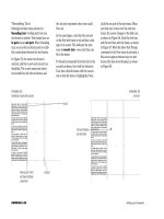
In Figure 71, the headline near the bottom
of the first column would be better posi-
tioned at the top of the next column. By
inserting a column break, you do exactly
that, as shown in Figure 72.
Inserting a “Continued on
page ” Notation
When threading text manually or auto-
flowing text, you will get to a point where
text has filled all the text frames on the
page and continues to another page.
Usually, the text continues onto the next
page—but not always. In many cases, the
next page will be reserved for pictures or
other publication elements, such as tables
or graphs. When the reader gets to the
bottom of the page of text, they need to
know on which page the text is continued.
You can insert a “Continued on page ”
notation to let the reader know where to
go to continue reading.
If you’ve ever read a magazine or news-
paper article, you are familiar with
“Continued on page ” notations. In
InDesign, a page continuation is formatted
as a special character. Simply create a text
frame, then type the words “Continued on
page X.” Select the X, then apply the Next
Page Number command. The X changes to
the page number of the page that contains
the text frame that the text flows into. If for
any reason you move pages within the
Pages palette and page numbers change,
the Next Page Number character will auto-
matically update to show the page number
where the text continues.
The Next Page Number command is
located within the Insert Special Character
command on the Type menu.
There’s one important point you need to
note when creating a “Continued on
page ” notation. By definition, body copy
will reach the end of a text frame on a
given page and be continued on another
page. At the end of the text frame on the
first page, you will need to create a text
frame to contain the “Continued on
page ” notation. In order for the notation
to work—for it to list the page where the
text continues—the top edge of the text
frame that contains the notation must be
touching the frame that contains the body
copy that is to be continued.
FIGURE 72
Viewing text after inserting a column break
FIGURE 71
Viewing text that needs a column break
Text is forced to
top of next column
2
nd
column
Place for
column break
Lesson 4 Work with Text Frames INDESIGN 4-41
Autoflow text
1. Open ID 4-6.indd, save it as Autoflow, then
look at each page in the document.
Other than the text frame that holds the
headline on page 1, there are no text frames
in the document.
2. Click the Selection Tool , double-click
the page 1 icon in the Pages palette,
click File on the menu bar, click Place,
navigate to the drive and folder where your
Data Files are stored, then double-click
Windmill text.doc.
The pointer changes to the loaded text icon.
3. Drag a text frame in the position shown in
Figure 73.
Note that once you have drawn the frame,
the loaded text icon automatically changes
back to the Selection Tool.
4. Click the out port of the text frame, then
position the loaded text icon over the right
column on the page.
5. Press and hold [Alt] (Win) or [option] (Mac]
so that the pointer changes to the semi-
autoflow loaded text icon.
6. Still pressing and holding [Alt] (Win) or
[option] (Mac], click the top-left corner of
the right column, so that the text flows into
the frame.
Because you used the semi-autoflow loaded
text icon, the pointer remains as a loaded
text icon and does not revert back to the
Selection Tool, as shown in Figure 74.
(continued)
FIGURE 73
Creating a text frame using the loaded text icon
FIGURE 74
Flowing text with the semi-autoflow loaded text icon
Pointer remains as
loaded text icon
after text has been
flowed
Aligned with intersection
of margin and guide
Out port
INDESIGN 4-42 Working with Frames
7. Double-click the page 2 icon, then click the
top-left corner of the left column on the page.
A new frame is created and text flows into
the left column.
8. Click the out port of the new text frame on
page 2, then position the pointer over the
right column on page 2.
9. Press and hold [Shift], note the change to
the loaded text icon, then click the top-left
corner of the second column.
InDesign creates text frames within column
guides on all subsequent pages. InDesign
has added new pages to the document to
accommodate the autoflow.
You placed text by clicking and dragging the
loaded text icon to create a new text frame. You
flowed text using the semi-autoflow loaded text
icon and the autoflow loaded text icon.
Reflow text
1. Double-click the page 4 icon in the Pages
palette, then create a horizontal guide at
5.875 in.
2. Click the left text frame to select it, drag the
bottom-middle handle of the text frame’s
bounding box up until it snaps to the guide,
then do the same to the right text frame, so
that your page resembles Figure 75.
The text is reflowed in the document.
3. Double-click the numbers 2-3 in the Pages
palette to center the spread in the document
window, click View on the menu bar, click
Show Text Threads, then click the right text
frame on page 2.
(continued)
FIGURE 75
Resizing text frames
Drag middle handle
up to guide
Lesson 4 Work with Text Frames INDESIGN 4-43
4. With the right frame on page 2 still selected,
press [Delete] (Win) or [delete] (Mac), then
click the text frame remaining on page 2.
As shown in Figure 76, the text is reflowed
from the second text frame on page 2 to the
first text frame on page 3.
5. Press [Ctrl][D](Win) or [D] (Mac), navi-
gate to the drive and folder where your
Data Files are stored, then double-click
2 Windmills.psd.
6. Click the top-left corner of the right column
on page 2.
7. Create a horizontal guide at 5.375 in.
8. Click the text frame on page 2, then click the
out port.
9. Click the intersection between the guide you
created and the left edge of the right col-
umn, beneath the graphic.
As shown in Figure 77, text is now threaded
through the new text frame.
You resized two text frames, noting that text was
reflowed through the document. You deleted a text
frame, then created a text frame, noting that text
continued to flow through the document.
Add a column break
1. Double-click the page 5 icon in the Pages
palette, then delete the two text frames on
page 5.
2. Click Layout on the menu bar, click Margins
and Columns, change the number of
columns to 3, then click OK.
(continued)
FIGURE 76
Flowing text after deleting a text frame
FIGURE 77
Threading text to a new text frame
Text flow continues
between remaining
text frames
Your text may
appear as lines
Click loaded text
icon at intersection
New text frame
INDESIGN 4-44 Working with Frames
3. Press [Ctrl][D](Win) or [D] (Mac), navi-
gate to the drive and folder where your
Chapter 4 Data Files are stored, then double-
click Sidebar copy.doc.
4. Drag the loaded text icon to create a text
frame, as shown in Figure 78.
5. Click Object on the menu bar, click Text
Frame Options, change the number of
columns to 3, then click OK.
6. Click the Type Tool , then click to place
the pointer before the W in Windmill Speeds.
7. Click Type on the menu bar, point to Insert
Break Character, then click Column Break.
The Windmill Speeds text is forced into the
second column.
8. Click before the W in Windmill Productivity,
click Type on the menu bar, point to Insert
Break Character, then click Column Break.
Your page should resemble Figure 79.
You deleted two text frames on a page, then
changed the number of columns on that page. You
then placed text, formatted the text frame to have
three columns, and finally used the Column Break
command to create two new column breaks.
FIGURE 78
Creating a text frame with the loaded text icon
FIGURE 79
Viewing the text frame with column breaks
Guide
Text frame
Lesson 4 Work with Text Frames INDESIGN 4-45
Insert a page continuation
notation
1. Double-click the page 4 icon in the Pages
palette, then create a horizontal guide at 5 in.
2. Click the Selection Tool , click the text
frame in the right column, then drag the bot-
tom middle bounding box handle up until it
snaps to the guide at 5 in.
3. Click the Type Tool , then create a text frame
between the two guides, as shown in Figure 80.
The two text frames both touch each other at
the guide.
4. Click Object on the menu bar, click Text
Frame Options, change the vertical justifica-
tion to Center, then click OK.
5. Click inside the new text box, type (Continued
on Page X), click anywhere within the word
Page, show the Paragraph Styles palette, then
click the style named Continued.
6. Select the letter X, click Type on the menu
bar, point to Insert Special Character, then
click Next Page Number.
The text now reads (Continued on Page 6),
as shown in Figure 81.
7. Click the Selection Tool , click the text frame
above the “Continued” text frame, then verify that
the text does indeed continue on page 6.
8. Save your work, then close Autoflow.
TIP Use the Previous Page Number command
along with “Continued from page . . .” text
to indicate that copy on a page is continued
from a previous page.
You inserted a page continuation notation in the
document.
FIGURE 80
Creating a text frame for the page continuation notation
FIGURE 81
Viewing the page continuation notation
Guides
Text frame
Notation