Mechanical Science Handbooks P3 pps
Bạn đang xem bản rút gọn của tài liệu. Xem và tải ngay bản đầy đủ của tài liệu tại đây (287.75 KB, 30 trang )
DOE-HDBK-1018/2-93
JANUARY 1993
DOE FUNDAMENTALS HANDBOOK
MECHANICAL SCIENCE
Volume 2 of 2
U.S. Department of Energy FSC-6910
Washington, D.C. 20585
Distribution Statement A. Approved for public release; distribution is unlimited.
This document has been reproduced directly from the best available copy.
Available to DOE and DOE contractors from the Office of Scientific and
Technical Information. P.O. Box 62, Oak Ridge, TN 37831.
Available to the public from the National Technical Information Service, U.S.
Department of Commerce, 5285 Port Royal., Springfield, VA 22161.
Order No. DE93012226
DOE-HDBK-1018/2-93
MECHANICAL SCIENCE
ABSTRACT
The Mechanical Science Handbook was developed to assist nuclear facility operating
contractors in providing operators, maintenance personnel, and the technical staff with the
necessary fundamentals training to ensure a basic understanding of mechanical components and
mechanical science. The handbook includes information on diesel engines, heat exchangers,
pumps, valves, and miscellaneous mechanical components. This information will provide
personnel with a foundation for understanding the construction and operation of mechanical
components that are associated with various DOE nuclear facility operations and maintenance.
Key Words: Training Material, Diesel Engine, Heat Exchangers, Pumps, Valves
Rev. 0 ME
DOE-HDBK-1018/2-93
MECHANICAL SCIENCE
FOREWORD
The Department of Energy (DOE) Fundamentals Handbooks consist of ten academic
subjects, which include Mathematics; Classical Physics; Thermodynamics, Heat Transfer, and
Fluid Flow; Instrumentation and Control; Electrical Science; Material Science; Mechanical
Science; Chemistry; Engineering Symbology, Prints, and Drawings; and Nuclear Physics and
Reactor Theory. The handbooks are provided as an aid to DOE nuclear facility contractors.
These handbooks were first published as Reactor Operator Fundamentals Manuals in 1985
for use by DOE category A reactors. The subject areas, subject matter content, and level of
detail of the Reactor Operator Fundamentals Manuals were determined from several sources.
DOE Category A reactor training managers determined which materials should be included, and
served as a primary reference in the initial development phase. Training guidelines from the
commercial nuclear power industry, results of job and task analyses, and independent input from
contractors and operations-oriented personnel were all considered and included to some degree
in developing the text material and learning objectives.
The DOE Fundamentals Handbooks represent the needs of various DOE nuclear facilities'
fundamental training requirements. To increase their applicability to nonreactor nuclear
facilities, the Reactor Operator Fundamentals Manual learning objectives were distributed to the
Nuclear Facility Training Coordination Program Steering Committee for review and comment.
To update their reactor-specific content, DOE Category A reactor training managers also
reviewed and commented on the content. On the basis of feedback from these sources,
information that applied to two or more DOE nuclear facilities was considered generic and was
included. The final draft of each of the handbooks was then reviewed by these two groups. This
approach has resulted in revised modular handbooks that contain sufficient detail such that each
facility may adjust the content to fit their specific needs.
Each handbook contains an abstract, a foreword, an overview, learning objectives, and
text material, and is divided into modules so that content and order may be modified by
individual DOE contractors to suit their specific training needs. Each handbook is supported by
a separate examination bank with an answer key.
The DOE Fundamentals Handbooks have been prepared for the Assistant Secretary for
Nuclear Energy, Office of Nuclear Safety Policy and Standards, by the DOE Training
Coordination Program. This program is managed by EG&G Idaho, Inc.
Rev. 0 ME
DOE-HDBK-1018/2-93
MECHANICAL SCIENCE
OVERVIEW
The Department of Energy Fundamentals Handbook entitled Mechanical Science was
prepared as an information resource for personnel who are responsible for the operation of the
Department's nuclear facilities. Almost all processes that take place in the nuclear facilities
involve the use of mechanical equipment and components. A basic understanding of mechanical
science is necessary for DOE nuclear facility operators, maintenance personnel, and the technical
staff to safely operate and maintain the facility and facility support systems. The information
in the handbook is presented to provide a foundation for applying engineering concepts to the
job. This knowledge will help personnel more fully understand the impact that their actions may
have on the safe and reliable operation of facility components and systems.
The Mechanical Science handbook consists of five modules that are contained in two
volumes. The following is a brief description of the information presented in each module of
the handbook.
Volume 1 of 2
Module 1 - Diesel Engine Fundamentals
Provides information covering the basic operating principles of 2-cycle and
4-cycle diesel engines. Includes operation of engine governors, fuel ejectors, and
typical engine protective features.
Module 2 - Heat Exchangers
Describes the construction of plate heat exchangers and tube and shell heat
exchangers. Describes the flow patterns and temperature profiles in parallel flow,
counter flow, and cross flow heat exchangers.
Module 3 - Pumps
Explains the operation of centrifugal and positive displacement pumps. Topics
include net positive suction head, cavitation, gas binding, and pump characteristic
curves.
Rev. 0 ME
DOE-HDBK-1018/2-93
MECHANICAL SCIENCE
OVERVIEW (Cont.)
Volume 2 of 2
Module 4 - Valves
Introduces the functions of the basic parts common to most types of valves.
Provides information on applications of many types of valves. Types of valves
covered include gate valves, globe valves, ball valves, plug valves, diaphragm
valves, reducing valves, pinch valves, butterfly valves, needle valves, check
valves, and safety/relief valves.
Module 5 - Miscellaneous Mechanical Components
Provides information on significant mechanical devices that have widespread
application in nuclear facilities but do not fit into the categories of components
covered by the other modules. These include cooling towers, air compressors,
demineralizers, filters, strainers, etc.
The information contained in this handbook is not all encompassing. An attempt to
present the entire subject of mechanical science would be impractical. However, the Mechanical
Science
handbook presents enough information to provide the reader with the fundamental
knowledge necessary to understand the advanced theoretical concepts presented in other subject
areas, and to understand basic system and equipment operation.
Rev. 0 ME
Department of Energy
Fundamentals Handbook
MECHANICAL SCIENCE
Module 4
Valves
Valves DOE-HDBK-1018/2-93 TABLE OF CONTENTS
TABLE OF CONTENTS
LIST OF FIGURES iii
LIST OF TABLES v
REFERENCES vi
OBJECTIVES vii
VALVE FUNCTIONS AND BASIC PARTS 1
Introduction 1
Valve Body 2
Valve Bonnet 3
Valve Trim 3
Valve Actuator 5
Valve Packing 5
Introduction to the Types of Valves 6
Summary 7
TYPES OF VALVES 8
Gate Valves 8
Gate Valve Disk Design 10
Gate Valve Stem Design 14
Gate Valve Seat Design 14
Globe Valves 15
Globe Valve Body Designs 16
Globe Valve Disks 17
Globe Valve Disk and Stem Connections 18
Globe Valve Seats 18
Globe Valve Direction of Flow 18
Ball Valves 18
Ball Valve Stem Design 20
Ball Valve Bonnet Design 20
Ball Valve Position 20
Plug Valves 21
Plug Ports 22
Multiport Plug Valves 22
Plug Valve Disks 22
Lubricated Plug Valve Design 23
Nonlubricated Plugs 23
Rev. 0 Page i ME-04
TABLE OF CONTENTS DOE-HDBK-1018/2-93 Valves
TABLE OF CONTENTS (Cont.)
Manually Operated Plug Valve Installation 24
Plug Valve Glands 24
Diaphragm Valves 24
Diaphragm Construction 25
Diaphragm Valve Stem Assemblies 27
Diaphragm Valve Bonnet Assemblies 27
Reducing Valves 28
Pinch Valves 30
Pinch Valve Bodies 31
Butterfly Valves 31
Butterfly Valve Seat Construction 32
Butterfly Valve Body Construction 32
Butterfly Valve Disk and Stem Assemblies 32
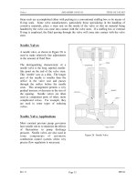
Needle Valves 33
Needle Valve Applications 33
Needle Valve Body Designs 34
Check Valves 35
Swing Check Valves 35
Tilting Disk Check Valves 36
Lift Check Valves 37
Piston Check Valves 38
Butterfly Check Valves 39
Stop Check Valves 40
Relief And Safety Valves 40
Pilot-Operated Relief Valves 42
Summary 43
VALVE ACTUATORS 44
Introduction 44
Manual, Fixed, and Hammer Actuators 44
Electric Motor Actuators 46
Pneumatic Actuators 47
Hydraulic Actuators 47
Self-Actuated Valves 48
Solenoid Actuated Valves 48
Speed of Power Actuators 49
Valve Position Indication 49
Summary 50
ME-04 Page ii Rev. 0
Valves DOE-HDBK-1018/2-93 LIST OF FIGURES
LIST OF FIGURES
Figure 1 Basic Parts of a Valve 2
Figure 2 Rising Stems 4
Figure 3 Nonrising Stems 5
Figure 4 Gate Valve 9
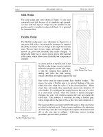
Figure 5 Solid Wedge Gate Valve 11
Figure 6 Flexible Wedge Gate Valve 11
Figure 7 Split Wedge Gate Valve 12
Figure 8 Parallel Disk Gate Valve 13
Figure 9 Z-Body Globe Valve 15
Figure 10 Y-Body Globe Valve 16
Figure 11 Angle Globe Valve 17
Figure 12 Typical Ball Valve 19
Figure 13 Plug Valve 21
Figure 14 Straight-Through Diaphragm Valve 24
Figure 15 Weir Diaphragm Valve 26
Figure 16 Variable Reducing Valve 28
Figure 17 Non-Variable Reducing Valve 29
Figure 18 Pinch Valves 30
Figure 19 Typical Butterfly Valve 31
Figure 20 Needle Valve 33
Rev. 0 Page iii ME-04
LIST OF FIGURES DOE-HDBK-1018/2-93 Valves
LIST OF FIGURES (Cont.)
Figure 21 Bar-Stock Instrument Valve 34
Figure 22 Swing Check Valve 35
Figure 23 Operation of Tilting Disk Check Valve 36
Figure 24 Lift Check Valve 37
Figure 25 Piston Check Valve 38
Figure 26 Butterfly Check Valve 39
Figure 27 Stop Check Valve 40
Figure 28 Relief Valve 41
Figure 29 Safety Valve 42
Figure 30 Fixed Handwheel 44
Figure 31 Hammer Handwheel 45
Figure 32 Manual Gear Head 45
Figure 33 Electric Motor Actuator 46
Figure 34 Pneumatic Actuator 47
Figure 35 Solenoid Actuated Valve 48
ME-04 Page iv Rev. 0
Valves DOE-HDBK-1018/2-93 LIST OF TABLES
LIST OF TABLES
None
Rev. 0 Page v ME-04
REFERENCES DOE-HDBK-1018/2-93 Valves
REFERENCES
Babcock & Wilcox, Steam, Its Generation and Use, Babcock & Wilcox Co., 1978.
Cheremisinoff, N. P., Fluid Flow, Pumps, Pipes and Channels, Ann Arbor Science.
Heat Transfer, Thermodynamics and Fluid Flow Fundamentals, Columbia, MD, General
Physics Corporation, Library of Congress Card #A 326517, 1982.
Schweitzer, Philip A., Handbook of Valves, Industrial Press Inc.
Stewart, Harry L., Pneumatics & Hydraulics, Theodore Audel & Company, 1984.
ME-04 Page vi Rev. 0
Valves DOE-HDBK-1018/2-93 OBJECTIVES
TERMINAL OBJECTIVE
1.0 Without references, DESCRIBE the construction and operation of a given type of valve,
valve component, or valve actuator, as presented in this module.
ENABLING OBJECTIVES
1.1 DESCRIBE the four basic types of flow control elements employed in valve design.
1.2 DESCRIBE how valve stem leakage is controlled.
1.3 Given a drawing of a valve, IDENTIFY the following:
a. Body
b. Bonnet
c. Stem
d. Actuator
e. Packing
f. Seat
g. Disk
1.4 Given a drawing of a valve, IDENTIFY each of the following types of valves:
a. Globe
b. Gate
c. Plug
d. Ball
e. Needle
f. Butterfly
g. Diaphragm
h. Pinch
i. Check
j. Stop check
k. Safety/relief
l. Reducing
1.5 DESCRIBE the application of the following types of valves:
a. Globe
b. Gate
c. Plug
d. Ball
e. Needle
f. Butterfly
g. Diaphragm
h. Pinch
i. Check
j. Safety/relief
k. Reducing
1.6 DESCRIBE the construction and principle of operation for the following types of valve
actuators:
a. Manual
b. Electric motor
c. Pneumatic
d. Hydraulic
e. Solenoid
Rev. 0 Page vii ME-04
DOE-HDBK-1018/2-93 Valves
Intentionally Left Blank.
ME-04 Page viii Rev. 0
Valves DOE-HDBK-1018/2-93 VALVE FUNCTIONS AND BASIC PARTS
VALVE FUNCTIONS AND BASIC PARTS
Valves are the most common single piece of equipment found in DOE facilities.
Although there are many types, shapes, and sizes of valves, they all have the
same basic parts. This chapter will review the common parts and functions of a
valve.
EO 1.1 DESCRIBE the four basic types of flow control elements
employed in valve design.
EO 1.2 DESCRIBE how valve stem leakage is controlled.
EO 1.3 Given a drawing of a valve, IDENTIFY the following:
a. Body
b. Bonnet
c. Stem
d. Actuator
e. Packing
f. Seat
g. Disk
Introduction
A valve is a mechanical device that controls the flow of fluid and pressure within a system or
process. A valve controls system or process fluid flow and pressure by performing any of the
following functions:
Stopping and starting fluid flow
Varying (throttling) the amount of fluid flow
Controlling the direction of fluid flow
Regulating downstream system or process pressure
Relieving component or piping over pressure
There are many valve designs and types that satisfy one or more of the functions identified
above. A multitude of valve types and designs safely accommodate a wide variety of industrial
applications.
Regardless of type, all valves have the following basic parts: the body, bonnet, trim (internal
elements), actuator, and packing. The basic parts of a valve are illustrated in Figure 1.
Rev. 0 ME-04
Page 1
VALVE FUNCTIONS AND BASIC PARTS DOE-HDBK-1018/2-93 Valves
Valve Body
The body, sometimes called the shell, is the primary pressure boundary of a valve. It serves as
the principal element of a valve assembly because it is the framework that holds everything
together.
The body, the first pressure boundary of a valve, resists fluid pressure loads from connecting
piping. It receives inlet and outlet piping through threaded, bolted, or welded joints.
Valve bodies are cast or forged into a
Figure 1 Basic Parts of a Valve
variety of shapes. Although a sphere
or a cylinder would theoretically be
the most economical shape to resist
fluid pressure when a valve is open,
there are many other considerations.
For example, many valves require a
partition across the valve body to
support the seat opening, which is the
throttling orifice. With the valve
closed, loading on the body is
difficult to determine. The valve end
connections also distort loads on a
simple sphere and more complicated
shapes. Ease of manufacture,
assembly, and costs are additional
important considerations. Hence, the
basic form of a valve body typically
is not spherical, but ranges from
simple block shapes to highly
complex shapes in which the bonnet,
a removable piece to make assembly
possible, forms part of the pressure-
resisting body.
Narrowing of the fluid passage
(venturi effect) is also a common
method for reducing the overall size
and cost of a valve. In other
instances, large ends are added to the
valve for connection into a larger
line.
ME-04 Rev. 0
Page 2
Valves DOE-HDBK-1018/2-93 VALVE FUNCTIONS AND BASIC PARTS
Valve Bonnet
The cover for the opening in the valve body is the bonnet. In some designs, the body itself is
split into two sections that bolt together. Like valve bodies, bonnets vary in design. Some
bonnets function simply as valve covers, while others support valve internals and accessories
such as the stem, disk, and actuator.
The bonnet is the second principal pressure boundary of a valve. It is cast or forged of the same
material as the body and is connected to the body by a threaded, bolted, or welded joint. In all
cases, the attachment of the bonnet to the body is considered a pressure boundary. This means
that the weld joint or bolts that connect the bonnet to the body are pressure-retaining parts.
Valve bonnets, although a necessity for most valves, represent a cause for concern. Bonnets can
complicate the manufacture of valves, increase valve size, represent a significant cost portion
of valve cost, and are a source for potential leakage.
Valve Trim
The internal elements of a valve are collectively referred to as a valve's trim. The trim typically
includes a disk, seat, stem, and sleeves needed to guide the stem. A valve's performance is
determined by the disk and seat interface and the relation of the disk position to the seat.
Because of the trim, basic motions and flow control are possible. In rotational motion trim
designs, the disk slides closely past the seat to produce a change in flow opening. In linear
motion trim designs, the disk lifts perpendicularly away from the seat so that an annular orifice
appears.
Disk and Seat
For a valve having a bonnet, the disk is the third primary principal pressure boundary.
The disk provides the capability for permitting and prohibiting fluid flow. With the disk
closed, full system pressure is applied across the disk if the outlet side is depressurized.
For this reason, the disk is a pressure-retaining part. Disks are typically forged and, in
some designs, hard-surfaced to provide good wear characteristics. A fine surface finish
of the seating area of a disk is necessary for good sealing when the valve is closed. Most
valves are named, in part, according to the design of their disks.
The seat or seal rings provide the seating surface for the disk. In some designs, the body
is machined to serve as the seating surface and seal rings are not used. In other designs,
forged seal rings are threaded or welded to the body to provide the seating surface. To
improve the wear-resistance of the seal rings, the surface is often hard-faced by welding
and then machining the contact surface of the seal ring. A fine surface finish of the
seating area is necessary for good sealing when the valve is closed. Seal rings are not
usually considered pressure boundary parts because the body has sufficient wall thickness
to withstand design pressure without relying upon the thickness of the seal rings.
Rev. 0 ME-04
Page 3
VALVE FUNCTIONS AND BASIC PARTS DOE-HDBK-1018/2-93 Valves
Stem
The stem, which connects the actuator and disk, is responsible for positioning the disk.
Stems are typically forged and connected to the disk by threaded or welded joints. For
valve designs requiring stem packing or sealing to prevent leakage, a fine surface finish
of the stem in the area of the seal is necessary. Typically, a stem is not considered a
pressure boundary part.
Connection of the disk to the stem can allow some rocking or rotation to ease the
positioning of the disk on the seat. Alternately, the stem may be flexible enough to let
the disk position itself against the seat. However, constant fluttering or rotation of a
flexible or loosely connected disk can destroy the disk or its connection to the stem.
Two types of valve stems are rising stems and nonrising stems. Illustrated in Figures 2
and 3, these two types of stems are easily distinguished by observation. For a rising stem
valve, the stem will rise above the actuator as the valve is opened. This occurs because
the stem is threaded and mated with the bushing threads of a yoke that is an integral part
of, or is mounted to, the bonnet.
Figure 2 Rising Stems
ME-04 Rev. 0
Page 4
Valves DOE-HDBK-1018/2-93 VALVE FUNCTIONS AND BASIC PARTS
Figure 3 Nonrising Stems
There is no upward stem movement from outside the valve for a nonrising stem design.
For the nonrising stem design, the valve disk is threaded internally and mates with the
stem threads.
Valve Actuator
The actuator operates the stem and disk assembly. An actuator may be a manually operated
handwheel, manual lever, motor operator, solenoid operator, pneumatic operator, or hydraulic
ram. In some designs, the actuator is supported by the bonnet. In other designs, a yoke
mounted to the bonnet supports the actuator.
Except for certain hydraulically controlled valves, actuators are outside of the pressure boundary.
Yokes, when used, are always outside of the pressure boundary.
Valve Packing
Most valves use some form of packing to prevent leakage from the space between the stem and
the bonnet. Packing is commonly a fibrous material (such as flax) or another compound (such
as teflon) that forms a seal between the internal parts of a valve and the outside where the stem
extends through the body.
Valve packing must be properly compressed to prevent fluid loss and damage to the valve's
stem. If a valve's packing is too loose, the valve will leak, which is a safety hazard. If the
packing is too tight, it will impair the movement and possibly damage the stem.
Rev. 0 ME-04
Page 5