CREATING GAME ART FOR 3D ENGINES- P7 ppsx
Bạn đang xem bản rút gọn của tài liệu. Xem và tải ngay bản đầy đủ của tài liệu tại đây (1.71 MB, 30 trang )
Find:
function onServerCreated()
Edit:
exec(“./crossbow.cs”);
To read:
exec(“./raygun.cs”);
Find:
// Starting equipment
Edit:
%player.setInventory(Crossbow,1);
%player.setInventory(CrossbowAmmo,100);
%player.mountImage(CrossbowImage,0);
To read:
%player.setInventory(RayGun,1);
%player.setInventory(RayGunAmmo,100);
%player.mountImage(RayGunImage,0);
Editing Player.cs
Player.cs is the script file that sets many of the parameters that the main character
in the game uses. Here, two inventory lines are being added.
Find:
//Allowable Inventory Items
Then add these lines:
maxInv[RayGunAmmo] = 50;
maxInv[RayGun] = 1;
158 Creating Game Art for 3D Engines
Chapter 6 Exporting Game Art 159
Editing AiPlayer.cs
The example given here applies if you want to assign the raygun to both the player
and the AI player (the character that the computer controls). In Chapter 12,
“Character Exporting,” another scenario is presented, in which a new player defini-
tion is created for the AI player. This scenario uses a robot character mesh and a
blaster instead of a raygun.
Find:
function AIManager::spawn
Edit:
%player.mountImage(CrossbowImage,0);
%player.setInventory(CrossbowAmmo,1000);
To read:
%player.mountImage(RayGunImage,0);
%player.setInventory(RayGunAmmo,1000);
The raygun data files are located in Scripts\Data\Shapes\Raygun on the compan-
ion CD-ROM. The associated scripts for the raygun are located in Scripts\Server\
Scripts on the companion CD-ROM.
P
RODUCING
S
IMPLE
S
HAPE
A
NIMATIONS
If you want to animate a simple shape, such as getting a flag to wave, a tree to move,
or a door to slide open and closed continuously, the first thing you need is an anima-
tion that works. You also need a Sequence object that defines the frames of the
animation and the correct export settings. In addition, you need a datablock that
defines the DTS file as well as the name of the animation sequence, and a reference in
the game.cs file that points to the datablock. Finally, you need to place your DTS object
in the proper folder and add the DTS object to your Torque mission via the Torque
Editor. Figure 6.19 depicts the hierarchy for a simple shape animation; the components
look the same as for a simple shape like the oil drum, except that the mesh and the
collision mesh are animated, and we have added a Sequence object.
Creating the Simple Shape Datablock
The following file excerpt comes from platform.cs. This script references a simple
box with no texture that has been animated to move up and down. The first part of
ON THE CD
this file is the definition of the datablock. The category variable describes where to
find the DTS object in the Mission Editor’s creator tree (see Figure 6.20).
Platform.dts is the shape file. In this case, we created the folder animated to have
a place for all static shape animations. The next part of the file is the function
Platform. This runs an animation called ambient. Ambient is the name of the Sequence
object in the 3ds Max file. The last part of the file is the function StaticShapeData.
This method creates the StaticShape datablock type.
datablock StaticShapeData(platform)
{
category = “Misc”;
shapeFile = “~/data/shapes/animated/platform.dts”;
};
function platform::onAdd(%this,%obj)
{
%obj.playThread(0,”ambient”);
}
function StaticShapeData::create(%block)
{
%obj = new StaticShape()
{
dataBlock = %block;
};
return(%obj);
}
You can use this code for any static shape animation by replacing the word
platform with the name of your own DTS shape, making any changes necessary to
the shapeFile path, and replacing the word ambient with the name of your own
160 Creating Game Art for 3D Engines
FIGURE 6.19 The hierarchy of an animated simple shape.
Chapter 6 Exporting Game Art 161
animation Sequence object. Make sure to match the case and spelling of your
Sequence object exactly.
Editing Game.cs to Call Your Script
The following code shows an excerpt from game.cs. Game.cs calls various scripts that
will be used in the game. In this case, you have to add a call to platform.cs. Place
your CS file at the end of the list for function onServerCreated(). All of the data-
blocks listed in this function are loaded as the Torque simulated server is created.
Platform.cs is not loaded unless it is added to Game.cs.
exec(“./player.cs”);
exec(“./chimneyfire.cs”);
exec(“./aiPlayer.cs”);
exec(“./sgExamples.cs”);
exec(“./platform.cs”)
Figure 6.20 shows the process of adding the animated platform to the mission.
In the World Editor Inspector (F3), select animated shapes from the Shapes list, not
from the Static Shapes list. The Misc category within the Shapes list is defined in
the script file platform.cs. Platform.cs is available in Scripts\Server\Scripts on the
companion CD-ROM.
FIGURE 6.20 Inserting the animated simple shape via the Shapes list.
ON THE CD
T
ROUBLESHOOTING
Plenty of issues can come up when you are exporting shapes and sequences from
3ds Max to Torque. The following sections can help, but note that the information is
not exhaustive. The site is the home of the Torque
Game Engine. It has a range of resources in the form of Frequently Asked Questions,
user forums, and technical documents. One of the best methods to use when look-
ing for more information about a subject on this site is the Search button.
The Shape Does Not Appear in the Game
If the simple shape or pickup is not visible in the game, you might have a detail
marker that does not have a mesh. For example, if your shape has markers for
detail128, detail64, and detail2 in the hierarchy, yet you have only a single mesh
named shape2, the only time you will see anything in the game is when your shape
is so far away that it is only between 2 and 63 pixels high. The solution is to make
sure that every detail marker has an equivalent shape mesh with the same identify-
ing number.
The Texture Does Not Show Up in the Game
The first thing to check if a texture is not showing up in the game is that the texture
is in the proper folder. Wherever the DTS shape is, a copy of the texture should be
also. If you are using an IFL material, you need to ensure that the IFL file and the
JPG or PNG textures that are being called by the IFL file are in the right folder.
Weapon View in First Person Mode Is Incorrectly Offset
If you have set up your weapon’s MountPoint and the character Mount0 markers as
best you can and the image of the weapon still looks off in the game, you may
want to try adjusting the placement offset for the weapon, which is specified in the
raygun.cs or weaponname.cs file. Look for the commented line:
// Specify mount point & offset for 3rd person, and eye offset
Edit the Offset line. Increasing positive X values should move the weapon to the
player character’s right, increasing the positive Y value should move the weapon in
front of the player, and increasing the positive Z value should move the weapon
higher. Decreasing these values does the opposite.
162 Creating Game Art for 3D Engines
Chapter 6 Exporting Game Art 163
S
UMMARY
Exporting game art from 3ds Max to the Torque Game Engine requires that the
meshes, markers, details, and bounds boxes be positioned properly and in the proper
hierarchical relationship to one another. If an IFL or transform animation of any
kind is associated with the file, you need a Sequence object specifying the beginning
and the end frames of the animation and an appropriate datablock calling the Se-
quence object by name. You need to save any shape files to the proper folders. For
exporting character meshes and animations, see Chapter 12.
This page intentionally left blank
CHAPTER
7
CHARACTER MODELING
165
In This Chapter
• Modeling a Character—Overview
• Setting Up Templates in Photoshop
• Setting Up the Template Planes in 3ds Max
• Modeling the Astronaut Character Mesh
• Adding Accessory Meshes
• Modeling a Robot with Multiple Meshes
166 Creating Game Art for 3D Engines
M
ODELING A
C
HARACTER
—O
VERVIEW
This chapter covers low-polygon character modeling. You can develop a low-poly
model of a character in many ways; here the focus will be on box modeling, with
some plane modeling thrown in for the face. Other methods include building a
converted, surfaced spline cage or volumetrically building up a character’s body
with combined primitives. Box modeling is the most straightforward method, and it
allows for the character body to be built so that it has a clear seam along the side and
thus can be easily unwrapped and textured. If you are not already familiar with both
box and plane modeling, make sure you work through the examples in Chapter 2,
“Low Poly Modeling,” before you begin this chapter.
Planning for Unwrapping the Model
How will you unwrap the model? Does the modeling technique you used lend itself
well to unwrapping? Is the model posed in a way to make skinning and unwrapping
straightforward? When you model, you are creating your own canvas that you will
ultimately paint on. If you can model in such a way as to make the unwrapping
process cleaner, you will spend less time wrestling with the UV map and more time
texturing. Not only that, but some things are nearly impossible without a good clean
UV map to work with. If you have not unwrapped a model before, you will proba-
bly have to go through the modeling/unwrapping cycle a few times to appreciate
how the two are related.
Acknowledging Character Polygon Limitations
Think it through. How many polygons do you really need for this project? The Kork
player body in the sample Torque file has about 1,900 faces. The fewer faces you use
on any particular piece of geometry, the more you can expend on other items in your
game. If you can keep the polycount low, there is a better chance that more people
can play your game on slower machines. You can set your polygon budget by using
the Polygon Counter, located in the Utilities panel by clicking the More button.
S
ETTING
U
P
T
EMPLATES IN
P
HOTOSHOP
You can, of course, model freehand, but in the majority of cases, it is best to start
with a template of some kind. As you remember from Chapter 2, the template for
the weapon was a single image of a gun, which was applied to a plane. For a charac-
ter, you need at least two views: a front view and a right-side view.
Posing the Character
The Vitruvian Man, shown in Figure 7.1, is a sketch made by Leonardo da Vinci
according to the proportions dictated by the Roman architect Vitruvius. This pose,
Chapter 7 Character Modeling 167
with arms out and legs apart, is often used by character modelers. One reason for this
is that when the mesh is tied to the skeleton, you can assign vertices to different bones
with no risk of assigning a vertex to the wrong bone. Because the pose is so spread out,
the skinning process goes quickly. A pose like this also makes more sense if the player
will have a full range of movement, because the arms are about halfway up.
Contrast the Vitruvian man with the Kork character, which is the default char-
acter mesh that comes with Torque (see Figure 7.1). By modeling the character in a
more relaxed pose, with arms near the sides and legs straight down, you minimize
problems with deformation of the mesh when joints expand and contract. The posi-
tions for shoulder and hip are closer to actual positions you will use in animating the
model, and because you have so few polygons to deal with, skinning the mesh to a
bones or biped system should be fairly straightforward.
FIGURE 7.1 The Vitruvian Man pose versus the Kork pose.
Sketching a Front and Right-Side View of the Character
Start with a sketch of the front and side views of your character. A rear view is
optional. Draw these darkly enough so that they will provide clear templates for your
modeling when you scan them and bring them into 3ds Max. Make sure the two
views are lined up, so that the eye on one view is in the same position as the eye in the
other view, and the shoulder axis lines up. The hips, the knees, and the bottom of the
feet are all key points that should align in your sketch prior to scanning the drawing.
Scanning and Creating Two Matching Images in Photoshop
Scan the drawing and bring it into your photo editor (Photoshop or a similar prod-
uct). Using cut, paste, copy, and the Marquee tool, create two images as separate
files. One can be called BodyFront, and one can be called BodySide. If you turn on the
Grid in Photoshop so that the Marquee tool snaps to it, you can be precise about the
way you cut out the front and side views of your character. In Figure 7.2, the front
and side views were drawn so that they line up; using a grid to cut them generated
two new images that are the same height. After you’ve cut or copied an image, you
can create a new file and make sure that Preset is set to Clipboard. Then simply paste
the image into the new file; it will fit perfectly. On the right side of Figure 7.2, you
can see the result of pasting the images. You make the two images the same height
to keep them in sync, so that you have a consistent reference while you are model-
ing. Two drawings of the astronaut character are available if you would like to use
them. They are named BodyFront.jpg and BodySide.jpg, and they reside in the
Files\Astronaut folder of the companion CD-ROM.
168 Creating Game Art for 3D Engines
ON THE CD
FIGURE 7.2 Creating character templates in Photoshop.
Turning Down the Brightness and Saving the Images
Change the Brightness of each image so that it is relatively dark by going to Image,
Adjustments, Brightness/Contrast. Drag the Brightness slider to the left until the
image is fairly dark, yet discernable. In Figure 7.2, you can see the adjusted images
Chapter 7 Character Modeling 169
on the right. This makes working with the templates in 3ds Max more pleasant and
productive. Save the images as JPGs.
S
ETTING
U
PTHE
T
EMPLATE
P
LANES IN
3
DS
M
AX
Setting up the units and creating proper templates for the creation of the character
involves a few steps. Make sure the planes have the same proportions as the
templates, apply the images to the planes, and snap each template plane to the grid.
Ultimately, you can use whatever method you want to get both images into 3ds Max
and lined up with one another. This process, as well as the first stages of modeling
the character from a box, are on the video CharacterModeling.wmv, in the Videos
folder of the companion CD-ROM.
Setting Up Units
You have the option of modeling the character at any size and scaling it down later,
or modeling it at the precise size initially. It is easier for most people to model at a
size they are comfortable with and then scale down the model later; a downside to
this approach is that your templates will no longer match the scaled model, although
you can also rescale templates if necessary. To set your units to metric, go to Cus-
tomize, Units Setup, select Metric, and make sure that 1 unit is set equal to 1 meter.
This puts you in the right scale for Torque.
Creating Template Planes
Create two planes in 3ds Max. One should be flat to the front view, and one should
be flat to the right view. Make the planes the same approximate proportions as the
images in your photo editor. For example, the BodyFront.jpg file is 423 × 780 pixels,
so make the front plane with the same ratio. That way, the image fits on the plane
perfectly and allows you to line up front and side templates easily. You can create a
plane that is 423 wide by 780 high, 42.3 wide and 78 high, or 4.23 high and 7.8
wide. If you prefer, you may also create planes of any size, apply a UVW Map mod-
ifier to them, and use the Bitmap Fit option to force the bitmap into the correct
aspect to avoid bitmap stretching.
Orienting the Template Planes
Make sure the two planes are oriented correctly. Keep in mind that a plane has one
visible side, so if you suddenly cannot see a plane, it is probably facing the wrong
way. It is easy to mix up the two planes and put the front where the side should be,
or vice versa; or to plug in a height value where you should have plugged in a width
value. If this happens, rotate the planes (with the Rotation Snap tool turned on) 90
degrees or as necessary until you have the front plane oriented so that it is flat in the
front view, and the right plane oriented so that it is flat in the right view. Please note
ON THE CD
that, by default, 3ds Max has a left view; for our purposes, we want to change the
left viewport to be the right viewport. Right-click on the viewport’s name to change
the view to a right view.
Snapping the Template Planes to the Origin
Use the Move tool with 3D Snap turned on to move the planes so that the corner of
each sits on the origin point in 3ds Max. You must have your grid turned on to see
the origin. The G hotkey turns on the grid. Set the Snap toggle to snap to vertices
and to grid. The method of doing this takes some practice if you’ve never done it
before; you select the plane, get your mouse near the corner of the plane you want
to snap, and drag the plane to the point on the grid that is at 0,0. In Figure 7.3, the
front plane is in position, and the side plane is being snapped into position by moving
it from the vertex to the gridpoint at 0,0.
170 Creating Game Art for 3D Engines
FIGURE 7.3 Position the two template planes and apply the template images.
Applying the Templates to the Planes
With both planes oriented, sized, and snapped into position, it is time to place the
front and side templates on them. Open the Material Editor (press M) and create
a new custom material, as described in Chapter 1, “Introduction to 3ds Max.”
Your first material will be called BodyFront, and the second material will be called
BodySide. Apply each of these materials to the respective planes of front and right
side. Remember to check the Show Map in Viewport box in the Material Editor so
Chapter 7 Character Modeling 171
that you can see the templates in each viewport. Adjust the template positions so
that the tops of the head, chin, hips, knees, and feet on both templates match up.
Freezing the Templates
Freezing the template planes keeps them from being accidentally selected while we
are modeling. To freeze the template planes, select them, right-click and select Prop-
erties, and then check the box next to Freeze. Make sure to uncheck Show Frozen
in Gray, and then click OK. If you leave Show Frozen in Gray checked, all frozen
objects turn gray, and we will not be able to see the actual template, which is the
whole point of this procedure.
M
ODELING THE
A
STRONAUT
C
HARACTER
M
ESH
Start the modeling process by creating a box and converting it to an Editable Poly.
Change the properties of the box and the viewport so that the box is transparent but
the edges are visible. Early in the process, invoke the Symmetry modifier so that you
can work more quickly, modeling just one side of the character while being able to
see the complete model take shape. Extrude legs and arms from the torso of the
character, and add edges to suggest a rounder body and limbs. You’ll create the head
and hands separately and add them to the model.
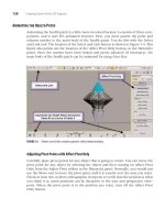
Starting with a Box
Place the first piece of modeling geometry at a key spot in the model. Look for an
area in the model that is central, from which you can build out. In most characters,
that area is the torso. Create a box standard primitive that has only one segment for
length, width, and height, and adjust these values until the box is the same size as
the lower part of the torso. You need to use your Move tool to get this looking right.
Don’t worry about making the box look right for the upper torso yet. Check the side
view to see that the box lines up well.
Making the Modeling Process Easier by Adjusting Properties
Now make the box transparent so you can see the template through it. To make the
box transparent, select it, right-click and go to Properties, See-Through, and click
OK. Convert the box to an Editable Poly. (Select it, right-click, and select Convert to
Editable Poly.) Here it would be nice to see the edges of the box. Make sure Edges
are enabled for selected objects by right-clicking on a viewport name and then
clicking Configuration; check Display Selected with Edged Faces. Note on this screen
another useful option called Use Selection Brackets. Turning off this option gets rid
of the white brackets around selected objects, which can improve clarity in the
viewports. Note in Figure 7.4 that the torso has begun to take shape, and Selection
Brackets are turned off to make seeing the real edges of the model easier.
Adding Symmetry to Speed the Modeling Process
After you have the basic shape of the torso, you can use a Planar Slice to cut the
model into a left and right half. Then delete the left half of the model, select an edge
along the midline, and apply a Symmetry modifier. If you then turn on the Show
End Result toggle, you can continue to work on the Editable Poly while both sides of
the model stay in sync with any changes. For a review of how to use the Symmetry
modifier, see Chapter 2.
Extruding the Arms and Legs
You can extrude and bevel arms and legs from the main torso. Select a face, Extrude
or Bevel, click OK, make an adjustment by scaling or rotating the selected end of the
limb, and repeat. As you go through this cycle, attempt to match the lines of the
template with your model. Work primarily in the front view, but periodically go to
your perspective view and right side view to make sure you are on track with the
template. Figure 7.5 shows this process.
Moving and Adding Vertices as Necessary
Every time you add an extrusion or bevel, double-check your work and adjust ver-
tices as needed to keep the simple form as accurate as possible. You can see in Figure
7.6 that the shape of the shoulder has undergone some modification already; the
172 Creating Game Art for 3D Engines
FIGURE 7.4 Starting with a box.
Chapter 7 Character Modeling 173
rather simple polygons have been adjusted by moving vertices, sometimes one at a
time. It is easier to manage a few vertices at this stage than to wait until there are
more edges and vertices to contend with.
FIGURE 7.5 Build the body with a series of bevels.
FIGURE 7.6 This Slice Plane will be applied only to the selected faces.
This figure also demonstrates that you can cause a slice plane to cut through
only those polygons that are selected. While in Polygon sub-object mode, select the
polygons you want to slice, turn on the Slice Plane button, and click the Slice button.
This slice helps to create a line defining the lower part of the chest without generating
additional cuts on the arms.
Adding Edges with Row, Loop, and Connect
After you have the basic idea of the torso, arms, legs, and feet, it is time to select an
edge on the front of the torso and use Ring to select a ring of edges parallel to your
selected edge. You then click the Connect button to connect the selected edges with
an edge that passes through the middle of all of them. In Figure 7.7, two models are
shown and the menus expanded to illustrate how to prepare the model for the next
phase. In the model at the left, horizontal edges are being selected, which happen to
be lined up in a row on the mesh. You can select one such edge and then click the
Ring button to capture all edges that are similarly ringed around the mesh. You need
to select some of these edges by hand by holding down the Ctrl key and clicking on
them.
174 Creating Game Art for 3D Engines
FIGURE 7.7 Selecting edges by row, and then using Connect.
After you’ve selected all the edges, use the Connect button from the Edit Edges
rollout to cause a connecting edge to pass through the middle of all the selected
edges. Once you’ve done this on the front and back of the model, you also must do
it to the sides of the model, from the groin to the neck. In addition, you need to con-
nect the front and back edges of the arms. This doubles the number of polygons on
the model, but because of the way you built the model, each polygon is effectively
used.
Chapter 7 Character Modeling 175
Adding Volume and Shape to the Mesh
By selecting the newly created edges and moving them slightly away from the model,
you add volume and shape. The idea is to move away from the “box man” and more
toward naturally shaped limbs. The body and limbs that had four edges each now
have eight. In Figure 7.8, the new edges on the front of the legs are selected and
moved slightly forward to suggest roundness.
FIGURE 7.8 Moving edges to add shape and volume to the body.
Using Edge Loops
Edge Loops allow the character mesh to move more believably than standard mod-
eling techniques. In Figure 7.9, six steps take us from our extruded shoulder to a
flow of edges that will look and move more naturally. The upper-left image is the
original starting mesh. The upper-middle mesh has had the vertices at the armpit
area welded together. At the upper right, edges have been cut, connecting the edge
at the top of the bicep to the edge that runs under the armpit. The mesh at the lower
left has had the vertical edges above the bicep removed. A quick way to remove an
edge and any associated vertices is to select the edge and hold down the Ctrl key
while you press the Backspace key. The lower-middle mesh has had an edge added
near the chest to eliminate the five-sided polygon that was formed. At the lower
right, the vertices have been spread out more evenly to create a more uniform and
rounder shoulder shape. Complete this same procedure on the back of the shoulder.
Edge Loops allow you to model more in accordance with how actual musculature is
set up.
Planning for Movement
As the body is going together, what’s going to move? The typical FPS character
doesn’t have facial animations, and it usually doesn’t even have working hands.
There are only upper and lower arm and leg bones, one bone for each hand, one for
each foot, two spine bones, a pelvic bone, a head bone, and possibly a neck bone and
both clavicle bones. These bones have to move in at least a root animation, a run
cycle, a backward run cycle, a sideways run cycle, a jump-fall-land cycle, and a
death sequence. Because you will be putting bones inside this mesh, which will be
responsible for a set of vertices, it is useful even at this early design stage to consider
where the hinge points are for each joint.
If you are going to be using a biped for your skeletal structure, you can create a
test biped next to your character mesh to help you in the planning process. You can
create a biped from the Create panel, under Systems, Biped. Press and drag to create
a biped. Manipulating the biped skeleton is discussed in detail in Chapter 10, “Char-
acter Rigging.” Simply select and hide it when you are not using it, or delete it when
you are through with it. Figure 7.10 shows the nearly complete character mesh
alongside a biped as bone assignments are being considered. A collar has been built
into the neck area of the mesh to hold the head and provide a platform for the hel-
met, which you’ll apply as a separate mesh.
176 Creating Game Art for 3D Engines
FIGURE 7.9 Six steps to creating an Edge Loop.
Chapter 7 Character Modeling 177
Modeling the Hands
One of the best references for modeling a hand is to look at your own hand. You can
pose one hand in position while the other is free to drive 3ds Max. You can model
the hands as a kind of mitten, where you apply the fingers via the texture, or you
can model the fingers separately. If you model the fingers separately, you should
decide at this stage whether you will use separate finger bones to move them or just
model the hands ahead of time so that they are ready to receive the weapon. For the
astronaut, the hands were modeled with the fingers in the proper position for hold-
ing the weapon; finger bones were not used to change their position.
It can be a good idea to model the hands separately from the body of the charac-
ter so that they can receive undivided attention. Often when modeling hands while
the body is attached, you will find yourself constrained by the body mesh being so
close and always in the way or in the background. When the hand is complete, you
can attach it to the rest of the character mesh. A little forethought makes this process
go more smoothly. Try to model the hand so that the number of vertices in the wrist
matches the number of vertices in the wrist of the character body. That way, you
can easily attach the two and weld them together.
FIGURE 7.10 Building the character mesh with the biped bones in mind.
Figure 7.11 shows five stages to creating a hand. To start modeling a hand,
create a box that is 4 × 3 × 1 segments, as shown. In the next stage, you convert the
box to an Editable Poly, and extrude a thumb area. Welding two vertices of this
extrusion gives you the triangular shape. In the third stage, the Editable Poly has
been adjusted a bit so that where the fingers start, the polygons are already rotated
into position. Following that, 2D splines are drawn for each finger. The fingers of the
hands need to be precurved, with thumbs somewhat opposing them, in a loose-
holding position. Similar to the way we created the 2D profile for the barrel of the
weapon, our simple lines serve as a tool to help extrude each finger. If you create
your own finger splines, you have to draw them, one by one, most likely in the right
or left viewport. Then you have to make adjustments, vertex by vertex, in the other
viewports. When the fingers are ready to extrude, select the polygon you want to
extrude, and from the Edit Polygons rollout, click the Setup button for Extrude
Along Spline. In the Extrude Polygons Along Spline dialog box, select the spline you
want the selected polygon to follow, and click OK. See the figure for settings. The
last two stages of the hand are cleanup stages, where vertices are welded and edges
removed to minimize the polygon count. This file is called HandSetup.max, and it’s
available in the Files\Astronaut folder on the companion CD-ROM.
178 Creating Game Art for 3D Engines
ON THE CD
FIGURE 7.11 Modeling a hand from a box in five steps.
Merging and Scaling the Hand to Fit the Body
In this example, a hand was made without concern for units or scaling to demon-
strate how you might scale and use an oversized mesh. When you’re finished
with the hand, name the mesh and save the file. Open your main character file,
select File, File Merge, and locate your own hand file. Alternatively, you can use
Chapter 7 Character Modeling 179
HandSetup.max (again, available on the companion CD-ROM under Files\Astronaut).
You will see a dialog box that allows you to select various elements from the file for
merging. Select Hand5, or whatever your mesh was named, and click OK.
If you merge or import a file that is too big or too small, you can get into Vertex
sub-object mode and scale down the hand with a Uniform Scale until it looks like it
will fit the model of the body. Often when a file is merged, imported, or scaled, mov-
ing the mesh can be tricky, because the Move gizmo is now situated far away from the
model. To correct this, while the hand is selected, activate the Hierarchy panel, and in
the Adjust Pivot rollout, turn on Affect Pivot Only (see Figure 7.12). Move the pivot
for the mesh closer to where the mesh is. A quick way to do this is to click the Center
to Object buton while the Affect Pivot Only button is turned on. Make sure to turn off
Affect Pivot Only before proceeding further. In this screen shot, the hand mesh is
about the right size but still needs to be rotated and placed next to the wrist.
ON THE CD
FIGURE 7.12 Affect Pivot Only allows you to move any object’s pivot point.
In Figure 7.13, the hand mesh is being attached to the rest of the body. Usually
it’s a good idea to leave a little gap between objects, as when you attached the barrel
of the weapon to the main weapon body in Chapter 2. If you have a different num-
ber of vertices on the wrist of the body and on the wrist of the hand, you have to
weld or make additional cuts as necessary so that no vertices are left stray. After
you’ve attached the hand, select its vertices and move it back up where it belongs, so
that the arms are not too long.
Modeling the Head and Face
As with the hands, you can model the head and face separately and then attach
them to the body of the character. You can model the head from a sphere, a box, or
a plane. This example uses plane modeling to create the facial features and then
creates the rest of the head with a geosphere primitive. The face is mostly planar; for
a low-polygon character, you merely need to establish the nose, lips, and eye sockets.
Figure 7.14 shows six stages to modeling the astronaut’s face. In stage 1 at the
upper left, the nose is a 1 × 1 segment plane that has been converted to an Editable
Poly; its edges were copied from the bridge of the nose down to the upper lip. This is
readily accomplished in the side view. The lips are at this stage separate; the upper
lip started as a plane and was converted to an editable poly, and the edges were
copied to the corner of the lip. This is essentially just two quads and one triangle at
this point. The lower lip is similar—just one quad and one triangle. Creating a trian-
gle from a plane is as easy as welding two vertices together. The eye at this stage is
just a 1 × 1 segment plane. When all of these components look good from the front,
check the side view and move them as necessary to conform with the template.
In stage 2, at the upper middle of the screen, the edges of the nose mesh have
been copied down the side of the nose where it meets the plane of the face. The eye
has been cut into eight segments. Although it is impossible to see from the front view,
the corners of the lips have been moved back to reflect the curve of the mouth.
180 Creating Game Art for 3D Engines
FIGURE 7.13 The hand is being attached with a gap to make welding easier.
Chapter 7 Character Modeling 181
In stage 3, at the upper right, the nose polygons have been welded together, and
the eye vertices have been moved to follow the shape of the eye. In this stage, the
eye was also rotated a bit to reflect the curve of the face.
Stage 4, at the lower left, has all the meshes attached to form one mesh. An edge
has been cut in the lower lip to connect with the first vertical edge in the upper lip. Both
upper and lower lip vertices should be moved to give a slightly outward protrusion.
Stages 5 and 6 are made up of connections between polygons. You can select
two edges, and the Bridge feature will connect them. You can also weld together
vertices. You can copy edges to create polygons, or you can create polygons by using
the Create button and clicking three or four vertices in a row. If you do this, always
end on the first vertex you started on; this tells 3ds Max that you are finished select-
ing vertices.
Finishing Off the Head with a Geosphere
To finish the head, you can use a geosphere primitive. The geosphere is superior to
the standard sphere for two reasons. First, the geosphere is more efficient in that it
can cover the same facet detail with fewer overall faces. Second, the regular sphere
FIGURE 7.14 Six stages to creating a low poly face.
(or the lat-long sphere) sacrifices efficiency at the poles, and these poles are difficult
to texture properly with any kind of unwrapping scheme. When you look at these
two factors combined, it makes sense to go with the geosphere every time. The type
of geosphere being used in Figure 7.15 has an Octa Geodesic Base Type, and it has
Smoothing turned off. Use the template to scale and position the geosphere. Attach
the geosphere to the existing facial features mesh, and fill in any holes in the mesh
with copied and welded faces. At the top of Figure 7.15, you see the geosphere being
positioned. At the bottom, the geosphere has been converted to an Editable Poly,
and the lower half of the polygons have been deleted. In the front and side views,
adjust vertices to conform with the template. This character wears headphones
inside of his helmet; a plane, with two segments in each direction, provides a good
start for these. You can adjust vertices and scale and move the entire outer edge to
give the headphones depth.
182 Creating Game Art for 3D Engines
FIGURE 7.15 A geosphere makes a good low poly head shape.
At the far right of Figure 7.15, the finished head has had the geosphere mesh
extended by copying edges. Attach the geosphere mesh, the facial features, and the
headphones, and fill in any gaps by copying edges or creating polygons.
Converting to Editable Mesh and Turning Edges
If your model is still an Editable Poly, convert it to an Editable Mesh. The Editable
Mesh uses triangles, and you will see edges bisecting your four-sided polygons.