CREATING GAME ART FOR 3D ENGINES- P6 pps
Bạn đang xem bản rút gọn của tài liệu. Xem và tải ngay bản đầy đủ của tài liệu tại đây (1.74 MB, 30 trang )
A
NIMATING THE
H
EALTH
P
ATCH
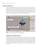
Animating the health patch is a little more involved because it consists of three com-
ponents, and it uses IFL animated textures. First, you must parent the pulse and
exhaust meshes to the main body of the health patch. You do this with the Select
and Link tool. The location of the Select and Link button is shown in Figure 5.4. This
figure also points out the location of the Affect Pivot Only button, in the Hierarchy
panel. Once the meshes have been linked and pivots adjusted (if necessary), the
main body of the health patch can be animated by using Auto Key.
128 Creating Game Art for 3D Engines
FIGURE 5.4 Select and Link creates parent-child relationships.
Adjusting Pivot Points with Affect Pivot Only
Carefully place pivot points for any object that is going to rotate. You can move the
pivot point for any object by selecting the object and then turning on Affect Pivot
Only from the Adjust Pivot rollout in the Hierarchy panel. Normally, you would just
use the Move tool to move the pivot point until it is exactly over the area you want.
Check at least two or three orthographic viewports to verify that the position is what
you think it is; mesh positions can be deceptive in the user and perspective view-
ports. When the pivot point is in the position you want, turn off the Affect Pivot
Only button.
Chapter 5 Animating Game Art 129
Creating Parent-Child Relationships
The Select and Link tool in the Standard toolbar is useful for connecting two objects
so that when one moves, the other does, too. The health patch you are animating in
this chapter requires such a linkage so that when you animate the main body of the
model, the other mesh objects come along with it. Normally, the main mesh or
model is the parent, and other objects that are linked to it are the children. Using a
car as an analogy, the chassis of the car is the parent, and the body, wheels, and en-
gine are the children. If you want to attach a wheel to the chassis, you could say you
are going to parent the wheel to the chassis. Then you could say that the chassis and
the wheel have a parent-child relationship. The Unlink Selection breaks any linkage
to the selected object. If you want to see what types of relationships are in your
scene, click the Select by Name button on the Standard toolbar, and check the
Display Subtree check box at the bottom left side of the dialog box. You can also use
the Schematic View button in the Standard toolbar to graphically see parent-child
relationships throughout the scene.
To parent the pulse and exhaust meshes to the main health patch mesh
(healthpower2), press the Select and Link button, and then click-drag from the child
to the parent. In the case of the health patch, drag from pulse to healthpower2, and
then drag from exhaust to healthpower2.
Because all health patches are rotated by the Torque Game Engine by default,
animate a slight up and down motion to give the impression that the health patch is
hovering over the ground. In this figure, frame 0 has been cloned to frame 80 so that
the animation ends up at the same place it started, creating an effective loop. Notice
here that the time configuration settings have been adjusted so that there are only 80
total frames. Setting the total number of frames to the length of the loop will give you
a better sense of how the loop will look in the game when you play the animation.
Because IFL texture animations are involved, try to coordinate the number of
frames in your hovering animation so that the IFL animations divide into that num-
ber of frames. This way, the IFL animation cycle is not interrupted at the end of the
hovering animation cycle. The health patch and all related files are available in
Files\HealthPatch on the companion CD-ROM.
A
NIMATING THE
W
EAPON
The weapon requires no animation, but there is great potential for weapons anima-
tions. The crossbow weapon in the default starter.fps game is a good example of
what is possible regarding weapons animations. The sequences available are activate,
fire, reload, noammo, and deactivate. These sequences and the instructions for imple-
menting them are discussed in more detail in Chapter 6, “Exporting Game Art.”
The raygun weapon example is not animated, but the railgun is. The railgun
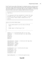
uses three different animations: reload, fire, and noammo. Figure 5.5 shows this in
process. The reload animation comprises frames 0 through 40. The cover on the rail-
gun opens and shuts, making way for the loader, which carries a fresh slug from
ON THE CD
beneath the weapon to the barrel. The loader, which is highlighted in this screen-
shot, had to have its pivot point adjusted before the rotation would look right. The
loader pivot point was moved to where a physical hinge would be. This was done
through the Hierarchy panel, using the Adjust Pivot Only button. The pivot point of
the cover was also adjusted this way to move its hinge point to the very edge where
it meets the body of the barrel. Always move a pivot point in an orthographic view-
port, such as the front or right viewport, so you can be sure of positioning.
130 Creating Game Art for 3D Engines
FIGURE 5.5 The loader, the cover, the projectile, and the muzzle flash are all animated for the
railgun.
Initially, the projectile was parented to the loader, but this presented problems
upon export where the loader and projectile were rotated 90 degrees around Z.
There is likely a solution to this, but for simplicity’s sake, the projectile was keyframed
every two frames so that it tracked the movement of the loader and appears to fol-
low it into the chamber.
The fire animation comprises frames 41 through 49 and involves a visibility
animation. Figure 5.6 shows this process; the
muzzleflash mesh is selected. From the
right-click menu, the Curve Editor is selected. In the Curve Editor, the
muzzleflash
mesh is selected from the objects in the left pane. Click the Tracks drop-down menu,
and select Visibility Track, Add. The new track should appear on the left side of the
Chapter 5 Animating Game Art 131
curve editor. Click on it to select it, and then use the Add Keys button to add
keyframes to this track. In Figure 5.4, a visibility track has been added, and all the
key tangents have been changed to linear with the Set Tangents to Linear button.
This creates crisper transitions from visibility to invisibility. A value of 0 makes an
object invisible, and a value of 1 makes it completely visible. In this figure, you can
also see the keys from the movement of the plane. The visibility keyframes show up
as gray on the Time Slider. If your visibility animation does not seem to be working,
place the Time Slider on a frame where the object should be invisible and then ren-
der out a single frame; this will let you know if visibility is truly working or not.
FIGURE 5.6 Adding and keyframing a visibility track.
Because this mesh is meant to show muzzle flash and it is using an IFL animated
texture material, it is important that the IFL file be in sync with the visibility anima-
tion. You may need to adjust the IFL file contents so that the animated frames work
with the visibility frames. The current IFL starts at frame 0 and lasts 8 total frames,
repeating over and over. At frame 40, the IFL has started its loop again, just in time
for the visibility animation, which starts on frame 41; the muzzle flash images are
shown for two frames each.
The noammo phase of the animation comprises frames 50 through 90. This ani-
mation consists only of a partial movement of the loader mesh. The purpose of this
animation is to inform the player that he is out of ammo. The projectile remains in
the chamber during these keyframes, but because the player cannot see it, there is
no need to move it or make it invisible.
The IFL material for this animation was created in Photoshop using a technique
similar to what was used on the health patch, to generate an Opacity map so that the
outside portions of the flash material are transparent. The rest of the weapon anima-
tion process is to set up Sequence objects for each animation, which is the subject of
Chapter 6. The animated railgun and all related files are available in Files\Railgun
on the companion CD-ROM.
ON THE CD
S
UMMARY
Animation is the illusion of movement. You can set keyframes that dictate what
movement will take place, and you can modify tangencies to speed up that move-
ment or slow it down. You can also animate whether a mesh is seen through visibil-
ity animation, and you can animate textures through IFL animation. After you’ve
keyframed the animation, you need to set up Sequence objects and datablocks so
that the Torque Game Engine understands how to display your animations. That’s
the subject of the next chapter.
132 Creating Game Art for 3D Engines
CHAPTER
6
EXPORTING GAME ART
133
In This Chapter
• Exporting Game Art—Overview
• Setting Up for 3ds Max and Torque
• Previewing Game Art in Torque Show Tool Pro
• Setting Up and Exporting the Simple Shape
• Setting Up and Exporting the Health Patch
• Setting Up and Exporting Ammo
• Setting Up and Exporting Weapons
• Producing Simple Shape Animations
• Troubleshooting
134 Creating Game Art for 3D Engines
E
XPORTING
G
AME
A
RT
—O
VERVIEW
This chapter covers the setup and export for simple shapes, animated simple shapes,
pickups, and weapons. Character creation, setup, and export are covered in Chap-
ters 7 through 12.
Export Components
All art assets require some common components before you can successfully export
them from 3ds Max to the Torque Game Engine. More advanced components such
as level of detail markers, collision meshes, and animation Sequence objects are dis-
cussed later in this chapter, but here’s the list of the basics:
• The model is an Editable Mesh.
• The model has the UVW Map modifier or an Unwrap UVWs modifier applied to it.
• There is a JPG, PNG, or ILF material applied to the model.
• The model is named and has the number 2 appended to it (that is, Health2).
• The model stands at the 0,0,0 origin in the 3ds Max file.
• The model is scaled to fit the game (1 unit = 1 meter), where a human is 2 meters
high.
• Weapons and characters face toward the back.
• There is a marker (or dummy object) named Start01.
• There is a marker (or dummy object) named Base01.
• There is a marker (or dummy object) named Detail2.
• A box named bounds envelops the mesh.
• The Base01 marker is the parent of Start01 and Detail2.
• Start01 is the parent of the main mesh component, such as Health2 or Gun2.
• If other mesh subcomponents exist, they end with the number 2, and the main
mesh component is their parent.
At first glance, this looks like a lot of requirements, but what it boils down to is
that every model you are going to export should be an Editable Mesh that is facing
back, scaled to fit the game, and properly textured. Other than that, there are some
markers, which are really just dummy objects that need to be created in the file, and
there are some hierarchy requirements.
Folder Structure
When you install Torque, a folder is created that can be called Torque, Torque15, or
whatever you choose. The path to the files you will be most concerned about is
Torque15\SDK\example\starter.fps. Starter.fps is the folder that houses the scripts
(\server\scripts) and the shapes (\data\shapes). All scripts discussed in this chapter
are placed in the \server\scripts folder, and all shapes are placed somewhere
within the \data\shapes folder (in a subdirectory that varies with the purpose of the
shape).
Chapter 6 Exporting Game Art 135
Static Shapes Folders
You can place static shapes in any folder you choose underneath \data\shapes. For
example, you can group the oil drum with similar objects in the folder \data\
shapes\barrels. If your static shape does not fit into any of the premade categories,
make a folder; for example, you could have a folder called \data\shapes\machines,
or a folder for animated simple shapes, called \data\shapes\animated.
Health Patches Folder
You can place health patch shape and animation files in \data\shapes\items. If you
are simply changing the definition of the health patch, your health patches will
replace the existing health patches in the mission. You can, of course, add additional
health patches via the Torque Editor. Health patches have datablocks, or script defi-
nitions, that tell them how to operate.
Weapons Folder
Weapons, projectiles, and ammo files should be in \data\shapes\crossbow or some
other weapon folder (such as \data\shapes\raygun). If you make changes to the
folder structure for either health or weapon objects, you need to be sure that your
scripts reflect those new locations. Like health patches, weapons have datablocks
that tell them how to behave.
Bounds Boxes
For Torque to work properly with your files, each model needs a bounds box built
around it. This is a simple box primitive that is big enough to contain the entire
model. Name the bounds box bounds.
Markers, or “Dummy Objects”
Other considerations when exporting game art include objects that help Torque
manage the models. In 3ds Max terminology, these are called dummy objects, but in
Torque parlance, they are referred to as markers. If you are missing a marker or have
improperly named the marker, your export will fail either partially or entirely.
Hierarchy
3ds Max can create parent-child relationships between objects, as discussed in Chap-
ter 5, “Animating Game Art.” The meshes and markers you export must have correct
parent-child relationships or your export will fail.
Pickup Rotation
All pickup items including health patches and ammo rotate by default in the game.
You can turn off the rotation field on any pickups including ammo and health
patches, but the pickup does not stop rotating until you save the mission and relaunch
Torque, entering the same mission. The rotate field is a check box that you see if you
are in the Torque World Editor window and you select a health patch or other
pickup item.
Animations
The primary animations you might want to export are transform animations (where
the mesh is moving or rotating), visibility animations (where the visibility of an object
is controlled by keyframes), and IFL animations. All animations require Sequence
objects and datablocks. If you want to export a transform or IFL animation with a
simple shape or a pickup, you need to create a Sequence object for it. The datablock
references the Sequence object by name.
S
ETTING
U
PFOR
3
DS
M
AX AND
T
ORQUE
This preliminary setup prepares 3ds Max to export data by installing the DTS ex-
porter, and it prepares the Torque Game Engine to import data by editing a script
file. Entering the Torque Game Engine editor, saving missions, dealing with scripts,
and working with the console window are discussed in this section.
Installing the DTS Exporter
The standard Torque DTS exporter is a plug-in for 3ds Max. There is one for 3ds Max
4 and 5, another for 3ds Max 6, 7, 8, and one for 3ds Max 9. They are all named
Max2dtsExporter.dle. It is up to you to keep them straight on your machine; putting
them into separate directories is a good idea. Place the file that is appropriate for
your version of 3ds Max in the plugins folder of your installation of 3ds Max. Then
restart 3ds Max so the software can see the plug-in. This exporter is available in the
Software\TorqueDTSExporters folder on the companion CD-ROM.
The Dark Industries DTS exporter is a completely separate exporter. It is an EXE
install that comes with a PDF guide. It is called MaxDTSexporter_DC3.exe. It runs an in-
stall and modifies your standard toolbar; the next time you launch 3ds Max, you will
have an install. It places a DLE file called Max2DTSExporterPlus.dle in your plugins
folder. This program shows up in your Add/Remove Programs list as Max 7 DTS Exporter
1.3. This exporter should work for 3ds Max versions 6, 7, and 8. A newer, unpack-
aged version of this exporter (as well source code) is available by searching the
GarageGames Web site (). MaxDTSexporter_DC3.exe
is available in the Software\DarkIndustriesDTSExporter folder on the companion
CD-ROM.
136 Creating Game Art for 3D Engines
ON THE CD
ON THE CD
Chapter 6 Exporting Game Art 137
You should not install both exporters simultaneously. If both exporters are
installed, 3ds Max uses whichever one it wants, and you don’t get consistent results.
Therefore, install only one; if this is your first time, though, it is better to stick with
the standard exporter until you have more experience. If you want to try the Dark
Industries version, first remove the standard exporter DLE from your plugins folder.
Remove in this case really means removing the file from the folder; renaming the
file may not be enough.
Setting Up Torque for First Person Shooter
You must make one script change so that Torque launches in First Person Shooter,
or FPS, mode, and you can have easy access to the Torque Editor. The main.cs file is
located in the SDK\example folder. Open this file and set the $defaultGame variable to
“starter.fps”, as shown here:
$defaultGame = “starter.fps”;
Try to back up any scripts you edit. You can edit Torque Game Engine script files
with any text editor, but for the longer scripts, Codeweaver is a good solution.
Codeweaver gives you colored code entries and numbered lines, as well as many
other benefits. At the time of this printing, this product is available free at http://
www.torquedev.com. You must register to use this product.
Deleting CS.DSO Files So That CS Files Will Be Read
The scripts you will be editing are plain ASCII, or human-readable files. All of the
script files end with CS, and when they are compiled for performance, they become
CS.DSO files. When you have made a change to a CS file, sometimes it will not be
run unless you first delete the corresponding CS.DSO file. For example, one of
the files you will be editing is called health.cs. After you have edited this file, delete
health.cs.dso, because this old version may actually take precedence the next time
the engine runs, which can cause you confusion and frustration. If you are editing
script files, delete all of the CS.DSO files in the server/scripts folder to avoid this
issue.
Entering the Torque Editor
You can enter the Torque Editor by launching Torque. If your installation folder is
called Torque15, look in the Torque15\SDK\example folder for torqueDemo.exe, and
double-click it to launch. Start the Stronghold mission as usual, and then press F11
to enter the Torque Editor. From here, you can access several different windows that
will allow you to change the game environment. Under the Window drop-down
menu, you can use the World Editor Inspector (F3) to inspect and modify existing
game objects, and use the World Editor Creator (F4) to insert new objects into the
game.
Saving and Renaming Missions
Most of the assets discussed in this chapter must be placed in the mission by hand.
At some point, you must save the mission if you want the object to be there the next
time you come into the game. To save a mission name, first make sure you are in the
World Editor Inspector, as shown in Figure 6.1. Change the mission name in two
places. Under SimGroup, MissionGroup, click on ScriptObject, MissionInfo. Here you
can change the mission name and description. Then, from the File drop-down
menu, change Save Mission As to the same name. The Script Object, MissionInfo
value changes the name you see in the missions list when you start Torque; Save
Mission As changes the actual name of the mission in the \data\missions folder. See
Figure 6.1.
138 Creating Game Art for 3D Engines
FIGURE 6.1 Change the mission name in two places.
Checking the Torque Console Window
When one of your models is not showing up, or if an animation is not running, you
can often find clues to the problem by consulting the console window. You can
Chapter 6 Exporting Game Art 139
launch this window from the Torque Editor by pressing the tilde (~) key that is located
below the Esc key on your keyboard.
P
REVIEWING
G
AME
A
RT IN
T
ORQUE
S
HOW
T
OOL
P
RO
The Torque Show Tool Pro is an incredibly useful tool for evaluating your game
assets. In seconds, you can figure out if the mesh and textures are exporting prop-
erly, rather than going through the tedium of launching a game every time you
need to run a test. With this tool, you can analyze animations, slow them down,
study node movement, see various levels of detail, change lighting, see shaded and
wireframe images, and more. Full zoom, pan, and 3D rotation is available via the
mouse buttons. To use the Torque Show Tool Pro, you simply set up a project folder
where you can find the DTS object and click Load DTS. To load animations for the
DTS shape, click Load DSQ. In Figure 6.2, the Torque Show Tool Pro is being used
to check the texture and animation of the health patch. The ambient animation is
current, and the Play button is on at the bottom of the image.
FIGURE 6.2 The Torque Show Tool Pro is great for previewing game art.
S
ETTING
U
PAND
E
XPORTING THE
S
IMPLE
S
HAPE
We will use the oil drum to demonstrate the setup and export of a simple shape. To
keep this process as clear and simple as possible, we will export the oil drum without
levels of detail or a collision mesh the first time through. Later in this section, we’ll
add levels of detail and collision meshes.
Accessing the DTS Export Utilities
Figure 6.3 shows that after you’ve placed the DTS export plug-in in the 3dsMax\
plugins folder, you can access the utility via the Utility panel by clicking on More.
Select DTS Export Utility and click OK. The Utilities rollout should then appear at
the bottom of your panel. This figure also shows the options available on the DTS
Export menu. For any art assets other than character animations, you can simply
click Whole Shape from the Utilities rollout to export the DTS shape.
140 Creating Game Art for 3D Engines
FIGURE 6.3 Accessing the DTS Exporter Utility.
Setting Up the Hierarchy of a Simple Oil Drum
Figure 6.4 shows how simple a shape can be at export time. Clicking the Schematic
View button on the Standard toolbar launches the Schematic View dialog box. The
view shows the three markers (or dummy objects): Base01, Start01, and Detail2.
Chapter 6 Exporting Game Art 141
The mesh is called OilDrum2 and is a child of Start01. The bounds object, in green in
the screen shot, is not part of the hierarchy. You can achieve this hierarchy by nam-
ing your model OilDrum2 and clicking the Embed Shape button on the DTS Exporter
menu. If you want to create the markers yourself, create three dummy objects, place
them at 0,0,0, and follow the naming and parenting conventions in this figure.
FIGURE 6.4 The components and hierarchy necessary for a super-simple export.
Exporting the Simple Shape
Export the oil drum by clicking the Whole Shape button on the DTS Export menu.
When prompted, select an export path that is the same as that of the 3ds Max file
you are working on, or you may have problems exporting. No matter what folder
you use for exporting, ultimately you want the DTS file and any related textures to
be placed in
\data\shapes, in the appropriate folder. Because the oil drum is similar
to a barrel, you can use
\data\shapes\barrels. If your simple shape was a plant, for
instance, you could create the folder \data\shapes\plants and put the DTS shape
and any textures there.
Inserting the Simple Shape into the Game
In Figure 6.5, the FPS Stronghold Mission has been launched. F11 is pressed to enter
the Torque Editor. By default, the current window is the World Editor Inspector.
This editing window is for inspecting and modifying objects that already exist in the
mission. To add a new object, you need to go to the Window drop-down menu and
select World Editor Creator, as shown in Figure 6.5.
At the right are two panels. The upper panel, which has been sized down some-
what, is for accessing objects already in the mission and for setting up groups to put
your new objects into (which is optional). The lower panel is where you access the
folder structure to insert new instances of objects. In this screen shot, you can see
the Static Shapes category, under Starter.fps, Data, Shapes, Barrels, and finally the
objective, OilDrum3. By clicking on OilDrum3, you automatically insert that object in
the scene, roughly in front of where you are currently positioned in the game. As
soon as the object lands in the game, it has positional arrows you can click-drag to
move the object as necessary.
In Figure 6.6, the oil drum has been moved and scaled. Notice that the current
window is the World Editor Inspector. The yellow box around the oil drum tells us
that it has either just been added or it has been selected. On the right, you can see
the properties that are editable for the selected object; 3 3 3 has been entered to
scale the object up uniformly from the default of 1 1 1. If you find that your assets
are too small compared to the rest of the game world, it is better to scale them up in
sub-object mode in 3ds Max, but Torque is a good place to get a feel for what adjust-
ments you need to make.
142 Creating Game Art for 3D Engines
FIGURE 6.5 Inserting a static shape into the game with the Torque Editor.
Chapter 6 Exporting Game Art 143
After you’ve saved the mission, the process of exporting the asset and placing it
in the game environment is complete. In the next section, you apply levels of detail
to the oil drum so that the engine can work more efficiently.
Applying Levels of Detail
The levels of detail, or LOD, capability in Torque allows you to set up multiple versions
of any given mesh, each with different complexity, and it allows Torque to pick which
version to display at any given time, based on how close the player is to the object. You
can apply the Multires modifier in 3ds Max to any Editable Mesh and use it to decrease
the complexity of the geometry. To use the Multires modifier, click the Generate but-
ton and then set the Vertex Percent value to a smaller number.
Here’s how it works: Start with the shape the way you want it to appear when
the player is pretty close to it in the game. Let’s call this high-detail version shape128,
because it is what the player sees if the image in question is 128 pixels or higher in
the game. Now, make a cloned copy of this same shape, but decrease the number of
FIGURE 6.6 Modifying the static shape inside of Torque.
polygons by about half, and call it shape64. This is the version of the shape the player
sees if the image in the game is between 64 and 128 pixels high. The final mesh is
called shape2; you can simplify it further, because it appears to the player only when
the player is far away from it, and it takes up between 2 and 64 pixels in the game.
For each of these meshes—shape128, shape64, and shape2—a detail marker is re-
quired: detail128, detail64, and detail2.
All of these detail dummies should be children of base01. Of all the shape files,
only shape128 (the highest resolution one) should be a child of start01. Shape64 and
shape2 have no parents or children.
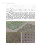
If you want to convert the oil drum model to one that uses different levels of
detail, start by deleting all the markers we have now. All that should be in the scene
is OilDrum2 and a box named bounds. Apply a Multires modifier to OilDrum2. Use Edit,
Clone to clone two copies of OilDrum2. Call them OilDrum64 and OilDrum128. Use the
Select by Name tool on the Standard toolbar to select OilDrum64; turn on the Gener-
ate button at the bottom of the Multires Parameters rollout, and change the Vertex
Percent value to 50%. Select OilDrum2 the same way, and set its Vertex Percent to
25%. Then select OilDrum128, and click the Embed Shape button on the DTS Export
Utility menu. This process creates the hierarchy and markers shown in Figure 6.7.
144 Creating Game Art for 3D Engines
FIGURE 6.7 Components and hierarchy necessary to have three different levels of detail.
Because a game engine must render objects dynamically in real-time, game
speed is greatly affected if too many polygons are being rendered at any given time.
By setting up LOD for all shapes that have any complexity, you can improve the
performance of the game and only render the complex geometry when necessary.
When the player is looking at a complex object, other objects in the far distance are
at their simplest detail setting.
Chapter 6 Exporting Game Art 145
Causing Collisions
If you want this object to be capable of causing a collision if a player bumps into it,
you must create an additional shape that encloses the object as tightly as possible
without becoming concave. In other words, you must use a box or an Editable Mesh
that as closely as possible matches the geometry of the shape, yet is completely con-
vex. A simple sphere or box is a good example of a convex shape. A star is another
example of a convex shape, because at least a portion of its geometry self-intersects.
A further requirement is that the collision mesh should not exceed the perimeter of
the bounds box. The collision mesh must be called Col-1, and you must have a marker
called Collision-1. The hierarchy in a file utilizing collisions is that the collision
marker (Collision-1) is a child of base01, and the actual collision mesh (Col-1) is a
child of Start01. You can clone one of the detail markers and name the new copy
Collision-1, or you can create a dummy object and parent it to the base01 marker.
Figure 6.8 shows the updated hierarchy for the oil drum with collision objects. This
file (OilDrumTexturedcol.max) is available in Files\OilDrum on the companion CD-ROM.
ON THE CD
FIGURE 6.8 Components necessary for levels of detail and collisions.
With all these meshes for LOD and collision residing in the same space, take care
when you apply materials—particularly materials that have transparency. With so
many meshes in one place, it is easy to apply a material to the wrong mesh. Hiding
any meshes you are not actually working on helps keep things clear. When in
doubt, use the Select by Name tool in 3ds Max to select objects.
S
ETTING
U
PAND
E
XPORTING THE
H
EALTH
P
ATCH
The health patch has multiple LOD meshes and a collision mesh and utilizes both
transform animation and IFL animation. The hierarchy necessary for this shape is
shown in Figure 6.9. The health patch is similar to the oil drum in respect to the base
and start markers, the bounds box, and a detail marker. Where the health patch differs
is in the linked meshes and the animation Sequence object (which will be discussed
shortly). As is evident from this figure, the two meshes (pulse and exhaust) are
parented to healthpower2. This linkage is enough to cause them to be included in the
export process. They do not require their own detail markers.
146 Creating Game Art for 3D Engines
FIGURE 6.9 The health patch hierarchy;
exhaust and pulse are children of healthpower2.
Colliding with Health Objects
Health patches need a collision mesh, because it is only when the player collides
with a health patch that the patch can be activated. Do not expect health patches to
stop your player the way a tree or a regular static object does when you collide with
it. The collision property of a health item engages only if a player who hits it is low
on health. Otherwise, you can run right through them. Even when your player is
low on health and runs into a health patch, the collision only triggers an increase in
health, at which time the health patch deletes itself from the game.
Embedding Sequence Objects
If the art has any animation, even if it is just IFL material animation, your DTS file
needs to have a Sequence object embedded within it. The Sequence object, applied
in 3ds Max, tells the Torque engine what frame the animation starts on and where
it ends, and it passes along other settings. The Sequence object must be referenced in
your Curve Editor for the start and end frames. This means you have to add keys to
the Sequence object in the Curve Editor. Also, you need to select the Sequence
object and go to the Modify panel and adjust advanced export settings, to include
IFL or any other animation data you want to export.
Don’t worry about exporting a sequence file separately unless you are doing a
character run cycle animation or something similar and you want to keep your dif-
ferent sequences separate. Otherwise, the DTS shape has the animation sequence
Chapter 6 Exporting Game Art 147
bundled into it. You can find the Sequence object in 3ds Max in the Create panel under
Helpers, General DTS Objects (see Figure 6.10). Sequence is the only option avail-
able in this menu; the Sequence object is drawn similar to the way a dummy object
is drawn, by doing a click-drag. By selecting and right-clicking on the Sequence
object, you can choose Curve Editor from the right-click menu and locate the
Sequence object Start and End Track.
FIGURE 6.10 Creating the Sequence object, and adding the Begin/End keys in the Curve Editor.
If your Sequence object is not showing up in the Curve Editor, you may need to
adjust the Curve Editor Filters; click Display, Filters, Show Group, Objects. Some of the
sample files that come with the Torque Game Engine use an On/Off controller for
the Begin/End of the Sequence object; at least in release 8, the default controller type
for the Sequence object is Boolean. Either type of controller should work, because
they behave the same. Boolean is probably easier to use; if you decide to use the
On/Off controller, add your keyframes from the Dope Sheet (Modes, Dope Sheet),
because you cannot add keyframes to an On/Off controller from the Curve Editor.
When a Sequence object is being used for any kind of animation, check its para-
meters before exporting the DTS. In Figure 6.11, the Sequence object has been se-
lected and the Modify panel reflects the options available in the General, Ground
Transform, and Export Control rollouts. Normally, you use a cyclic sequence (a re-
peating loop), and Ground Transform is unchecked. In Export Control, check any
boxes that apply. Some boxes, such as the Decal Animation check boxes, are based
on earlier engine requirements and are no longer used.
On the left side of this prepared image, you can see a wireframe image of what
is being exported; the various markers are in green at the bottom of the health
patch, and the Sequence object is the white box at the upper right (white because it
is selected). The blue box around the health patch is the collision mesh, and the
yellow box is the bounds box. When working with shaded images, you usually need
to select any boxes that are in the way and use the right-click menu to hide selected
objects. Hiding the bounds box or collision meshes does not prevent them from being
exported.
Inserting the Health Patch into the Mission
You can insert the health patch into a mission the same way you inserted the simple
object, except that health patches and ammo are found under the \data\shapes
folder. Make sure you are in the World Editor Creator window when inserting
shapes, and then select the World Editor Inspector window if you want to edit the
size or some other characteristics of the shape (see Figure 6.12).
Scripting Health Patch Animation
A health patch performs no special animations, other than the standard pickup rota-
tions, without activating its Sequence object. The following code is placed in the file
health.cs, which is located in the \server\scripts folder. Health.cs already has a
function called onCollision; in the code that follows, we are adding a function called
onAdd, which is executed when the health patch is added to the world. Using this
code assumes that you have a Sequence object named ambient in the 3ds Max file,
and that the beginning and end keys are set for the start and end of the animation in
148 Creating Game Art for 3D Engines
FIGURE 6.11 The export settings for the Sequence object in the Modify panel.
Chapter 6 Exporting Game Art 149
the Curve Editor. Be sure to delete health.cs.dso from the same folder to ensure
that health.cs is read and compiled the next time you start Torque.
function HealthPatch::onAdd(%this,%obj)
{
%obj.playThread(0,”ambient”);
}
Analyzing the Characteristics of a Health Patch
Health patches have the same requirements as simple shapes, but they also need a
datablock that tells Torque they are a health patch and you have to place them in the
correct folder. Fortunately, the datablock is already created for you in the standard
starter.fps install. Because pickups use a datablock, you can animate them. The
FIGURE 6.12 Inserting the health patch via the World Editor Creator window.
health patch datablock is called health.cs, which is located in starter.fps\server\
scripts. The following code shows an excerpt from health.cs, which describes what
to name the health patch and where to put it.
datablock ItemData(HealthPatch)
{
// Mission editor category, this datablock will show up in the
// specified category under the “shapes” root category.
category = “Health”;
// Basic Item properties
shapeFile = “~/data/shapes/items/healthPatch.dts”;
The tilde in the last line is a way of saying that the shapeFile is located in
the starter.fps folder, under \data\shapes\items. If you move the original
healthpatch.dts to a storage folder (or if you rename it), you can replace it with
your own design. Using the name healthpatch.dts saves you script editing.
The health patch data files are available in Scripts\Data\Shapes\Items, on the
companion CD-ROM. Health.cs is available in Scripts\Server\Scripts on the com-
panion CD-ROM.
S
ETTING
U
PAND
E
XPORTING
A
MMO
The hierarchy for ammo is shown in Figure 6.13. At a minimum, you need the same
markers and meshes as you would for a simple shape. The collision mesh and markers
are mandatory because that is how the engine tells that you have reached this pickup.
You have to place this object inside the game the same way you placed the health
patch inside the game, except that ammo will have its own folder. The ammo, like the
health patch, automatically rotates when it is inside the game. Place the ammo.dts
shape and the texture associated with this file in whatever folder you have designated
for the weapon. For example, the crossbow ammo.dts is kept in data\shapes\crossbow.
The ammo for the raygun is kept in the new folder \data\shapes\raygun, along with
the actual weapon and associated files. To place the ammo in the mission, use the
same technique that has been described for simple shapes and pickups. As long as the
ammo.dts file is in the right folder, and the ammo-related scripts have been properly
edited, the ammo should appear under shapes\ammo.
The ammo shape has a plane that is designated as a billboard object. The way the
billboard is used in this shape is to create a glow effect. For any shape that has a bill-
board, you need a mesh that has BB:: in the prefix, as in Figure 6.14. All billboard
objects must start with BB::. Other requirements necessary for the billboard to ap-
pear in the game are covered in Chapter 4, “Texturing Game Art.” The ammo shape
and its associated files are available on the companion CD-ROM.
150 Creating Game Art for 3D Engines
ON THE CD
ON THE CD
Chapter 6 Exporting Game Art 151
S
ETTING
U
PAND
E
XPORTING
W
EAPONS
Setup and export of weapons is similar to that of health patches, except some addi-
tional files work with weapons. The best way to develop your own weapon is to start
with an established weapon like the crossbow and copy the contents of that folder to
your own folder, replacing the shapes as you go. That way you have all the basic
files you need in one place. If your weapon shape is going to have animations, you
need Sequence objects for each animation. Finally, you need to alter the scripts to
ensure that Torque understands where to find the weapon files.
FIGURE 6.13 The simple ammo hierarchy.
FIGURE 6.14 The hierarchy for ammo with a billboard.
Weapons Components
The typical weapon is similar to the typical health patch; it requires markers,
a bounds box, a datablock, and a particular location. A weapon also has a MountPoint
marker that tells the weapon where to mount to the character and a MuzzlePoint
marker that tells the projectile where to launch from. A weapon also needs a
projectile.dts shape; this projectile is what is fired from the weapon.
The Projectile
Figure 6.15 shows the simple hierarchy necessary to create a projectile, along with a
wireframe image. This projectile shape is a cylinder, although your projectile can be
any shape you want. The projectile shape is available on the companion CD-ROM.
152 Creating Game Art for 3D Engines
ON THE CD
FIGURE 6.15 A projectile hierarchy.
A Simple Weapon Hierarchy
Figure 6.16 shows the hierarchy of a weapon with no animations. This example is
taken from the raygun.
Preparing and Exporting Weapon Animations
For every weapon animation, including any IFL texture animations, you need a
Sequence object. Figure 6.17 shows the relatively complex hierarchy necessary to
support animations. Reload, fire, and noammo are Sequence objects that define the
start and end points of animations.