Wireless địa phương vòng - lý thuyết và ứng dụng P1 ppt
Bạn đang xem bản rút gọn của tài liệu. Xem và tải ngay bản đầy đủ của tài liệu tại đây (260.94 KB, 33 trang )
Part I
Theoretical Aspects
Wireless Local Loops: Theory and Applications, Peter Stavroulakis
Copyright # 2001 John Wiley & Sons Ltd
ISBNs: 0±471±49846±7 (Hardback); 0±470±84187±7 (Electronic)
1
Introduction to WLL: Digital
Service Technologies
Ioannis S. Barbounakis and Peter Stavroulakis
1.1 Background
During the last few years, the telecommunications sector has progressed remarkably
thanks to the numerous technological advances occurring in the field. The demand for
communication services has also increased explosively worldwide creating or imposing
tougher capacity requirements on the telecommunication infrastructure. In developing
regions, this demand reflects the great need for the basic telephone services, i.e. the Plain
Old Telephone Service (POTS), whereas in developed regions it applies to high-rate data
and multimedia services at home and/or office. In addition to these recently established
conditions, the liberalization of the telecommunication sector, taking place in our days,
has unexceptionably driven innovation on the telecommunication infrastructure. It is only
the local loop segment that has left unchanged despite all these technological innovations.
Lately, however, it has attracted the attention of telecommunication carriers since it
proves to be the bottleneck in their network expansion. Consequently, more efficient
transmission techniques (ISDN, DSL) improving the capacity of the copper wires or
alternative physical media such as fibre, coaxial cable and wireless terrestrial or satellite
links have started to be deployed more and more.
It is not only the rapid penetration, which is necessary in developing regions, but also
the need for higher capacity in developed regions that have made other physical media
apart from our common copper wiring viable solutions in the local loop arena. Today's
copper wiring is mostly limited to a maximum distance of 5 km between the subscriber
and the local exchange, with the average being in the region of 2 km. This class of
transmission channels is sufficient in providing POTS and data through voice-band
modems. Moreover, it has reached its upper limits and only thanks to digital techniques
such as Integrated Services Digital Network (ISDN) and Digital Subscriber Line (DSL), it
keeps a high competitiveness. ISDN has been the first digital transmission technology to
work over existing copper lines offering voice, data and low-resolution video simultan-
eously. DSL technology has followed offering data and voice integration with a higher
efficiency than ISDN but at the cost of farther limitations. DSL lines must be clean
copper from the local exchange to the customer premises. The service also degrades
dramatically as the distance from the local exchange increases, limiting bandwidth avail-
able to customers or preventing access to more rural users. Asymmetric DSL is the
3
Wireless Local Loops: Theory and Applications, Peter Stavroulakis
Copyright # 2001 John Wiley & Sons Ltd
ISBNs: 0±471±49846±7 (Hardback); 0±470±84187±7 (Electronic)
technology favoured by many operators or Internet Service and Multimedia Content Pro-
viders. Downstream speeds typically are much faster than the upstream speeds. Symmetric
DSL is more popular with local exchange carriers (LECs), which locally compete with
incumbent operators for customers. Connection speeds are the same in both directions.
Optical fibre has been utilized in the trunk network as a more efficient and cost-
effective solution for many years now. In many countries it has also replaced copper in
the distribution network. However, when considering the local loop the undertaking
becomes too risky mainly due to the high cost involved in such a large-scale deployment.
Cable television has become a reality to many people worldwide for more than 20 years
now. When the customer base grew up to a significant level, cable operators thought of
providing telephony services through a new type of bidirectional cable modem. Although
the coaxial cable is a high-bandwidth channel, the fact that only selected areas of the
world and selected populations within these areas would be interested in services other
than CATV make this medium cost-ineffective for a local loop option.
Another solution, which adopts radio as the transmission medium, in the local loop is
the wireless local loop (WLL). WLL is often called the radio local loop (RLL) or the fixed
wireless access (FWA). Since WLL is a kind of radio system, it is natural that its
technology has been affected by wireless mobile communication technologies. In fact, as
will be shown later, most WLL systems have been developed according to the standards
(or their variants) for second-generation cellular and cordless systems. However, until
now that third-generation cellular systems, i.e. Universal Mobile Telecommunication Sys-
tems (UMTS) start to be deployed, WLL systems were at a disadvantage compared to
their wireline counterparts in terms of voice quality and data rates supported. In general,
almost all of cellular/cordless systems or multiple access techniques can be used for
narrowband WLL. However, it is also true that there exist some technologies or systems
that have comparative advantages in a certain WLL environment.
Many manufacturers and TV broadcasters have been promoting the idea of deploying
terrestrial microwave distribution systems mainly for television provision as broadband
wireless systems. The philosophy behind such systems is to provide a reverse link as well.
Services like Video on Demand and wideband Internet connections are among the first to
be offered. At the assigned microwave frequencies, high propagation losses and weather
effects such as heavy rain play an important role in the power budget design of the system
probably making it a less favoured solution for wireless local loop access in rural and
sparsely populated areas.
Last but not least, there are the satellites, which support network access to all sub-
scribers rather than only the fixed ones. Despite the long delays and the high equipment
cost, they will play an important role in providing global network access to rural areas not
available through other means or small communities with a minimum degree of mobility.
In this chapter, we attempt an overview of several WLL digital service technologies,
which have been developed during the last years. We classify them according to their
range, capacity and air-interface specifications standardized or not. Through their pre-
sentation, our aim is to conclude on what WLL is able to offer to the developing and
developed world now and in the foreseeable future.
Section 1.2 outlines the advantages of efficient WLL systems in developing and de-
veloped regions. Section 1.3 focuses on the requirements that WLL has to meet in order to
compete in the local loop arena. Section 1.4 presents a generic WLL system architecture
and focuses on the technological breakthroughs in the wireless transceiver architecture on
a per functional block basis. Section 1.5 describes the digital service technologies, which
4 Introduction to WLL: Digital Service Technologies
are in the phase of deployment or trial worldwide. Section 1.6 compares all WLL
candidate technologies in terms of range, quality, service capability, etc. Finally, conclud-
ing remarks are derived in Section 1.7. For completion purposes, two appendices are
given. Appendix A clarifies the differences of cellular technologies being deployed with
fixed instead of mobile subscribers. Appendix B constitutes an answer to the question
`which multiple access format is more efficient: CDMA or TDMA?'.
1.2 Advantages of Wireless Systems
Wireless systems are justified as a local loop solution because of the cost-effectiveness and/
or limitations of other technologies such as copper, coaxial cable and fibre. However,
there has not been established any standard for WLL yet. WLL systems, which are
currently deployed, are based on a wide range of radio technologies including satellite,
cellular/cordless and many proprietary narrowband or broadband technologies depending
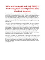
on the desired subscriber density as well as on the coverage area under service (see Figure
1.1).
WLL has many advantages from the viewpoints of the service providers and subscribers
[1±7]:
Fast Deployment WLL systems can be deployed in weeks or months as compared to the
months or years needed for the deployment of copper wire systems. Faster deployment
can mean sooner realization of revenues and reduced time to payback of the deployment
investment. Even with higher costs per subscriber that may be associated with the WLL
terminal and base station equipment, the faster rate of deployment can permit a higher
return of investment. The rapid rate of deployment can also yield first-mover advantage
with respect to competitive services, can accelerate the pace of regional economic growth,
and can provide substantive progress in the development of needed infrastructure.
Low Construction Cost The deployment of WLL technology involves considerably less
heavy construction than does the laying of copper lines. The lower construction costs may
be more than offset by the additional equipment costs associated with WLL technology,
but in urban areas, especially, there may be considerable value in avoiding the disruption
that the wide-scale deployment of copper lines entails.
Subscriber
Density
WLL cell radius
3 km 30 km
Urban
Suburban
Rural
Cellular
Cordless
Satellite
proprietary Narrowband
LMDS
Figure 1.1 WLL coverage using different technologies
Advantages of Wireless Systems 5
Low Operations and Maintenance Cost The operations and maintenance are easy and the
average maintenance time per subscriber per year is shorter 3 to 4 times than their wireline
competitors.
Customer Connection Cost It is low, so overall `cost per customer' is significantly lower
than wireline or cellular systems.
Lower Network Extension costs Once the WLL infrastructureÐthe network of base
stations and the interface to the telephone networkÐis in place, each incremental
subscriber can be installed at very little cost. WLL systems that are designed to be
modular and scaleable can furthermore allow the pace of network deployment to
closely match demand, minimizing the costs associated with the underutilized plant.
Such systems are flexible enough to meet uncertain levels of penetration and rates of
growth.
High Handwidth Services Provision Using advanced digital radio technologies, WLL can
provide a variety of data services and multimedia services as well as voice.
High System Capacity Among radio systems, WLL enjoys the merits of fixed system:
using high-gain directional antennas, the interference decreases. This reduces the fre-
quency re-use distance, increases the possible number of sectors in a sectored cell, and
increases, in turn, the system capacity (see Appendix A).
1.3 WLL Service Requirements
The services offered depend strongly on the customer segment. These will in turn impact
the bandwidth required to deliver the service and hence the supporting technology, since
not all can deliver the high rates required for advanced services.
The emergence of ADSL, cable network upgrades for data services and develop-
ments in 3
rd
-Generation mobile all impact the WLL service in a competitive environ-
ment. They drive the minimum data rate needed for a fixed wireless solution to remain
competitive in the residential segment. With the introduction of broadband wireless
technologies, data rates of more than l0 Mbit/s are now possible, accommodating
bandwidth intensive applications such as video-on-demand or LAN interconnect. The
broadband wireless systems being deployed worldwide today are targeting mainly
multitenant business buildings with E1/T1 services for aggregated telephony or IP
traffic.
A summary of service needs for different customer types is shown in Table 1.1. In all
cases, if WLL systems have to be competitive in service provision to alternative suppliers,
they have to satisfy the following requirements that vary with respect to the servicing area,
the target group of potential customers and the kind of services offered:
Communications Quality Since a WLL system serves as an access line for fixed telephone
sets, it must provide the same level of quality as conventional telephone systems with
respect to such aspects as speech quality, grade of service (GOS), connection delay and
speech delay.
6 Introduction to WLL: Digital Service Technologies
Table 1.1 Service needs per customer type
Customer\Service Basic
Telephony
Internet
data/fax
BRA
ISDN
n  64=56
Kbps
n E1/T1
PRA ISDN
LAN
ATM
MPEG2 IN
functions
Very large business &&&& && &
Large business &&&& && &
Medium business &&&& DD &
Small Business &&&& &
SOHO &&&& D
High spending resident &&&D &
Med spending resident &&& D
Low spending resident & D
& : means full use D : means partial use
Secure Transmission WLL must be secure to give the customer confidence that conver-
sation remains confidential. The system should also include authentication to prevent
fraudulent use.
ISDN Support The system should support integrated services digital network (ISDN)
when appropriate to provide voice and data service.
Easy Environment Adaptation The system should be capable of small-cell or large-cell
operation to serve dense urban or rural areas respectively.
Absence of Interference with Other Wireless Systems A WLL system must not cause any
interference with the operation of existing systems, such as microwave communications
and broadcasting systems.
High Traffic Volume One characteristic of a WLL system is that it must support a larger
traffic volume per subscriber than mobile or even wireline communications systems.
High Capacity and Large Coverage The maximum system range and base station cap-
acity should be large to make the `cost per subscriber' as low as possible and minimize the
entry cost for an operator.
A first assessment of these requirements shows that from the subscriber's perspective
service quality and confidentiality as well as bandwidth availability are of great import-
ance. From the perspective of the system operators, the high priority requirements of
WLL systems are high-capacity and large coverage. Technically, it is a big challenge to
meet these two contradicting sets of requirements and still lower the cost of deploying a
WLL system and utilize the spectrum efficiently. Since the three key driversÐvoice
quality, coverage, and capacityÐare always competing among themselves, one may
have to determine an acceptable voice quality level first, and then choose a WLL
technology that can provide high-capacity and large coverage.
WLL Service Requirements 7
1.3.1 Developing Regions
In many developing regions, the infrastructures for basic telephone services are still
insufficient. Accordingly, a lot of population in these areas has not been served with
even plain telephony service. For these areas, the requirements of WLL services can be
summarized in the following:
. In terms of service coverage, a wide area should be covered within relatively short
period.
. Especially, for the regions with dense population, a high-capacity system is indispensable.
Here, the capacity is the available number of voice channels for a given bandwidth.
. On the other hand, there may exist wide areas with sparse population. For these service
areas, if a small population with low traffic load resides near by, a centralized FSU
serving more than one subscriber can be a solution.
. The service fee per subscriber must be low so as to offer the universal service. For this,
a high-capacity system is again needed and the cost of system implementation and
operation should be low.
. The system should be implemented rapidly so that the services might be launched
quickly.
As a trade-off to fulfil the requirements of high-capacity with low service fee, a medium-
quality and relatively low data rate of channel (typically, up to 16 kbps) may be unavoid-
able. Using this channel, only voice and/or voice-band low-rate data communications are
possible. However, at the initial choice and installation of WLL system, the service provider
should take into account the future evolution of system to provide advanced services.
1.3.2 Developed Regions
In the developed regions, the service requirements contain not only POTS but also other
advanced services. It is usual that more than one local exchange carriers and cellular
mobile service providers coexist in these service areas. We examine the WLL service
requirements from the standpoint of each service provider.
WLL provides a means to establish local loop systems, without laying cables under the
ground crowded with streets and buildings. Thus, WLL is regarded as one of the most
attractive approaches to the second local exchange carriers. Unfortunately from the second
providers' perspective, there are one or more existing providers (i.e. the first providers) who
have already installed and operated wireline networks. To meet the increasing and expand-
ing users' service requirements for high-rate data and multimedia services as well as voice,
the first providers try to evolve their networks continually (for example, using DSL tech-
nologies). The second providers, entering the market in this situation, should offer the
services containing competitive ones in terms of service quality, data rate of channel, and
supplementary services, etc. That is, the WLL channel of the second provider should be
superior to or, at least, comparable with the first operators' one in quality and data rate.
Therefore, WLL should provide toll quality voice and at least medium-rate data corres-
ponding to the integrated services digital network (ISDN) basic rate interface (BRI, 2B D
at 144 kbps). In addition, to give subscribers a motivation to migrate to the new provider, the
service fee of the second provider needs to be lower than that of the first operators.
8 Introduction to WLL: Digital Service Technologies
Even to the first local switching service providers having wireline networks, WLL can
be a useful alternative for their network expansion. Most countries impose the universal
service obligation (USO) upon the first operators. In this case, WLL can be considered as
a supplementary means to wireline networks, for covering areas with sparse population,
e.g. islands. The first service requirement for this application of WLL is the compatibility
with and the transparency to the existing wireline network. On the other hand, the cellular
mobile service providers can offer easily WLL services by using their existing infrastruc-
ture for mobile services. In this case, fixed WLL service may have competitiveness by
combining with the mobile services. For example, these two services can be offered as a
bundled service [5,8±9]. That is, with a single subscriber unit, a subscriber enjoys the fixed
WLL services at home and the mobile services on the street.
1.4 Generic WLL System Architecture
Since WLL systems are fixed, the requirement for interoperability of a subscriber unit
with different base stations is less stringent than that for mobile services. As a result, a
variety of standards and commercial systems could be deployed. Each standard (or
commercial system) has its own air-interface specification, system architecture, network
elements, and terminology. Moreover, under the same terminology, the functions of the
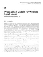
elements may differ from system to system. In this section, we present a generic WLL
architecture (see Figure 1.2).
PSTN
Internet
ISDN
ATM
BTS
BTS
BTS
Air
Interface
FSU
FSU
FSU
Telephone
Telephone
Computer
FAX
PC Telephone
Figure 1.2 Generic WLL architecture
Generic WLL System Architecture 9
The fixed subscriber unit (FSU) is an interface between subscriber's wired devices and
WLL network. The wired devices can be computers or facsimiles as well as telephones.
Several systems use other acronyms for FSU such as the radio subscriber unit (RSU), or
the fixed wireless network interface unit (FWNIU). FSU performs channel coding/decod-
ing, modulation/demodulation, and transmission/reception of signal via radio, according
to the air-interface specification. If necessary, FSU also performs the source coding/
decoding. FSU also supports the computerized devices to be connected to the network
by using voice-band modems or dedicated data channels.
There are a variety of FSU implementations. In some types of commercial products, the
FSU is integrated with the handset. The basic functions of this integrated FSU are very
similar to those of the mobile handset, except that it does not have a rich set of functions
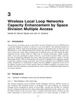
for mobility management. Another example of FSU implementation is a high-capacity,
centralized FSU serving more than one subscriber. Typical application of this type of
FSU can be found in business buildings, apartment blocks, and the service area where
some premises are located near by (see Figure 1.3).
FSU is connected with the base station via radio of which band is several hundreds of
MHz till up to 40 GHz. Since WLL is a fixed service, high-gain directional antennas can
be used between FSU and the base station, being arranged by line-of-sight (at least,
nearly). Thus, WLL signal channel is a Gaussian noise channel or strong Rician channel
(not a Rayleigh fading channel) [6]. This increases drastically the channel efficiency and
the capacity of the system.
The base station is implemented usually by two parts, the base station transceiver system
(BTS) and the base station controller (BSC). In many systems, BTS performs channel
coding/decoding and modulation/demodulation as well as transmission/reception of signal
via radio. BTS is also referred to as the radio port (RP) or the radio transceiver unit
(RTU).
Wireline
Network
PSTN
Switch
O&M S
BTS
BTS
BTS
BTS
BTS− FSU
FSU
FSU
FSU
FSU
FSU
MultiDwelling Units
Figure 1.3 FSUs serving multiple subscribers
10 Introduction to WLL: Digital Service Technologies
A BSC controls one or more BTSs and provides an interface to the local exchange (switch)
in the central office. An important role of BSC is to transcode between the source codes used
in wired network and that at the air-interface. From the above roles, a BSC is often called the
radio port control unit (RPCU) or the transcoding and network interface unit (TNIU).
WLL systems provide fixed wireless access and therefore they do not need to support
any mobility features like handover, even though some of these systems are based on
cellular standards and products. For a complete comparison between fixed wireless and
cellular systems one should refer to Appendix A.
As one can easily understand from Figure 1.2, the WLL services depend not only on the
functionality of FSU, BTS, BSC, and air-interface specification but also on the service
features provided by the switch in the central office. For example, when WLL is used as a
telephony system, there are the basic telephony services (e.g. call origination, call delivery,
call clearing, emergency call, etc.) and the supplementary services (e.g. call waiting, call
forwarding, conference-calling, calling number identification, etc.). In addition, as in the
wired systems, the features such as custom calling features, Centrex features can be
supported by the switch [4,6]. If the air-interface provides a transparent channel to the
switch, these service features depend totally on the switch functions. So, we hereafter
focus on the wireless transceiver functional blocks as well as on the various WLL system
technologies rather than the service features provided for by the switches.
1.4.1 Wireless Transceiver Functional Blocks
Thanks mostly due to cellular systems and their penetration worldwide, the wireless trans-
ceiver has reached progress levels, which otherwise would be considered intangible.
Advances in the areas of antennas, modulations and digital signal processing (DSP) have
accelerated the design of wireless transceivers into higher levels of functionality, efficiency
and signal quality. Below, we distinguish the functional blocks, which a wireless transceiver
consists of. We have the chance to present some issues regarding each such functional block.
Antennas Spatial diversity receive antennas are used to combat the flat fading. Directive
antennas with a few degrees of beamwidth are generally sufficient to drastically reduce the
delay spread, with the drawback of complete outage of transmission if it exists only in a
non-line-of-sight (NLOS) path. The second drawback is that it can be used only with
temporary fixed terminals unless adaptive phase arrays or switchable antennas are used.
Modulators In wireless communications, the decision upon which modulation will be
used is very critical. It is not only the capacity that must be offered within the reserved
frequency spectrum but also the resistance it has to exhibit to the various types of
interference and noise that characterize the wireless channel. The rapid progress in
cellular/mobile and personal communication services (PCS) has boosted research in this
area. First modulations to be adopted in cellular as well as in cordless systems were p=4-
DQPSK (IS-54, Personal Digital Cellular PDC) and Gaussian Minimum Shift Keying
(GMSK) (Global System for Mobile communications GSM). They proved to be the best
candidates for the wireless channel where multipath propagation, cochannel interference,
fading and shadowing apart from additive noise and intersymbol interference mostly in
TDMA dominate. The success of mobile communications has led a whole class of
research teams to work upon the standards of the third-generation systems that among
Generic WLL System Architecture 11
the others they will have to support higher data rates. At the same time, new wireless
communication systems thrive to find a trade-off between the higher baud-rate and the
most efficient data compression keeping the signal quality at acceptable levels. When,
however, the baud-rate increases, the multipath effects are intensified. One solution to
combat these effects is to increase the symbol length so that it becomes only a fractional
time of the mean delay spread. This can be achieved by using either M-ary modulation
types (such as B-O-QAM and Q-O-QAM) or multicarrier modulation (such as offset
frequency-division multiplexing, OFDM), with the drawbacks of increased hardware com-
plexity, increased transmitted power levels, and high-amplitude linear microwave power
amplifiers. Alternatively, direct sequence spread spectrum (DSSS) resolves the different
delays by correlation techniques. However, since digital correlators are generally limited
to a few tens of megahertz, and the sequence length has to be greater than 10 to 100 chips,
this solution is not always feasible for high data rate transmission even for the case of
indoor communications, where the delay spread is on the order of 10±80 ns.
Filters It is one of the operations cited to be ideally suited for DSP applications. FIR
filtering is a repetitive process performed by multiplying the set of input signal samples
with a fixed set of known filter coefficients. In the example of IS-136 (TDMA), pulse
shaping is done at a transmitter with a square-root raised cosine filter, and appropriate
matched filtering has to be done at a receiver. Although straightforward, there are
instances when care needs to be exercised to make sure that filtering is executed within
the minimum possible number of machine cycles.
Receiver Synchronization Circuits There exist several layers of synchronization [10]:
Ð Frequency synchronization
Ð Carrier recovery for coherent demodulation
Ð Symbol timing recovery
Ð Slot and frame synchronization
Most synchronization methods require that they be accomplished through initial
acquisition, tracking, and reacquisition. Synchronization of frequency is typically accom-
plished through the use of automatic frequency control (AFC). In digital receivers, the
received signal constellation rotation is monitored in a DSP and a phase error based
measurement is differentiated and filtered. This error signal is used in a digital VCO to
come up with a number, which will correct the operation of an analogue component
(VCXO). From the DSP this control signal can be sent through the dedicated D/A to a
digitally controlled device or converted to a pulse-width modulation form suitable for
transmission as an analogue signal. Algorithms for frequency synchronization are often
feedback-based and require the operation of the PLL suitable for DSP implementations.
Carrier recovery is associated with coherent receivers, where knowledge of the phase of
the received signal is required. It is simple to implement a fully digital phase correction
algorithm in DSP firmware, again by monitoring the phase error in a signal constellation.
It is the decision of implementers if the phase correction is done in the analogue compo-
nent based on a digital control signal or fully digitally implemented.
In the example of IS-136, frame timing is the first synchronization that can be accom-
plished using training symbols at the beginning of all data frames. Frame synchronization
is accomplished by correlation of the received waveform with the replica of the training
12 Introduction to WLL: Digital Service Technologies
waveform(s) known to the receiver. This is the feed-forward type of operation. The
receiver repetitively correlates the signal until it identifies a peak in the correlation
function, and based on the peak's location in time adjusts its timing. It is important to
note that in cases where a frequency offset exists the correlation will fail when it is done
only against the ideal original training waveforms. For good performance in realistic
environments it is also necessary to correlate the received signal against frequency-shifted
original waveforms. A typical DSP is ideal for correlation operations. Tracking of
the frame timing can be accomplished by the same operation, except that the span of
the received signal, which needs to be correlated, is significantly smaller since we are close
to the actual timing. Here, though, one has the choice of implementing better resolution.
Symbol timing recovery makes sure that a received signal waveform is sampled as close
as possible to the optimal sampling point for detection. Since it is desirable to have A/D
converters operate at the slowest possible rate, it is required to be able to finely change the
sampling position. Indeed, one can choose to adjust the sampling phase of an A/D
explicitly. However, more and more often in digital receivers, the preferred choice is to
let the converter keep sampling at an arbitrary phase and to use digital interpolation to
find the value of the signal at the optimal sampling point from two or more neighbouring
samples of an arbitrary phase.
Equalizers The fact that wireless channels have an associated delay spread which causes
intersymbol interference requires in some instances that this be compensated for. However,
the higher the symbol rate is, the more complex and time- and power-consuming the device
is. For a 24.3 kbps IS-136 system, the delay spread which causes trouble and requires
an equalizer is on the order of 10 ms. Two principal techniques are used for equaliza-
tion: decision-feedback equalizers (DFEs) and maximum-likelihood sequence estimators
(MLSEs). Equalization is one of the most MIPS-intensive functions in cellular phone
receivers. Although equalizers are not always needed, since channels often have smaller
delay spreads as happens in WLL, receivers/DSPs have to be designed to be able to handle
equalization. DFEs consist of two FIR filters and are amenable to DSP implementations.
MLSE equalization requires clever memory addressing approaches, which DSPs support.
Channel Coders/Decoders Channel coding is almost always applied in cellular/WLL
communications systems. FEC ( forward error correction) codes and interleaving tech-
niques (to randomize the errors) are used to correct a certain number of bit errors, thus
giving a coding gain (relative to the received power). However, this has the drawback of
needing an increased transmitted bit rate, leading to higher levels of ISI and creating more
decoding delays and complexity due to the necessary interleaving memories. The oper-
ation of coding is always simpler than decoding. Both block-code and convolutional-code
decoding can be demanding in terms of the number of cycles required. DSP vendors are
paying particular attention to efficient software implementations and/or building special-
ized hardware for trellis search techniques, which are effective for various decoding
schemes. These accelerators are probably the first of a number of accelerators that will
deal with speeding up the operation of DSPs. It is interesting to note that Viterbi MLSE
equalization techniques can sometimes share trellis-searching structures with channel code
decoders. This is most obvious in GSM, where modulation is binary.
Automatic Gain Controllers While propagating through a wireless channel, a signal can
experience dramatic changes in power levels. Standard deviation of a signal due to
Generic WLL System Architecture 13
shadowing is on the order of 8±12 dB, whereas Rayleigh fading can cause as much as
30±40 dB of rapid signal power fluctuations. It is not always desirable to get rid of all
Rayleigh fading fluctuations (especially when they occur rapidly), but shadowing needs to
be compensated for. Automatic gain control schemes in modern receivers collect and
process data in the digital domain, and then send control information to analogue
components, which adjust, signal power levels prior to A/D converters. It is not usual
to have overdesigned A/Ds (in terms of the number of bits), which would let DSPs cover
most of the dynamic range of radio signals.
1.5 WLL System Technologies
Early WLL systems used standard cellular and cordless technologies to gain access to
spectrum. These are at low frequencies, which have become congested and expensive, as
mobile operators are able to pay premium rates. In our days, however, WLL deployments
also utilize other proprietary systems, narrowband or broadband in frequency bands
that have been provided by ITU on a worldwide basis. In general, the frequency bands,
which have been used or standardized for WLL service, are described in Table 1.2.
1.5.1 High-Range Cellular Systems
The high-range cellular systems support high mobility and can be characterized by the
wider coverage with relatively low data rate. These systems include the second-generation
digital cellular systems using 800 MHz band (e.g. IS-95A, and GSM) and their up-banded
variations for the personal communications services (PCS) using 1.8±2.0 GHz band (for
example, W-CDMA and IS-95B as an up-banded version of IS-95A, and DCS-1800 as an
up-banded version of GSM). Since cellular systems are capacity limited due to the limited
spectrum resources, they have turned to efficient multiple access techniques such as
TDMA and CDMA. Although these two techniques are more efficient than FDMA, it
is difficult to say which one is superior. Appendix B touches properly this matter.
Table 1.2 Frequencies used or standardized for WLL
Frequency Use
400±500 MHz Rural applications with mostly analogue cellular systems
800±1000 MHz Digital cellular radio in most countries
1.5 GHz Typically for satellites and fixed links
1.7±2 GHz Cordless and cellular bands in most countries
2.5 GHz Typically for Industrial, Scientific and Medical (ISM) equipment
3.4±3.6 GHz Standardized for WLL around the world
10 GHz Newly standardized for WLL in some countries
28 GHz and 40 GHz For microwave distribution systems around the world
14 Introduction to WLL: Digital Service Technologies
Among the above-mentioned systems, we briefly outline TDMA (IS-136, GSM), and
CDMA (IS-95A, IS-95B, W-CDMA) systems [11].
1.5.1.1 TDMA (IS-136 / GSM)
TDMA is a narrowband system in which communications per frequency channel are
apportioned according to time. For TDMA system, there are two prevalent standards:
North American Telecommunications/Electronics Industry Association (TIA/EIA) IS-136
and European Telecommunications Standards Institute (ETSI) Global System for Mobile
Telecommunications (GSM). The IS-136 and GSM standards use different modulation
schemes (i.e. p=4-QPSK for IS-136 and GMSK for GSM). Also, the channel bandwidth of
the two systems is different (30 kHz for IS-136 and 200 kHz for GSM). GSM has a frame
length of 4.615 ms instead of 40 ms for IS-136. The operational frequencies of these TDMA
schemes differ and only GSM supports frequency hopping. GSM uses Regular Pulse
Excitation Long Term Predictive (RPE-LTP) voice coding algorithm at full rate of 13 kbps
or half-rate 6.5 kbps and Enhanced Full Rate at 12.2 kbps whereas IS-136 uses Vector Sum
Excited Linear Predictor VSELP at 8 kbps, IS-641-A at 7.4 kbps and US1 at 12.2 kbps. The
maximum possible data rate achievable is 115.2±182.4 kbps with General Packet Radio
Service supported from GSM and 43.2 kbps for IS-136. They both use hard handover.
1.5.1.2 CDMA (IS-95A, IS-95B, W-CDMA)
CDMA (IS-95A) is a direct sequence spread spectrum (DSSS) system where the entire
bandwidth of the system 1.25 MHz is made available to each user. The bandwidth is many
times larger than the bandwidth required transmitting information. In CDMA systems
pseudonoise (PN) sequences are used for the different user signals with the same transmis-
sion bandwidth. For IS-95, a frame length of 20 ms has been adopted. Regarding voco-
ders, it uses Qualcomm Code Excited Linear Prediction QCELP at 8 kbps, CELP at
8 kbps and 13 Kbps. Compared to the TDMA counterparts, it uses soft handover and
either QPSK or O-QPSK as the modulation format.
IS-95-A [12] standard has been developed for a digital cellular system, operating at
800 MHz band. ANSI J-STD-008 [13] being an up-banded variation of IS-95 is a standard
for PCS systems, operating at 1.8 $ 2.0 GHz band. Recently, IS-95-B [14] merges IS-95-A
and ANSI J-STD-008.
IS-95 based CDMA WLL can support two rate sets. A code channel (that is, a traffic
channel) operates at maximum of 9.6 kbps with the rate set 1 or 14.4 kbps with rate set 2.
Using rate set 1 (rate set 2), the system supports 8 kbps (13 kbps) Qualcomm's codebook
excited linear predictive (QCELP) vocoder.
IS-95B offers high-rate data services through code aggregation. In IS-95B systems,
multiple codes (up to eight codes) may be assigned to a connection. Thus, the maximum
data rate is 76.8 Kbps using rate set 1 or 115.2 Kbps, using rate set 2. Since IS-95B can be
implemented without changing the physical layer of IS-95A [15], it is relatively easy for
the vendor of IS-95 WLL system to develop the IS-95B WLL system.
In mobile IS-95 systems, a sectored cell is designed with three sectors in usual. As
mentioned above, in WLL systems, the antennas for BTS and FSU can be arranged by
line-of-sight and this reduces interference from the other user. So, the CDMA WLL cell
can be designed with six or more sectors [6]. This increases the frequency efficiency and
the system capacity.
WLL System Technologies 15
Both IS-95A and IS-95B have some limitations in supporting high-rate data or multi-
media services because of the insufficient maximum data rate per channel. An alternative
technology to cope with this problem is the wideband CDMA (W-CDMA) [16]. In
comparison with the existing narrowband CDMA systems, W-CDMA systems use higher
chip rate for direct sequence spread spectrum and, thus, spread its information into wider
spectrum bandwidth (typically, equal to or over 5 MHz). Thus, data rate per code channel
in W-CDMA can be higher than that in IS-95 systems. Note that all of the major
candidates for radio transmission technology (RTT) of the international mobile telecommu-
nications-2000 (IMT-2000) systems have proposed W-CDMA for next-generation mobile
communication systems (e.g. [17±19]).
Below, the technical characteristics and the services of a current WLL deployment
based on W-CDMA are described. The downlink (from BTS to FSU) uses the band
from 2.30 to 2.33 GHz and the uplink (from FSU to BTS) uses the band 2.37 $ 2.40 GHz.
Thus, the bandwidth of each link is 30 MHz. The spreading bandwidth can be either
5 MHz or 10 MHz. For both spreading bandwidths, the information bit rates are 8, 16, 32,
64, and 80 kbps. For the case of 10 MHz spreading bandwidth, 144 kbps of information
bit rate is also available.
The WLL standard defines several options for voice codec: 64 kbps PCM (ITU-T
G.711), 32 kbps ADPCM (ITU-T G.726), 16 kbps LD-CELP (ITU-T G.728), and
8 kbps conjugate structure algebraic-code-excited linear prediction (CS-ACELP, ITU-T
G.729). However, the service provider seems to offer voice services using 16 kbps
LD-CELP and 32 kbps ADPCM since those give toll quality of voice with adequate
system capacity. As the voice-band data services, G3 facsimile and 56 kbps modem is
planned.
For packet mode data transmission, some dedicated channels, which are separated
from voice channels, are provided. They are the packet access channels in uplink and
the packet traffic channels in downlink. Using these channels, packet data services up to
128 kbps are offered. In addition, ISDN BRI is also provided.
1.5.2 Low-range Cordless Systems
The advantage of the high-range radio system is the large coverage area of the base
stations and the degree of mobility at which access can be supported. The trade-off,
however, is low quality voice and limited data service capabilities with high delays. The
low-range systems are disadvantaged in coverage area size and user speeds, which is not
so important. The advantages include high-quality, low-delay voice and high-rate data
capabilities. In comparison with high-range systems, low-range systems provide more
wireline-like services. The range of a WLL, however, can be extended via point-to-point
microwave hop using a translator which can up-convert signal frequencies in a spectral
band to microwave or optical frequencies, and then down-convert to the signal at the
remote cell sites before connecting to WLL terminals or buildings. There are several
standards for low-range systems. The representative examples are the digital enhanced
cordless telecommunications (DECT) [11] and its North American variation Personal
Wireless Telecommunication (PWT), the Personal Access Communications System
(PACS), and the Personal Handy-phone Services (PHS). All these standards adopt the
TDMA technology.
16 Introduction to WLL: Digital Service Technologies
1.5.2.1 Digital Enhanced Cordless Telecommunication (DECT/PWT)
DECT is a radio interface standard developed in Europe mainly for indoor wireless
applications and being deployed for WLL applications as well during the last years.
Personal Wireless Telecommunications (PWT) is a DECT-based standard developed by
the Telecommunications Industry Association (TIA) in the United States for unlicensed
personal communications services (PCS) applications. PWT-Enhanced is the version, that
is suitable for licensed PCS applications [20].
DECT originally supports small cells (radius of 100 $ 150 m) with pedestrian-speed
mobility [21]. To use DECT in WLL applications, one of the most important problems
to be solved is to extend the maximum coverage of a fixed part (i.e. BTS). A solution is to
use directional antennas, by which the maximum diameter of a cell can be extended up to
several kilometers. For rural applications, using repeaters at the expense of capacity can
extend the coverage [8].
The basic unit of channel in DECT is a time slot per TDMA frame, operating at
32 kbps. If data rates higher than 32 kbps are required, multiple time slots per frame are
used. Otherwise, if the requested data rate is lower than 32 kbps, several FSUs can share a
32 kbps channel by skipping time slots. DECT offers toll quality digital speech and voice-
band modem transparency either via a 32 kbps ADPCM codec (ITU-T G.726) or as a
64 kbps PCM (ITU-T G.711) bearer service [22]. DECT provides up to 504 Kbps full
duplex data transfer and of course BRA ISDN [23]. Since all user information is
encrypted, there is confidentiality between the different users belonging to a same cell.
DECT has signalling compatibility with basic ISDN and GSM. For more detailed aspects
of DECT WLL, one can refer to ANSI J-STD-014 [24].
For Europe, DECT uses Gaussian minimum shift keying (GMSK) with a bandwidth of
1.728 MHz and 12 time slots per carrier. DECT does not efficiently utilize the unlicensed and
10 MHz licensed bands in the United States. Therefore, the protocol was modified to use p/4
quadrature phase shift keying (p/4-QPSK) which allows more efficient use of the spectrum.
While other PCS technologies separate the band into a handset transmit band and a
base station transmit band (FDD), PWT uses time-division duplex (TDD) with both the
handset and base station transmitting on the same frequency (at different times). PWT has
24 time slots in 10 ms. Twelve slots are defined for base-to-handset transmission, and 12
are defined for handset-to-base transmission. The overall data rate for voice for handset/
base is 32 kbps using adaptive differential pulse code modulation (ADPCM), which pro-
vides toll-quality voice. The transmission path between handset and base station uses a
pair of time slots on the single RF channel.
PWT uses dynamic channel allocation (DCA) to assign frequencies to the channels; as
the name implies, the frequencies are allocated right before their use. The DCA mechan-
ism provides efficient use of the valuable radio spectrum. The size of the cell covered by
an RFP is rather small, less than 150 m for urban applications and 1±2 km for rural
applications. For rural applications the coverage can be extended by using repeaters at the
expense of capacity. DECT is primarily designed to support pedestrian-speed mobility.
This speed is typically less than 10 km/hr.
1.5.2.2 Personal Access Communication System (PACS)
PACS employs TDMA/TDM on the radio interface using p/4-QPSK modulation at
a symbol rate of 192 Kbaud [7±8,25±26]. The radio frame is 2.5 ms in duration with
WLL System Technologies 17
8 bursts/frame. PACS uses International Telecommunications Union-Telecommunications
Standardization Sector (ITU-T) standard 32 kbps ADPCM speech coder and can maintain
very good voice quality with two or three speech coders in tandem. Optionally, 16 Kbps
low-delay code-excited linear prediction (LD-CELP) being defined as ITU-T G.728 can be
used.
For voice-band data, PACS provides 64 Kbps pulse code modulation (PCM) connection
(ITU-T G.711) by aggregating two time slots. This service is used to support all voice
band modems including 56 Kbps modems. PACS supports circuit mode and packet mode
data services. In addition, individual message service and interleaved speech/data service
are also provided.
. Circuit-mode data service: PACS offers reliable real-time data transport service using
link access procedure for radio (LAPR). LAPR operating in a 32 Kbps channel provides
a data throughput of more than 28 Kbps at wireline error rate (10
À6
).
. Messaging services: This is two-way point-to-point message service for large file trans-
fer up to 16 Mbytes. The messages can contain text, image, audio, and video files.
. Packet-mode data service: This is a shared, contention-based, RF packet protocol using
a data sense multiple access contention mechanism. It supports FSU by using single
time slot (32 Kbps) or multiple time slots (up to 256 Kbps) per TDMA frame. The
applications being suitable over the PACS packet channel are wireless Internet access
and mobile computing, etc.
. Interleaved Speech/Data: It provides the ability to transmit both speech information
and data information by using a single 32 Kbps time slot. Data is transmitted during
the silent period of voice.
Low-power PCS systems, such as PACS, require radio port (RP) operating frequencies
to be assigned automatically and autonomously, eliminating the need for manual fre-
quency planning. The automatic frequency assignment in PACS is called quasi-static
autonomous frequency assignment (QSAFA). QSAFA is a self-regulating means of select-
ing individual RP frequency channel pairs that function without a centralized frequency
coordination between different RPs.
PACS uses frequency-division duplex (FDD) for the licensed version and TDD for the
unlicensed version. The specification of PACS allows for low-complexity implementations
of both subscriber units (SU)s and radio ports (RP)s in order to reduce wireless access
system costs and network costs. SU peak transmit power is 200 mW, and the average
power is 25 mW. The RPs function largely as RF modems, depending on the centrally
located RPCUs for most of the functionality traditionally associated with port electronics.
In PACS, the SU determines when and to which RP to perform automatic link transfer
(ALT) or handoff. The ALT decisions are made by the SU in order to offload this task
from the network and to ensure robustness of the radio link by allowing reconnection of
calls even when radio channels suddenly become poor. The SU first measures the radio
signals. If certain criteria are reached based on the measurements, ALT is performed. The
SU determines the new RP for ALT and executes the transfer with the network. FDD
provides an advantage over TDD in handling port-to-port synchronization. In TDD
operations, both the uplink and downlink of a channel use the same frequency. This
requires that RPs be synchronized in order to minimize the interference from each other.
In FDD operations, uplink and downlink are on different frequencies. This results in
better interference management and does not require adjacent port synchronization,
18 Introduction to WLL: Digital Service Technologies
which helps reduce the RF cost of the equipment. The frame delay in PACS is about 5 ms.
Such a very low delay negates the need for an echo canceller circuit in the radio
equipment. In PWT and other radio technologies, an echo canceller is typically required
[8±9].
There are two types of user terminals in PACS/WLL: portable handset (subscriber
unit) and fixed access unit. The fixed access units convert the radio signal to a RJ-11
interface signal to the customer premises equipment. The user terminal communicates
with the radio port following the JTC/PACS air interface (TDM/TDMA at the 1850±
1910 MHz and 1930±1990 MHz frequency bands). The coverage area of a radio port
(RP) is 0.5±2 km for the portable handsets and more than 2 km for the fixed access
units. The RP connects to the radio port control unit (RPCU) by E1, T1, HDSL, or
DSL technologies.
1.5.2.3 Personal Handyphone System (PHS)
PHS is a low-range personal communications services (PCS) technology that was de-
veloped in Japan by a consortium of companies to support very-high-density pedestrian
traffic and WLL. It is built on a foundation of digital cordless technology and microcell
architecture.
PHS uses p=4-DQPSK in the RF band of 1900 MHz as DECT with a bandwidth of
300 KHz per channel. Each channel consists of either 3 or 4 time-slots. However, it has a
better spectrum efficiency than DECT since it has 4 time slots per 300 KHz carrier instead
of 12 slots per 1.728 MHz carrier. The multiple access scheme used is TDMA/TDD and
the voice coding is 32 kbps ADPCM. PHS makes use of Dynamic Channel Assignment
and is more flexible in network planning and more cost-effective and suitable for WLL.
Due to its architecture, it is less sensitive to multipath and delay and has bigger cell
coverage. In urban areas, it uses 5 times fewer base transmission stations than DECT
when covering the same area, whereas in rural areas PHS has a wider service coverage
than DECT since it is more tolerant of delay spread.
PHS personal stations (PSs) consist of handheld units that can operate as simple
cordless phones, as transceivers for communications with other personal stations, or as
mobile terminals to access the public switched telephone network (PSTN). The mode of
operation must be selected by the user. The cell stations (CSs) handle the control and
transmitter functions. The CS consists of the antenna and the base station unit. Its output
power ranges from 100 mW to 500 mW according to the number of users in the area to be
served. CSs are usually mounted on utility poles, payphone boxes, and roofs. The CS is
connected to the fixed network with integrated services digital network (ISDN). The
control station is essentially a database unit for storing subscriber data.
1.5.3 Proprietary Narrowband WLL
The number of competitors in the local loop and service capability, influences likely
penetration, and hence capacity and range requirements of the technology solution.
Among the several WLL systems already in use in various markets, we outline the
TDMA proprietary systems E-TDMA of HNS and Proximity I/II of Nortel, the
CDMA proprietary systems QCTel of Qualcomm, Airloop of Lucent and Airspan of
DSC, and finally the FH-CDMA/TDMA system Multigain of Tadiran.
WLL System Technologies 19
1.5.3.1 HNS E-TDMA
E-TDMA [27] is an extension to the IS-136 cellular TDMA standard that provides support
for WLL with increased capacity and improved network performance while maintaining the
large coverage area feature of other cellular standards. E-TDMA offers a choice of sub-
scriber unit platforms including single subscriber units (SSU) and multiple subscriber units
(MSU) capable of supporting up to 96 lines, depending on the subscriber traffic load and
MSU provisioning. The single subscriber units support high-capacity digital voice, fax, and
data transparently using a standard RJ-11 interface, and enable multiple terminal connec-
tions as simple extensions on a single access unit or per directory number. Such units are
appropriate for locations with low population densities such as residences and small
businesses. Multiple subscriber units provide access to the WLL system in areas of high
population densities such as hotels and apartment buildings. MSU and radio resources are
allocated on a call-by-call basis, thereby reducing the required hardware.
The E-TDMA base station provides an improved control channel to dynamically assign
channels and time-slots to active speakers. A 5 kbps rate voice coder is also used which
more than doubles the capacity over IS-136. Finally, the implementation of discontinuous
transmission (DTX) along with digital speech interpolation (DSI) means that both the base
station and the subscriber station transmit only when speech is present (about 40 percent
of the time), thus sharing the radio resource effectively with other users. E-TDMA
supports a wide variety of country variant signalling. Tones and line signalling variations
are software programmable, and in a number of cases can be set via system parameters.
Both 16 kHz metering and Polarity reversal signalling mechanisms for pulse signalling can
be supported, if they are generated and supported by the switching system. Thus, E-
TDMA can interface with a wide variety of metering and public pay phone equipment.
Depending on the subtending switching equipment, E-TDMA is capable of supporting
virtually all of the vertical features and CLASS features recommended by TR-45, as listed
above, including call waiting, call forwarding, conference calling, and so on. The main
strengths of cellular-based WLL systems over low-range PCS based WLL systems include
coverage, speed of deployment, and spectrum efficiency. The fundamental disadvantage is
the limited range of available user bandwidth. This trade-off implies a market for both
system types.
1.5.3.2 Nortel Proximity I/Proximity II
Nortel makes a class of narrowband WLL systems under the banner Proximity which are
not based on cordless or cellular technologies. Proximity I is a proprietary TDMA system
developed in conjunction with the United Kingdom WLL operator Ionica, one of the first
operators in the world to deploy a proprietary WLL system. Proximity I offers a wide
range of services, including 64-kbps voice and data links and a second-line capability.
Subscriber units link to base stations over the air-interface, and base stations then are
connected directly back to a PSTN switch.
Proximity II is an upgraded version, that is more flexibly tailored to suit each individual
operators' requirementsÐfrom small city based systems supporting a few thousand
customers up to large nationwide systems with capacities in excess of one million.
Proximity II provides also BRA ISDN service and enables high-rate Internet access at
128 Kbps. Its compact base station has a capacity of 2000 lines and it may be located up
to 40 km from the users. The user premises equipment supports one or two lines for PSTN
20 Introduction to WLL: Digital Service Technologies
or ISDN terminals. Its System Management is compatible with public network switches
through V5.2 signalling.
Both system versions use TDMA channels of bandwidth 3072 kHz in a cluster size of 3,
and quadrature phase shift keying (QPSK) modulation format. Up to 54 TDMA bearers
can be accommodated in the 3.4 ±3.6 GHz assignment using frequency division duplex
(FDD) either 50 or 100 MHz with a maximum of 18 channels on any given base station.
DCA is not provided, but it is relatively easy to reconfigure the frequency assignment
from the operations and maintenance centre.
1.5.3.3 Qualcomm QCTel
Qualcomm's QCTel CDMA WLL System is a Fixed Wireless Access WLL [28]. A basic
six-sector QCTel system may support 24 000 subscribers. The QCTel technology supports
8 kbps voice and up to 7.2 kbps data rate. QCTel supports limited mobility, and the
subscriber unit can be a portable handset. The handset communicates with the base
station transceiver using the IS-95 air-interface (CDMA/FDD at the 800 MHz,
900 MHz, and 1.8±2.2 GHz frequency bands). The handset can support multiple lines.
The transmit power is 2 W (with power control).
The base transceiver station (BTS) communicates with the handset using the IS-95 air-
interface. The maximum transmit power is 50 W. The cell range is 25 km. The capacity is up
to 45 voice channels. Up to 20 BTSs may be collocated with the base station controller (BSC)
at the central office. Or 30 BTSs per area may be connected to a BSC using the T1/E1
technology (up to three areas). The BSC is collocated with a central office, which connects to
a switch of the PSTN using T1, E1, T3, or E3 digital multiplexed trunks. The call control is
done by R2 inband signalling, and the OMC signalling is done by SS7 or X.25.
1.5.3.4 Lucent Airloop
The Lucent Airloop technology is another proprietary CDMA-based system developed
for a wide rank of customers. It operates mainly in the 3.4-GHz band using 5-MHz wide
channels, each supporting 115 16-kbps channels. To support 32-kbps ADPCM, two
channels are used simultaneously. The spreading code is 4096 kbps; thus, for a 16-kbps
data rate, a spreading factor of 256 is used. The system employs a network of radio base
stations (RBSs) to provide coverage of the intended service area. The main functional
blocks of the network are the following:
. Central Office (CO): It contains digital switching and network routing facilities
required connecting the radio network to ISDN and the Internet.
. Central Access and Transcoding Unit (CATU): It controls the allocation of radio
resources and ensures that the allocation is appropriate to the service being provided,
for example, 64-kbps digital, 32-kbps speech, ISDN. It also provides transcoding
between various speech-coding rates and the switched 64-kbps PCM.
. Central Transceiver Unit (CTU): It provides the CDMA air-interface. It transfers
ISDN and plain old telephony (POTS) signalling information transparently between
the air-interface and the CATU.
. Network Interface Unit (NIU): It connects the subscribers to the radio network through
two functional blocks, the intelligent telephone socket (ITS) and the subscriber trans-
ceiver unit (STRU).
WLL System Technologies 21
. The ITS provides the point of connection to the subscriber's terminal equipment, for
example, PABX, telephone, or LAN.
. The STRU is located on the outside of the subscriber's building and consists of an
integrated antenna and radio transceiver. The STRU provides the interface between
the ITS and the CDMA air-interface. The STRU is connected to the ITS by a standard
four-wire telephone or data networking cable.
The type of service being provided by the connection determines the number of
subscriber connections supported by each NIU. The basic NIU connection provides a
single ISDN (2B D) connection, effectively giving two unrestricted 64-kbps
channels. The same unit also can he configured as either two or eight individual POTS
lines using ADPCM and Code excited linear predictive (CELP) speech coding, respec-
tively.
The modulation technique employed first takes each 16-kbps channel and adds error-
correction coding to reach 32 kbps. It then uses Walsh spreading with a spreading factor
of 128 to reach the transmitted data rate of 4 Mbps. Finally, it multiplies that by one of a
set of 16 PN code sequences also at 4 Mbps, which does not change the output data rate
but provides for interference reduction from adjacent cells. During design of the network,
each cell must have a PN code sequence number assigned to it such that neighbouring
cells do not have the same number.
1.5.3.5 DSC Airspan
The DSC Airspan system was developed in conjunction with BT, which is using the
system for rural access at 2 GHz. The system provides 64-kbps voice channels and support
for up to 144 kbps ISDN services. DSC claims a cluster size of between 1 and 3, depending
on the environment. Voice currently is provided using 64-kbps PCM and ADPCM at
32 kbps. The system currently provides 2B D ISDN per subscriber or, alternatively,
2 Â 64 kbps data channels. Up to 6 Â 64 kbps data channels can be achieved by combining
three subscriber units.
Radio channels are 3.5 MHz wide. Each 3.5-MHz channel provides up to fifteen
l60-kbps radio bearers. With the current deployment, each 160-kbps bearer can provide
two 64-kbps voice-channels or four 32-kbps voice channels, each to a different house.
1.5.3.6 Tadiran Multigain
Tadiran markets its proprietary system as FH-CDMA/TDMA. In the Tadiran system,
users transmit in a given TDMA slot. However, the actual frequency in which they
transmit changes from burst to burst, where a burst lasts 2 ms (hence, there are
500 hops/s). In a given cell, no two users transmit on the same frequency at the same
time. However, users may transmit on the same frequency in adjacent cells. By employing
different hopping sequences in adjacent cells, if a collision does occur it will be only for a
single burst. Error correction and interleaving largely can overcome the effect of such a
collision. The system has the advantages of the simplicity of a TDMA system coupled
with some of the `interference-sharing' properties that make CDMA spectrally efficient.
Tadiran claims that a cluster size of 1.25 can be achieved by that approach when
directional antennas are deployed. In practice that seems somewhat optimistic, and it
might be expected that a cluster size of 2 would be more realistic.
22 Introduction to WLL: Digital Service Technologies
The system uses a voice coder of 32 kbps. It employs TDD, in which both the uplink
and the downlink are transmitted on the same frequency but at different times. Each
1 Â 1 MHz channel supports eight voice channels. Hence, 16 voice channels per
2 Â 1 MHz can be supported before the cluster effect is taken into account, and assuming
a cluster size of 2, around 8 voice channels/cell/2 Â 1 MHz.
1.5.4 Proprietary Broadband WLL
A number of systems have been proposed and implemented that use WLL techniques to
deliver broadcast TV [29]. Such systems fall into a niche somewhere between terrestrial
TV broadcasting and WLL telephony delivery. They offer advantages over terrestrial TV
broadcasting in that they can provide many more channels and may offer advantages over
the other WLL systems discussed here in their ability to deliver high-bandwidth services.
Broadly speaking, the only difference between WLL and microwave distribution is that
the latter tends to be transmitted at much higher frequencies, such as 40 GHz, where
significantly more bandwidth is available and hence wider bandwidth services can be
offered. However, such higher frequencies result in lower propagation distances and more
costly equipment. Further, rain fading can be a significant problem in some regions at
such frequencies, making reception unreliable.
The first microwave distribution systems were implemented in the United States, where
they were called microwave multipoint distribution systems (MMDS). The systems tended
to operate between 2.15 GHz and 2.682 GHz and provided a maximum of 33 analogue TV
channels to communities at a bandwidth of 500 MHz. They were entirely broadcast
systems, and no return path capability was provided. However, compared to cable TV
and satellite systems that support 30±60 and 150±200 video channels respectively, MMDS
operators had to resort to digital compression techniques to become competitive. Many
such systems are still in existence between 2.5 and 3 GHz, but with the introduction of
digital broadcasting they will become increasingly outdated.
After MMDS, digital distribution systems operating at around 29 GHz were introduced
in the United States and the Asia±Pacific countries. The systems, known as Local multi-
point distribution systems (LMDS) [30], can provide many more channels with a higher
quality but lower range. It is considered as a strong candidate for next-generation broad-
band WLL (B-WLL) services. The spectrum for LMDS differs from country to country
but it is usually in the 20 $ 30 GHz band. The LMDS applications include a variety of
multimedia services such as POTS, ISDN, broadband ISDN (B-ISDN), television program
distribution, videoconference, VOD, teleshopping, and Internet access. LMDS can offer
two-way wireless services, whereas MMDS and satellite systems require terrestrial wired
networks to communicate back to the headend, for example, to select programming or use
VCR-type controls on video-on-demand (VOD) programming.
The primary disadvantages of both the MMDS and LMDS are cochannel interference
from other cells and limitations on coverage (up to 25 miles for MMDS and up to 5 miles
for LMDS) [31]. Millimetre-wave radio signals do not penetrate trees. Thus, line-of-sight
propagation paths are required. This requirement can make antenna placement on sub-
scriber homes challenging. Despite, however, the fixed locations of both transmitter and
receiver, the influence of motion of traffic and foliage, even in a line-of-sight location,
creates a fading environment, which is much more hostile than measured for conventional
cellular mobile systems, at say, 2 GHz. Temporal fades of over 40 dB at the rate of at most
WLL System Technologies 23
a few (< 2) hertz are frequently seen in these environments, imposing very stringent
requirements on the error correction coding of the transmitted bitstream.
Another serious problem in wireless multimedia services is traffic asymmetry between
uplink and downlink [16±18,32]. For example, let us consider Internet access or remote
computing. In these applications, short commands are transmitted via uplink, whereas
relatively large files are transmitted via downlink. In these cases, if both links have the
same bandwidth, the system capacity can be limited by the downlink. This, in turn, results
in bandwidth waste of uplink and, eventually, spectrum inefficiency. To cope with traffic
unbalance, the spectrum allocation for LMDS is given to be asymmetric between uplink
and downlink. Since LMDS is a FDD system, the downlink bandwidth should be
appropriately wider than the uplink. Another solution for this is to use time division
duplex (TDD) between two links. Thus, CDMA/TDD systems, having both the merits of
CDMA (e.g. in capacity) and the advantages of TDD (e.g. flexibility in resource alloca-
tion), have been attracting many researchers' attention recently [16±18].
Similar initiatives in the United States and Europe have lead to the system operating at
40 GHz, Microwave Video Distribution System (MVDS). Early in the development process
of MVDS, it became apparent that to provide competition to cable and to maximize the
revenues that could be achieved, a return path from the home to the network would be
required. That allows voice and limited data enabling, for example, selection of video
films. Systems capable of providing such a return path are now in a trial stage. The return
path can provide around 20 kbps of data.
MVDS systems still are relatively immature, so it is difficult to provide significant
amounts of information on particular products. It can be seen that in terms of telephony
provision, MVDS is inferior to other WLL systems. However, when telephony is viewed as a
service offered on the back of video distribution, it looks more attractive. It is too early to say
whether the economics of MVDS will allow the telephony component to be sufficiently
cheap so that users will accept its relative shortcomings. However, for many users, telephony
is a critical service that they will not compromise to realize some savings. Hence, at least for
the next few years, it is unlikely that microwave distribution systems will provide an
acceptable WLL service. Instead, they provide a wireless alternative for the cable operator.
1.5.4.1 HNS AIReach Broadband
AIReach Broadband constitutes a powerful platform for offering fibre-quality `last-mile'
wireless solutions that encompass voice, video, data, multimedia, and Internet services. It
aims at serving either individual business customers or multitenant offices/residential com-
plexes. The AIReach Broadband product family consists of two product series. One is ideally
suited for semi-urban or light to medium urban areas whereas the other is suited for medium
to high-density urban areas. They both address the small to medium size business customers
and multidwelling units (MDUs) and they operate either in the ITU/ETSI frequency bands:
3.5 GHz, 10.5 GHz, and 24±26 GHz or in the frequency bands between 24 ±42 GHz. The
maximum data rate achieved per carrier is 4 Mbps and 45 Mbps respectively.
AIReach Broadband system can start with a single radio at the hub and as few as two
subscriber terminals though a completely scaleable hub. It uses 64-QAM as modulation
format achieving one of the highest spectral efficiencies available. Moreover, the high-
capacity product series deploys Tri-Mode Modulation (TMM), which enables balance
between coverage and capacity, since with TMM, a single hub radio can switch modula-
tion modes on a burst-to-burst basis.
24 Introduction to WLL: Digital Service Technologies
AIReach Broadband assigns bandwidth on demand as well as voice and data concen-
tration via dynamic bandwidth management making the economics very competitive to
wireline solutions. Outdoor terminals take up less rooftop space and provide better
installation options. Small indoor terminals with easy front access for all of the cabling
are designed for tight spaces and cluttered environments in telecom closets. The low-
capacity product series offers the following services and interfaces: E1; N Â DS0; Ethernet
and Frame Relay; services with BoD; V5.2; Internet Services; BRA ISDN; ATM; 10
BaseT; V35/X.21. Additionally, the high-capacity product series offers: N Â T1/E1; LAN;
ATM; 10/100 BaseT; PRA ISDN; MPEG2.
1.5.4.2 Motorola SpectraPoint
SpectraPoint has a strong headstart in the direction of facilitating multiplatform integra-
tion via IP and ATM, having been working with Cisco Inc. for most of the last few years
to integrate router switches and other IP components into the LMDS access system.
SpectraPoint already integrates its product series with software, which supports dynamic
changes in modulation from the more robust, low bits-per-Hertz levels to the noise-
sensitive, high-capacity levels as weather conditions change or customers shift the trade-
offs they want to make between bandwidth efficiency and quality of service.
The air-interface of the SpectraPoint platforms already supports QPSK (quadrature
phase shift key) and 8, 16 and 32 QAM (quadrature amplitude modulation) modulation
formats as well as Viterbi and Reed Solomon as Forward Error Correction methods.
Frequency re-use is enhanced via polarization diversity (factory-selectable horizontal or
vertical). The channel spacing is 40 MHz allowing for a 45 Mbps downstream speed and a
2 up to 10 Mbps upstream speed. The average transmitted power is 1 W for the base
station and 100 mW for the subscriber unit.
One of the innovations Spectrapoint brings to LMDS fixed wireless products is the ability
to transport everything in ATM while using time division multiple access to dynamically
alter the amount of bandwidth devoted to any one user's needs. This way, all the users on a
single RF LMDS channel, which now supports up to 45 Mbps and in due course 155 Mbps,
can pay for services on an as-needed basis, allowing service providers to more efficiently
allocate bandwidth, that is not in use from one moment to the next.
1.5.4.3 Nortel Reunion
Reunion is another point-to-multipoint (PMP) systemÐalso referred to as broadband
wireless access (BWA). It is similar in design to cellular or narrowband wireless local
loop systems, but offers bandwidth connection ranges from 64 Kbps up to 155 MbpsÐ
offering great flexibility in serving local access markets. Reunion's unique Quad-4 archi-
tecture exploits the potential of four access technologies to produce exceptional network
flexibility and efficiency as well as to provide consistency and congruence with wired
networks. The advantage of Quad-4 is that it is able to tailor and optimize the network
deployment. Quad-4 makes FDMA, TDMA, ATM, and IP connections possibleÐall
from a single platform.
. FDMA provides efficiency in delivering high volumes of data.
. TDMA's greater spectrum and cost efficiency is suited for low bandwidth and sporadic
voice and data needs.
WLL System Technologies 25
. ATM is an excellent solution for multimedia applications and high Quality of Service
requirements.
. IP is the technology of choice for low-cost customer premise equipment and end-user
applications to help penetrate the SOHO market.
Reunion portfolio offers High-Rate Data Transfer, LAN/WAN Interconnection, Inter-
net/Intranet Access, Telephony, Voice over IP, Corporate Video Services, Home Banking,
Distance Learning, Tele-Medicine, Video Conferencing, VPN, E-Commerce, Web TV,
Interactive Gaming, Video Streaming. Reunion can be deployed to handle bundled multi-
media services or single service solutions.
The Reunion network architecture consists of the following three major elements:
. The Reunion Base Station, consisting of the Network Node Equipment (NNE) and the
Base Station Transceiver (BTR), facilitates the multiplexing, mapping, modulation, and
transmission of multimedia content to and from the access market. This equipment,
which operates in a variety of downstream and upstream frequencies between 2 GHz
and 42 GHz, offers high-capacity. All of this capacity and performance is packed into a
small footprint.
. The Reunion element management system facilitates the operations, administration,
maintenance, and provisioning of the network.
. A cost-effective integrated CPE meets the needs of the small- to medium-sized cus-
tomer, providing up to four E1/T1 and 10 Base-T circuits, which utilize either TDMA
or FDMA access technologies. A modular CPE, expandable to accommodate future
needs, is used to serve building sites with multiple small to medium tenants as well as
larger, more bandwidth-intensive customers.
1.5.4.4 Alcatel Evolium
The Alcatel LMDS Solutions provides broadband last mile connections to thousands of
subscribers from a single hub. It provides a wireless local infrastructure, using line-of-
sight radio links over distances of up to 5 km, handling full two-way communications for
more than 4000 end users, delivering true broadband capacity, at a bit rate of up to
8 Mbps through a wide variety of narrow- and broad-band communications services.
Alcatel LMDS utilizes co-polarized or cross-polarized, single carrier or multicarrier
radio solutions to get the most out of the allocated spectrum. It supports a Guaranteed
Cell Rate (capacity available at all times) and a Peak Cell Rate (maximum capacity
available whenever there is spare capacity) on a per customer basis.
The air-interface makes use of a patented TDMA frame, which is optimized for any mix of
circuit and packet data applications, with real time Dynamic Bandwidth Allocation. Among
its advantages, there exist fibre-like reliability, 99.995 % availability, 10
À14
BER, encryption
over the air and on-line system upgrades with new features by in-band software download.
Alcatel LMDS operates in frequency bands between 10 and 43 GHz. Services include:
. circuit-switched voice, data or mixed voice/data;
. distributed or centralized architecture;
. multiservice cross-pole or mono carrier pole;
. virtual leased line (T1/E1 or N Â 64 Kbps);
. IP/Ethernet/ATM/Frame relay;
. bandwidth on demand.
26 Introduction to WLL: Digital Service Technologies