SAP 2000 Tutorial Session Notes
Bạn đang xem bản rút gọn của tài liệu. Xem và tải ngay bản đầy đủ của tài liệu tại đây (483.8 KB, 9 trang )
1.051 Structural Engineering Design
Prof. Oral Buyukozturk Fall 2003
SAP 2000 Tutorial Session Notes
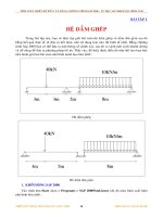
This tutorial provides the basic steps of performing a frame analysis using SAP
2000. It is based on the design project example shown below, the complete
solution of which is provided as a handout.
16@21'
26'
34'
26'
20'
5@13'
15'
Results of Preliminary Analysis:
Slab thickness: 9 in
Beam dimensions: 14”x31”
Exterior columns: 14”x18”
Interior columns: 16”x22”
Loads:
Exterior beams: LL=0.72 kips/ft
DL=1.85 kips/ft
Interior beams: LL=0.83 kips/ft
DL=2.10 kips/ft
Wind and Earthquake loads are specified in the appendix. Only earthquake
loads are considered.
The frame is solved in the short direction only since this direction is more critical.
1.051 Structural Engineering Design
Prof. Oral Buyukozturk Fall 2003
Analysis Steps
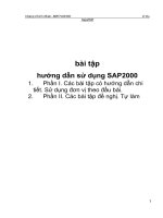
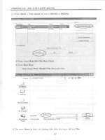
1. Generate the frame geometry from analysis templates.
Menu: File > New model from template
Result
Note: make sure that proper units are selected (shown in the lower right corner)
1.051 Structural Engineering Design
Prof. Oral Buyukozturk Fall 2003
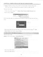
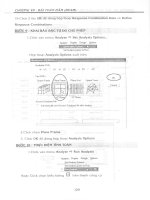
Since we chose the common floor heights and bay spans, we need to move the grids
Menu: Draw > Edit Grids
X-grids before and after
Before After
Z-grids before and after
Before After
Result:
1.051 Structural Engineering Design
Prof. Oral Buyukozturk Fall 2003
2. Set Boundary Conditions
The default boundary condition in the template is simple supports at the bottom. We need
to change those to fixed supports. After selecting these joints, one can either use the menu:
Assign > Joint > Restraints, or the quick menu button at the top
(Restraints is
the first one).
3. Define Material Properties
'
4 ksi 576 ksf
57000 4000 3605 ksi 519120 ksf
60 ksi 8640 ksf
29000 ksi 4176000 ksf
c
c
y
y
f
E
f
E
==
===
==
==
Menu: Define > Materials > Conc
1.051 Structural Engineering Design
Prof. Oral Buyukozturk Fall 2003
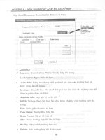
4. Define and assign frame sections
Define the beam, exterior column, and interior column sections
Menu: Define > Frame Sections > Add Rectangular
Note: Don’t forget to change the units to kips-in before specifying member dimensions
beam exterior column interior column
After the member sections are defined, select members with common sections and assign the
respective section from menu: Assign > Frame > Sections. After assigning the sections, 2D/3D
Extruded shape of the members can be seen from Menu: View > Set Elements > Extruded shape or
using the shortcut menu button
.
After assignment of member sections 2D Extruded view