LRFD pre-stressed beam.mcd
Bạn đang xem bản rút gọn của tài liệu. Xem và tải ngay bản đầy đủ của tài liệu tại đây (264.74 KB, 71 trang )
LRFD pre-stressed beam.mcd
7/1/2003 1 of 71
Number of Spans =
spans 1:= n 0 spans 1−..:= n2 0 1..:=
Which span is used in design =
comp1 1:=
Length of all spans (ft) =
L
n
100:=
Should the haunch depth be used in calculations (yes or no) =
ha_dec "yes":=
Depress point to use for draped strands =
depress 0.4:=
Number of span points calculations shall be done to =
(Please choose only an even number of points)
sp 20:= ns10 0 10..:=
Interior or Exterior beam used in design (intput "int" or "ext") =
aa "int":=
Beam Data
mp 10:=
Beam length (ft) =
length 100:=
Composite slab strength (ksi) =
fc 4:=
Concrete unit weight (kcf) =
γc 0.150:=
Initial strength of concrete (ksi) =
fci 6:=
Final Strength of concrete (ksi) =
fcf 8:=
Modulus of beam concrete based on final (ksi) =
Ec 33000 γc
1.5
⋅ fcf⋅:= Ec 5422.453=
Modulus of slab concrete (ksi) =
Esl 33000 γc
1.5
⋅ fc⋅:= Esl 3834.254=
LRFD pre-stressed beam.mcd
7/1/2003 2 of 71
bwt 0.822=
Beam weight (k/ft) =
fwt 20=
Width of top flange (in) =
Inc 260730=
Section inertia (in^2) =
h 54=
Total beam depth (in) =
yb 24.73=
Distance from bottom to cg (in) =
web 8=
Web thickness (in) =
Area 789=
Beam area (in^2) =
a5 0:=
Web (in) =
a4 0:=
Bottom Flange (in) =
type 4:=
a3 0:=
Top flange (in) =
a2 0:=
Depth (in) =
a1 0:=
Width (in) =
8 = IDOT 36 INCH
9 = IDOT 42 INCH
10 = IDOT 48 INCH
11 = IDOT 54 INCH
12 = Box
1 = AASHTO TYPE I
2 = AASHTO TYPE II
3 = AASHTO TYPE III
4 = AASHTO TYPE IV
5 = BT54
6 = BT63
7 = BT72
Box Beam dimensions (if no box set to zero)
Beam type to use
LRFD pre-stressed beam.mcd
7/1/2003 3 of 71
transfer 36=transfer 60 Strand_diameter⋅:=
Transfer length = 60*bd
Strand_type "LL"=Strand_type strand
s_type 5,
:=
Strand_strength 270=Strand_strength strand
s_type 4,
:=
Strand_weight 0.745=Strand_weight strand
s_type 3,
:=
Strand_area 0.217=Strand_area strand
s_type 2,
:=
Strand_diameter 0.6=Strand_diameter strand
s_type 1,
:=
Strand_description "6/10-270k-LL"=Strand_description strand
s_type 0,
:=
s_type 1:=
Strand Type to use
strand
PICK Description DIAMETER AREA WEIGHT PER LENGTH Fpu STEEL TYPE
TYPE english in in^2 lb/ft ksi
0 6/10-270k 0.6000 0.2170 0.7446 270 SR
1 6/10-270k-LL 0.6000 0.2170 0.7446 270 LL
2 9/16-270k 0.5625 0.1920 0.6588 270 SR
3 9/16-270k-LL 0.5625 0.1920 0.6588 270 LL
4 1/2-270k 0.5000 0.1530 0.5250 270 SR
5 1/2-270k-LL 0.5000 0.1530 0.5250 270 LL
6 1/2-270k-SP 0.5000 0.1670 0.5730 270 LL
7 7/16-270k 0.4375 0.1150 0.3946 270 SR
8 7/16-270k-LL 0.4375 0.1150 0.3946 270 LL
9 3/8-270k 0.3750 0.0800 0.2745 270 SR
10 3/8-270k-LL 0.3750 0.0800 0.2745 270 LL
:=
Strand pattern Data
LRFD pre-stressed beam.mcd
7/1/2003 4 of 71
fwt 20=
Width of top flange of beam (in) =
max_span 100=max_span length:=
Max span length (ft) =
(for ETFW)
bwt 0.822=
Beam weight per foot (k/ft) =
ha 4.5=ha if ha_dec "yes"= haunch, 0,( ):=haunch 4.5=haunch tstw slab−:=
Haunch Selection
tstw 12.75:=
Top slab to top beam (in) =
RF 1.0:=
Multiple presence factor =
lane_width 10:=
Width of one lane (ft) =
beams 5:=
Number of beams =
wear 0.025:=
Wearing surface (ksf) =
ts slab:=slab 8.25:=
Slab thickness (ft) =
bs 8:=
Beam spacing (ft) =
oto 40.5:=
Out to out width (ft) =
General Information
Calculations of Dead Loads, non-composite and composite
LRFD pre-stressed beam.mcd
7/1/2003 5 of 71
gt .5:=
If the user so desires, you may adjust the deck weight for the deck grooving, just enter the depth of
grooving. Enter a positive value for an increased thickness, and enter a negative value for an decreased
thickness. This adjustment in really not necessary at all, and the user may set the value equal to 0.
sipd 0.5:=
Amount of deflection in SIP form (in) =
vald 2:=
Depth of valley in SIP form (in) =
sipw 3:=
SIP form weight (psf) =
If you do not wish to use any of the optional loads then simply set the values to zero. If SIP metal forms will be
used then the first three should probably be used. However, it is most certanly not necessary to adjust for the
deck grooving.
Optional Loads
ndia 2:=
Number of Diaphragms (k) =
Note: Program assumes diaphragms are point loads at
equal spaces over the length of the beam.
wdia 1.664:=
Weight of Diaphragms (k) =
Diaphragm Data
nmed 0:=
Number of barriers =
median 0:=
Median barrier weight (k/ft) =
med_width 0:=
Median barrier width (ft) =
MEDIAN BARRIER DATA
npar 2:=
Number of parapet's =
railwt 0.5:=
Rail weight per foot (k/ft) =
outside 1.0:=
Rail width on outside (ft) =
RAIL OR PARAPET DATA
LRFD pre-stressed beam.mcd
7/1/2003 6 of 71
DLc 0.417=DLc
roadway wear⋅ railwt npar⋅+ median nmed⋅+
beams
groov+:=
roadway 38.5=roadway oto npar outside⋅− med_width−:=
Roadway width (ft) =
COMPOSITE DL (DW)
DLnc 1.047=DLnc max
oto
slab
12
⋅
beams
γc⋅
bs
slab
12
⋅ γc⋅
optional+:=
NON COMPOSITE DL (excluding beam weight) (DLnc) (DC)
Final Composite and Non-Composite Loads
optional 0.212=optional filler SIP+ valley+ wdefl+:=
Total optional loads (k/ft) =
groov 0.025=groov bs
gt
24
⋅ γc⋅:=
Deck grooving (k/ft) =
(Say that the deck
grooving adds 1/4"
in depth)
wdefl 0.02=wdefl bs
fwt
12
−
sipd
24
⋅ γc⋅:=
Weight from deflections (k/ft) =
(this assumes that the SIP form
will deflect, adding about 1/2"
depth for every 1" of deflection)
valley 0.079=valley bs
fwt
12
−
vald
24
⋅ γc⋅:=
Concrete in valley of SIP form (k/ft) =
(say each inch of valley is equal to
1/2" of concrete depth)
SIP 0.019=SIP bs
fwt
12
−
sipw
1000
⋅:=
SIP form (k/ft) =
say (3 psf)
filler 0.094=filler
fwt haunch⋅
144
γc⋅:=
Filler weight (k/ft) =
LRFD pre-stressed beam.mcd
7/1/2003 7 of 71
Unit Load for Diaphragm, to be used only for Deflections (the actual
point loads will be used for shear and moment)
dwt
wdia ndia⋅
length
:= dwt 0.033=
Unit weight to be used in in the calculation of Non-Composite DL Deflection
w_defl DLnc
railwt npar⋅ median nmed⋅+
beams
+ dwt+:=
LRFD pre-stressed beam.mcd
7/1/2003 8 of 71
ETFW 96=ETFW ETFW_ext aa "ext"=if
ETFW_int otherwise
:=
Effective flange width used in design
ETFW_int 96=ETFW_ext min
etfw1
etfw2
etfw3
:=
etfw3 51=etfw3
oto beams 1−( ) bs⋅−
2
12⋅:=
etfw2 59.5=etfw2 6 slab⋅
fwt
2
+:=
etfw1 150=etfw1
length
8
12⋅:=
1. 1/8 Effective Span
2. 6*ts + B ; B = largter of the web thickness or 1/2 top flange width
3. overhang
Exterior - 1/2 effective width of adjacent interior beam plus the smaller of the following
ETFW_int 96=ETFW_int min
etfw1
etfw2
etfw3
:=
etfw3 109=etfw3 12 slab⋅
fwt
2
+:=
etfw2 96=etfw2 bs 12⋅:=
etfw1 300=etfw1
length
4
12⋅:=
1. 1/4 span length
2. center to center beams
3. 12*T+B ; B = larger of the web thickness or 1/2 top flange width
Interior - smaller of the following
Effective flange width (LRFD 4.6.2.6.1) (use the smaller of interior or exterior)
LRFD pre-stressed beam.mcd
7/1/2003 9 of 71
Section Diagram
40 20 0 20 40 60 80
0
10
20
30
40
50
60
70
Section
beam
xa 1,
xh
xhn 1,
xe
xhn 1,
beam
xa 0,
xh
xhn 0,
, xe
xhn 0,
,
LRFD pre-stressed beam.mcd
7/1/2003 10 of 71
Composite moment of inertia (in^t) =
Ic Inc
b ts
3
⋅
12
+ Area yb ybc−( )
2
⋅+ b ts⋅ yts
ts
2
−
2
⋅+:=
Ic 734265.849=
Composite Section Modulus
Section modulus bottom of beam (in^3) =
Sbc
Ic
ybc
:= Sbc 18147.259=
Section modulus top beam (in^3) =
Stb
Ic
ytb
:= Stb 54235.51=
Section modulus top concrete (in^3) =
Stc
Ic
yts
1
η
⋅:= Stc 39500.538=
Non-Composite Section Modulus
Section modulus bottom of beam (in^3) =
Sb
Inc
yb
:= Sb 10543.065=
Section modulus top beam (in^3) =
St
Inc
h yb−
:= St 8907.755=
Composite moment of Inertia
Effective compression slab width (in) =
ETFW 96=
Modular ratio =
η
fc
fcf
:= η 0.707=
Transformed slab width (in) =
b ETFW η⋅:= b 67.882=
Slab thickness (in) =
ts 8.25=
Composite distance from bottom to c.g. (in) =
ybc
b ts⋅ h ha+
ts
2
+
⋅ Area yb⋅+
b ts⋅ Area+
:= ybc 40.462=
Composite N.A. to top beam (in) =
ytb h ybc−:= ytb 13.538=
Composite N.A. to top slab (in) =
yts h ts+ ha+ ybc−:= yts 26.288=
LRFD pre-stressed beam.mcd
7/1/2003 11 of 71
DFM
E
0.754=DFM
E
DFM
I
e⋅:=
e 1.127=e max
0.77
de
9.1
+
1.0
:=
"OK" 1.0− de≤( ) de 5.5≤( )if
"NG" otherwise
"OK"=de 3.25=de
oto beams 1−( ) bs⋅−
2
1−:=
Range of applicibility -1.0 <= de <= 5.5
Table 4.6.2.2.2.d-1 - Exterior beam distribution factor for Moment
DFM
I
0.669=
DFM
I
0.075
bs
9.5
0.6
bs
length
0.2
⋅
kg
12 length⋅ slab
3
⋅
0.1
⋅+:=
kg 1613113.272=kg
fcf
fc
Inc Area eg
2
⋅+
( )
⋅:=
eg 33.395=eg h
ts
2
+
yb−:=
Distance from N.A. non composite beam and CL. deck (in) =
Range of applicability ; 3.5 <= S <= 16
4.5 <= ts <= 20
20 <= L <= 240
Nb >= 4
10,000 <= Kg <= 7,000,000
Table 4.6.2.2.2.b-1 - Interior beam distribution factor
lanes 3=lanes floor
roadway
12
:=
LRFD 3.6.1.1.1 - Number of design lanes
Live Load Distribution Factors
LRFD pre-stressed beam.mcd
7/1/2003 12 of 71
currently disabled
LLDFV 0.814:=
Live Load distribution factor for shear
currently disabled
LLDFM 0.660:=
Live Load distribution factor for moment
If the user wants to overide the distribution factors that have been calculated, simply enable the two
numbers below and imput the desired factor.
LLDFV 0.814=LLDFV DFV
I
aa "int"=if
DFV
E
aa "ext"=if
0 otherwise
otherwise
:=
Distribution Factor for Shear Used in Design
DFV
E
0.814=DFV
E
DFV
I
e⋅:=
e 1=e max
0.6
de
10
+
1.0
:=
Range of applicibility -1 <= de <= 5.5
Table 4.6.2.2.3b-1 - Exterior beam distribution factor for shear
DFV
I
0.814=DFV
I
0.2
bs
12
+
bs
35
2
−:=
Range of applicibility: 3.5 <= S <= 16
20 <= L <= 240
4.5 <= ts <= 12
10000 <= kg <= 7,000,000
Nb >= 4.0
Table 4.6.2.2.3.a-1 - Interior beam distribution factor for shear
LLDFM 0.669=LLDFM DFM
I
aa "int"=if
DFM
E
aa "ext"=if
0 otherwise
otherwise
:=
Distribution Factor for Moment Used in Design
LRFD pre-stressed beam.mcd
7/1/2003 13 of 71
fft 0.537−=
Tension (ksi) =
fc3 3.2=fc3 0.4 fcf⋅:=
Compression (ksi) =Case III 50%PS + 50%DL + LL
fft 0.537−=
Tension (ksi) =
fc2 3.6=fc2 0.45 fcf⋅:=
Compression (ksi) =Case II PS + DL
fft 0.537−=fft 0.19− fcf⋅:=
Tension (ksi) =
fc1 4.8=fc1 0.6 fcf⋅:=
Compression (ksi) =Case I full PS + DL + LL
At final conditions 5.9.4.2
Tensiion (ksi) =
5.9.4.1.2
fit 0.539−=fit 0.22− fci⋅:=
fic 3.6=fic 0.6 fci⋅:=
Compression (ksi) =
5.9.4.1.1
At release 5.9.4.1
ALLOWABLE STRESS IN CONCRETE
LRFD pre-stressed beam.mcd
7/1/2003 14 of 71
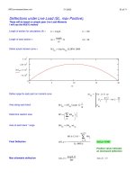
Simple Span Shear and Moment
Span length (ft) =
length 100=
Data range (ft) =
rg
ns10
j1
j
length
j
10
⋅←
j 0 10..∈for
j1
ns10
:=
Beam Weight (k/ft) =
bwt 0.822=
Self weight Moment at tenth points (k*ft) =
Mself
ns10
bwt rg
ns10
⋅
2
length rg
ns10
−
( )
⋅:=
Self weight Shear (k) =
Vself
ns10
bwt
length
2
rg
ns10
−
⋅:=
Non composite moment (k*ft) =
Mnonc
ns10
DLnc rg
ns10
⋅
2
length rg
ns10
−
( )
⋅:=
Non composite shear (k) =
Vnonc
ns10
DLnc
length
2
rg
ns10
−
⋅:=
LRFD pre-stressed beam.mcd
7/1/2003 15 of 71
Vd
0
0
1
2
3
4
5
6
7
8
9
10
1.664
1.664
1.664
1.664
0
0
0
-1.664
-1.664
-1.664
-1.664
=
Shear from
Diaphragm (k)
Md
0
0
1
2
3
4
5
6
7
8
9
10
0
16.64
33.28
49.92
55.467
55.467
55.467
49.92
33.28
16.64
0
=
Moment from
Diaphragm (k*ft)
Vd
ns10
ns11
Vd1
ns10 ns11,
∑
:=
Vd1
ns10 ns11,
P bd
ns11
⋅
length
rg
ns10
ad
ns11
<if
P bd
ns11
⋅
length
P− otherwise
:=
Shear at point of load (k) =
Md
ns10
ns11
Md1
ns10 ns11,
∑
:=
Md1
ns10 ns11,
P bd
ns11
⋅ rg
ns10
⋅
length
rg
ns10
ad
ns11
<if
P bd
ns11
⋅ rg
ns10
⋅
length
P rg
ns10
ad
ns11
−
( )
⋅− otherwise
:=
Moment at point of load (k*ft) =
bd
66.667
33.333
=bd
ns11
length ad
ns11
−:=
Definition of variable "b" =
ad
33.333
66.667
=ad
ns11
length
ndia 1+
ns11 1+( )⋅:=
Definition of variable "a" =
rg
ns10
Range for variable "x" =
P 1.664=P wdia:=
Load for diaphragm (k) =
ns11 0 ndia 1− ndia 0≠if
0 otherwise
..:=
Shear and Moment from Diaphragm
LRFD pre-stressed beam.mcd
7/1/2003 16 of 71
Moment and Shear, Generated by DL on the Composite Section.
This generator is capable of handling from 1 to 10 spans, and is capable of returning values for continuous
sections. This is done by moment distribution. The values returned are SL.
Use a unit load "w" = 1.0
unit DLc:= unit 0.417=
column 0 = span point
column 1 = moment
column 2 = shear
Based on continuous section, constant inertia.
1 1.2 1.4 1.6 1.8
0
500
1000
mc
n8
1
n8
sp
+
disp
0 1 2
0
1
2
3
4
5
6
7
8
9
10
11
12
13
14
15
16
17
18
19
20
21
22
23
24
25
26
27
28
29
30
31
32
33
34
35
36
37
38
39
1 0 20.875
1.1 187.875 16.7
1.2 334 12.525
1.3 438.375 8.35
1.4 501 4.175
1.5 521.875 0
1.6 501 -4.175
1.7 438.375 -8.35
1.8 334 -12.525
1.9 187.875 -16.7
2 0 -20.875
=
1 1.2 1.4 1.6 1.8
40
20
0
20
40
vc
n8
1
n8
sp
+
LRFD pre-stressed beam.mcd
7/1/2003 17 of 71
Notes on Live Load:
The HL-93 LL shall be used as described in 3.6.1.2 (LRFD)
The Design Lane: The design lane shall consist of a load of 0.640 k/ft uniformaly distributed in the longitudinal direction.
Transversley the load shall be assumed to be 10 ft wide. DO NOT apply the dynamic load allowance (Impact) to the lane.
The design lane shall accompany the design truck and tandem.
The Design Truck
Design truck axal spacing from rear
The Design Tandem: The design tandem consists of a pair of 25k axles spaced 4ft apart. Apply the dynamic load
allowance to the tandem
LRFD pre-stressed beam.mcd
7/1/2003 18 of 71
Load Combinations
Combination 1: The effect of the design tandem combined with the effect of the design lane.
Combination 2: The effect of the design truck combined with the effect of the design lane.
Combination 3: For both the negative moment between points of contraflexure under a uniform load on all spans, and
reaction at interior piers only.
90% of two design trucks spaced a minimum of 50 ft between the lead axle of truck 2 and the rear
axle of truck 1.
90% the design Lane
The distance between 32 k axles shall be 14 ft.
LRFD pre-stressed beam.mcd
7/1/2003 19 of 71
Moment, SL, LLDF = 1.0 wheels, Impact included, input to tenth points
ldm
DC LOADS (non-comp) DW Loads LL + I
LOCATION self wt other (comp) M (+) M (-)
0 0.00 0.00 0.00 0.00 0.00
0.1 369.90 487.80 187.88 1070.00 0.00
0.2 657.60 870.90 334.00 1883.00 0.00
0.3 863.10 1149.29 438.38 2473.00 0.00
0.4 986.40 1311.89 501.00 2763.00 0.00
0.5 1027.50 1364.24 521.88 2846.00 0.00
0.6 986.40 1311.89 501.00 2763.00 0.00
0.7 863.10 1149.29 438.38 2473.00 0.00
0.8 657.60 870.90 334.00 1883.00 0.00
0.9 369.90 487.80 187.88 1070.00 0.00
1 0.00 0.00 0.00 0.00 0.00
Mself Mnonc mca Md( )
:=
the other loads include
slab, diaphragms (if there
are any) and any other
non-composite loads.
Shear Load, SL, LLDF = 1 wheels, Impact included, input to tenth points
ldv
DC LOADS (non-comp) DW Loads LL + I
LOCATION self wt other (comp) V (+) V (-)
0 41.10 54.02 20.88 120.00 0.00
0.1 32.88 43.54 16.70 105.00 -6.00
0.2 24.66 33.07 12.53 90.00 -14.00
0.3 16.44 22.60 8.35 75.00 -23.00
0.4 8.22 10.47 4.18 61.00 -35.00
0.5 0.00 0.00 0.00 48.00 -48.00
0.6 -8.22 -10.47 -4.18 35.00 -61.00
0.7 -16.44 -22.60 -8.35 23.00 -75.00
0.8 -24.66 -33.07 -12.53 13.00 -90.00
0.9 -32.88 -43.54 -16.70 6.00 -105.00
1 -41.10 -54.02 -20.88 0.00 -120.00
Vself Vnonc vca Vd( )
:=
the other loads include
slab, diaphragms (if there
are any) and any other
non-composite loads.
LRFD pre-stressed beam.mcd
7/1/2003 20 of 71
Expand area for moment and shear iterations, Also LLDF is applied here
Service I loads (moment)
full
SI1
SI2
SI3
SI4
SI5
SI6
SI7
SI1 SI2 SI3 SI4 SI5 SI5 SI7
DC LOADS (non-comp) DW Loads LL + I TOTAL LOADS
LOCATION self wt other (slab) (comp) M (+) M (-) M (+) M (-)
1 0.00 0.00 0.00 0.00 0.00 0.00 0.00
1.05 184.95 243.90 93.94 357.89 0.00 880.68 522.79
1.1 369.90 487.80 187.88 715.78 0.00 1761.35 1045.57
1.15 513.75 679.35 260.94 987.70 0.00 2441.74 1454.04
1.2 657.60 870.90 334.00 1259.63 0.00 3122.13 1862.50
1.25 760.35 1010.09 386.19 1456.97 0.00 3613.61 2156.63
1.3 863.10 1149.29 438.38 1654.31 0.00 4105.08 2450.77
1.35 924.75 1230.59 469.69 1751.31 0.00 4376.34 2625.03
1.4 986.40 1311.89 501.00 1848.31 0.00 4647.60 2799.29
1.45 1006.95 1338.07 511.44 1876.07 0.00 4732.53 2856.45
1.5 1027.50 1364.24 521.88 1903.83 0.00 4817.45 2913.62
1.55 1006.95 1338.07 511.44 1876.07 0.00 4732.53 2856.45
1.6 986.40 1311.89 501.00 1848.31 0.00 4647.60 2799.29
1.65 924.75 1230.59 469.69 1751.31 0.00 4376.34 2625.03
1.7 863.10 1149.29 438.38 1654.31 0.00 4105.08 2450.77
1.75 760.35 1010.09 386.19 1456.97 0.00 3613.61 2156.63
1.8 657.60 870.90 334.00 1259.63 0.00 3122.13 1862.50
1.85 513.75 679.35 260.94 987.70 0.00 2441.74 1454.04
1.9 369.90 487.80 187.88 715.78 0.00 1761.35 1045.57
1.95 184.95 243.90 93.94 357.89 0.00 880.68 522.79
2 0.00 0.00 0.00 0.00 0.00 0.00 0.00
ldm_f
:=
LRFD pre-stressed beam.mcd
7/1/2003 21 of 71
Service III loads (moment)
SIII1
SIII2
SIII3
SIII4
SIII5
SIII6
SIII7
SIII1 SIII2 SIII3 SIII4 SIII5 SIII5 SIII7
DC LOADS (non-comp) DW Loads LL + I TOTAL LOADS
LOCATION self wt other (slab) (comp) M (+) M (-) M (+) M (-)
1 0.00 0.00 0.00 0.00 0.00 0.00 0.00
1.05 184.95 243.90 93.94 286.31 0.00 809.10 522.79
1.1 369.90 487.80 187.88 572.62 0.00 1618.20 1045.57
1.15 513.75 679.35 260.94 790.16 0.00 2244.20 1454.04
1.2 657.60 870.90 334.00 1007.71 0.00 2870.20 1862.50
1.25 760.35 1010.09 386.19 1165.58 0.00 3322.21 2156.63
1.3 863.10 1149.29 438.38 1323.45 0.00 3774.22 2450.77
1.35 924.75 1230.59 469.69 1401.05 0.00 4026.08 2625.03
1.4 986.40 1311.89 501.00 1478.65 0.00 4277.94 2799.29
1.45 1006.95 1338.07 511.44 1500.86 0.00 4357.31 2856.45
1.5 1027.50 1364.24 521.88 1523.07 0.00 4436.68 2913.62
1.55 1006.95 1338.07 511.44 1500.86 0.00 4357.31 2856.45
1.6 986.40 1311.89 501.00 1478.65 0.00 4277.94 2799.29
1.65 924.75 1230.59 469.69 1401.05 0.00 4026.08 2625.03
1.7 863.10 1149.29 438.38 1323.45 0.00 3774.22 2450.77
1.75 760.35 1010.09 386.19 1165.58 0.00 3322.21 2156.63
1.8 657.60 870.90 334.00 1007.71 0.00 2870.20 1862.50
1.85 513.75 679.35 260.94 790.16 0.00 2244.20 1454.04
1.9 369.90 487.80 187.88 572.62 0.00 1618.20 1045.57
1.95 184.95 243.90 93.94 286.31 0.00 809.10 522.79
2 0.00 0.00 0.00 0.00 0.00 0.00 0.00
0 0.00 0.00 0.00 0.00 0.00 0.00 0.00
full
:=
LRFD pre-stressed beam.mcd
7/1/2003 22 of 71
Strength I loads (moment)
Maximum 1.25*DW + 1.5*DW + 1.75*(LL + IM)
Minimum 0.9*DC + 0.65*DW + 1.75*(LL + IM)
The loads shown in the DL columns reflect the values from Service I. The appropriate load combination (max or min) is
shown in the total loads columns. The minimum load factors for dead load are used when dead load and future wearing
survace stresses are of opposite sign to that of the live load.
STI1
STI2
STI3
STI4
STI5
STI6
STI7
STI1 STI2 STI3 STI4 STI5 STI6 STI7
DC LOADS (non-comp) DW Loads LL + I TOTAL LOADS
LOCATION self wt other (slab) (comp) M (+) M (-) M (+) M (-)
1 0.00 0.00 0.00 0.00 0.00 0.00 0.00
1.05 184.95 243.90 93.94 357.89 0.00 1303.27 0.00
1.1 369.90 487.80 187.88 715.78 0.00 2606.55 0.00
1.15 513.75 679.35 260.94 987.70 0.00 3611.26 0.00
1.2 657.60 870.90 334.00 1259.63 0.00 4615.98 0.00
1.25 760.35 1010.09 386.19 1456.97 0.00 5342.04 0.00
1.3 863.10 1149.29 438.38 1654.31 0.00 6068.10 0.00
1.35 924.75 1230.59 469.69 1751.31 0.00 6463.50 0.00
1.4 986.40 1311.89 501.00 1848.31 0.00 6858.91 0.00
1.45 1006.95 1338.07 511.44 1876.07 0.00 6981.55 0.00
1.5 1027.50 1364.24 521.88 1903.83 0.00 7104.20 0.00
1.55 1006.95 1338.07 511.44 1876.07 0.00 6981.55 0.00
1.6 986.40 1311.89 501.00 1848.31 0.00 6858.91 0.00
1.65 924.75 1230.59 469.69 1751.31 0.00 6463.50 0.00
1.7 863.10 1149.29 438.38 1654.31 0.00 6068.10 0.00
1.75 760.35 1010.09 386.19 1456.97 0.00 5342.04 0.00
1.8 657.60 870.90 334.00 1259.63 0.00 4615.98 0.00
1.85 513.75 679.35 260.94 987.70 0.00 3611.26 0.00
1.9 369.90 487.80 187.88 715.78 0.00 2606.55 0.00
1.95 184.95 243.90 93.94 357.89 0.00 1303.27 0.00
2 0.00 0.00 0.00 0.00 0.00 0.00 0.00
0 0.00 0.00 0.00 0.00 0.00 0.00 0.00
full
:=
LRFD pre-stressed beam.mcd
7/1/2003 23 of 71
Service I loads (shear)
fullv
SI1v
SI2v
SI3v
SI4v
SI5v
SI6v
SI7v
SI1 SI2 SI3 SI4 SI5 SI5 SI7
DC LOADS (non-comp) DW Loads LL + I TOTAL LOADS
LOCATION self wt other (slab) (comp) V (+) V (-) V (+) V (-)
1 41.10 54.02 20.88 97.73 0.00 213.72 115.99
1.05 36.99 48.78 18.79 91.62 -2.44 196.18 102.11
1.1 32.88 43.54 16.70 85.51 -4.89 178.64 88.24
1.15 28.77 38.31 14.61 79.41 -8.14 161.10 73.55
1.2 24.66 33.07 12.53 73.30 -11.40 143.56 58.86
1.25 20.55 27.84 10.44 67.19 -15.07 126.02 43.76
1.3 16.44 22.60 8.35 61.08 -18.73 108.48 28.66
1.35 12.33 16.54 6.26 55.38 -23.62 90.51 11.51
1.4 8.22 10.47 4.18 49.68 -28.50 72.54 -5.64
1.45 4.11 5.24 2.09 44.39 -33.80 55.82 -22.37
1.5 0.00 0.00 0.00 39.09 -39.09 39.09 -39.09
1.55 -4.11 -5.24 -2.09 33.80 -44.39 22.37 -55.82
1.6 -8.22 -10.47 -4.18 28.50 -49.68 5.64 -72.54
1.65 -12.33 -16.54 -6.26 23.62 -55.38 -11.51 -90.51
1.7 -16.44 -22.60 -8.35 18.73 -61.08 -28.66 -108.48
1.75 -20.55 -27.84 -10.44 14.66 -67.19 -44.17 -126.02
1.8 -24.66 -33.07 -12.53 10.59 -73.30 -59.67 -143.56
1.85 -28.77 -38.31 -14.61 7.74 -79.41 -73.96 -161.10
1.9 -32.88 -43.54 -16.70 4.89 -85.51 -88.24 -178.64
1.95 -36.99 -48.78 -18.79 2.44 -91.62 -102.11 -196.18
2 -41.10 -54.02 -20.88 0.00 -97.73 -115.99 -213.72
ldv_f
:=
LRFD pre-stressed beam.mcd
7/1/2003 24 of 71
Service III loads (shear)
SIII1v
SIII2v
SIII3v
SIII4v
SIII5v
SIII6v
SIII7v
SIII1 SIII2 SIII3 SIII4 SIII5 SIII5 SIII7
DC LOADS (non-comp) DW Loads LL + I TOTAL LOADS
LOCATION self wt other (slab) (comp) V (+) V (-) V (+) V (-)
1 41.10 54.02 20.88 78.18 0.00 194.17 115.99
1.05 36.99 48.78 18.79 73.30 -1.95 177.86 102.60
1.1 32.88 43.54 16.70 68.41 -3.91 161.54 89.22
1.15 28.77 38.31 14.61 63.52 -6.52 145.22 75.18
1.2 24.66 33.07 12.53 58.64 -9.12 128.90 61.14
1.25 20.55 27.84 10.44 53.75 -12.05 112.58 46.77
1.3 16.44 22.60 8.35 48.87 -14.99 96.26 32.41
1.35 12.33 16.54 6.26 44.30 -18.89 79.43 16.24
1.4 8.22 10.47 4.18 39.74 -22.80 62.61 0.06
1.45 4.11 5.24 2.09 35.51 -27.04 46.94 -15.61
1.5 0.00 0.00 0.00 31.27 -31.27 31.27 -31.27
1.55 -4.11 -5.24 -2.09 27.04 -35.51 15.61 -46.94
1.6 -8.22 -10.47 -4.18 22.80 -39.74 -0.06 -62.61
1.65 -12.33 -16.54 -6.26 18.89 -44.30 -16.24 -79.43
1.7 -16.44 -22.60 -8.35 14.99 -48.87 -32.41 -96.26
1.75 -20.55 -27.84 -10.44 11.73 -53.75 -47.10 -112.58
1.8 -24.66 -33.07 -12.53 8.47 -58.64 -61.79 -128.90
1.85 -28.77 -38.31 -14.61 6.19 -63.52 -75.50 -145.22
1.9 -32.88 -43.54 -16.70 3.91 -68.41 -89.22 -161.54
1.95 -36.99 -48.78 -18.79 1.95 -73.30 -102.60 -177.86
2 -41.10 -54.02 -20.88 0.00 -78.18 -115.99 -194.17
0 0.00 0.00 0.00 0.00 0.00 0.00 0.00
fullv
:=
LRFD pre-stressed beam.mcd
7/1/2003 25 of 71
Strength I loads (shear)
Maximum 1.25*DC + 1.5*DW + 1.75*(LL + IM)
Minimum 0.9*DC + 0.65*DW + 1.75*(LL + IM)
The loads shown in the DL columns reflect the values from Service I. The appropriate load combination (max or min) is
shown in the total loads columns. The minimum load factors for dead load are used when dead load and future wearing
surface stresses are of opposite sign to that of the live load.
STI1v
STI2v
STI3v
STI4v
STI5v
STI6v
STI7v
STI1 STI2 STI3 STI4 STI5 STI6 STI7
DC LOADS (non-comp) DW Loads LL + I TOTAL LOADS
LOCATION self wt other (slab) (comp) V (+) V (-) V (+) V (-)
1 41.10 54.02 20.88 97.73 0.00 321.23 0.00
1.05 36.99 48.78 18.79 91.62 -2.44 295.73 85.13
1.1 32.88 43.54 16.70 85.51 -4.89 270.23 71.09
1.15 28.77 38.31 14.61 79.41 -8.14 244.73 55.62
1.2 24.66 33.07 12.53 73.30 -11.40 219.23 40.15
1.25 20.55 27.84 10.44 67.19 -15.07 193.73 23.97
1.3 16.44 22.60 8.35 61.08 -18.73 168.22 7.79
1.35 12.33 16.54 6.26 55.38 -23.62 142.39 -11.28
1.4 8.22 10.47 4.18 49.68 -28.50 116.56 -30.35
1.45 4.11 5.24 2.09 44.39 -33.80 92.49 -49.38
1.5 0.00 0.00 0.00 39.09 -39.09 68.41 -68.41
1.55 -4.11 -5.24 -2.09 33.80 -44.39 49.38 -92.49
1.6 -8.22 -10.47 -4.18 28.50 -49.68 30.35 -116.56
1.65 -12.33 -16.54 -6.26 23.62 -55.38 11.28 -142.39
1.7 -16.44 -22.60 -8.35 18.73 -61.08 -7.79 -168.22
1.75 -20.55 -27.84 -10.44 14.66 -67.19 -24.68 -193.73
1.8 -24.66 -33.07 -12.53 10.59 -73.30 -41.57 -219.23
1.85 -28.77 -38.31 -14.61 7.74 -79.41 -56.33 -244.73
1.9 -32.88 -43.54 -16.70 4.89 -85.51 -71.09 -270.23
1.95 -36.99 -48.78 -18.79 2.44 -91.62 -85.13 -295.73
2 -41.10 -54.02 -20.88 0.00 -97.73 0.00 -321.23
0 0.00 0.00 0.00 0.00 0.00 0.00 0.00
fullv
:=