Volume 3 Mechanical Engineers’ Handbook Third Edition Manufacturing and Management doc
Bạn đang xem bản rút gọn của tài liệu. Xem và tải ngay bản đầy đủ của tài liệu tại đây (15.06 MB, 833 trang )
Volume 3
Mechanical Engineers’ Handbook
Third Edition
Manufacturing
and Management
Edited by
Myer Kutz
JOHN WILEY & SONS, INC.
This book is printed on acid-free paper.
ࠗϱ
Copyright ᭧ 2006 by John Wiley & Sons, Inc. All rights reserved.
Published by John Wiley & Sons, Inc., Hoboken, New Jersey.
Published simultaneously in Canada.
No part of this publication may be reproduced, stored in a retrieval system, or transmitted in any form
or by any means, electronic, mechanical, photocopying, recording, scanning, or otherwise, except as
permitted under Section 107 or 108 of the 1976 United States Copyright Act, without either the prior
written permission of the Publisher, or authorization through payment of the appropriate per-copy fee
to the Copyright Clearance Center, Inc., 222 Rosewood Drive, Danvers, MA 01923, (978) 750-8400,
fax (978) 750-4470, or on the web at www.copyright.com. Requests to the Publisher for permission
should be addressed to the Permissions Department, John Wiley & Sons, Inc., 111 River Street,
Hoboken, NJ 07030, (201) 748-6011, fax (201) 748-6008, or online at go/
permission.
Limit of Liability/Disclaimer of Warranty: While the publisher and author have used their best efforts
in preparing this book, they make no representations or warranties with respect to the accuracy or
completeness of the contents of this book and specifically disclaim any implied warranties of
merchantability or fitness for a particular purpose. No warranty may be created or extended by sales
representatives or written sales materials. The advice and strategies contained herein may not be
suitable for your situation. The publisher is not engaged in rendering professional services, and you
should consult a professional where appropriate. Neither the publisher nor author shall be liable for
any loss of profit or any other commercial damages, including but not limited to special, incidental,
consequential, or other damages.
For general information on our other products and services, please contact our Customer Care
Department within the United States at (800) 762-2974, outside the United States at (317) 572-3993
or fax (317) 572-4002.
Wiley also publishes its books in a variety of electronic formats. Some content that appears in print
may not be available in electronic books. For more information about Wiley products, visit our web
site at www.wiley.com.
Library of Congress Cataloging-in-Publication Data:
Mechanical engineers’ handbook/edited by Myer Kutz.—3rd ed.
p. cm.
Includes bibliographical references and index.
ISBN-13 978-0-471-44990-4
ISBN-10 0-471-44990-3 (cloth)
1. Mechanical engineering—Handbooks, manuals, etc. I. Kutz, Myer.
TJ151.M395 2005
621—dc22
2005008603
Printed in the United States of America.
10987654321
To Alan and Nancy, now and forever
vii
Contents
Preface ix
Vision Statement xi
Contributors xiii
PART 1 MANUFACTURING 1
1. Product Design for Manufacturing and Assembly (DFM&A) 3
Gordon Lewis
2. Achieving Enterprise Goals with New Process Technology 22
Steve W. Tuszynski
3. Classification Systems 68
Dell K. Allen
4. Production Planning 110
Bhaba R. Sarker, Dennis B. Webster, and Thomas G. Ray
5. Production Processes and Equipment 173
Magd E. Zohdi, William E. Biles, and Dennis B. Webster
6. Metal Forming, Shaping, and Casting 245
Magd E. Zohdi and William E. Biles
7. Mechanical Fasteners 286
Murray J. Roblin, updated by Anthony Luscher
8. Statistical Quality Control 315
Magd E. Zohdi
9. Computer-Integrated Manufacturing 328
William E. Biles and Magd E. Zohdi
10. Material Handling 349
William E. Biles, John S. Usher, and Magd E. Zohdi
11. Coatings and Surface Engineering: Physical Vapor Deposition 396
Allan Matthews and Suzanne L. Rohde
12. Product Design and Manufacturing Processes for Sustainability 414
I. S. Jawahir, P. C. Wanigarathne, and X. Wang
PART 2 MANAGEMENT, FINANCE, QUALITY, LAW,
AND RESEARCH 445
13. Managing Projects in Engineering Organizations Using Interorganizational
Teams 447
Karen L. Higgins and Joseph A. Maciarello
14. Managing People 484
Hans J. Thamain
viii Contents
15. Finance and the Engineering Function 505
William Brett
16. Detailed Cost Estimating 531
Rodney D. Stewart
17. Investment Analysis 564
Byron W. Jones
18. Total Quality Management, Six Sigma, and Continuous Improvement 583
Jack B. ReVelle and Robert Alan Kemerling
19. Registrations, Certifications, and Awards 616
Jack B. ReVelle and Cynthia M. Sabelhaus
20. Safety Engineering 639
Jack B. ReVelle
21. What the Law Requires of the Engineer 701
Alvin S. Weinstein, and Martin S. Chizek
22. Patents 725
David A. Burge and Benjamin D. Burge
23. Electronic Information Resources: Your Online Survival Guide 758
Robert N. Schwarzwalder, Jr.
24. Sources of Mechanical Engineering Information 777
Fritz Dusold and Myer Kutz
Index 785
ix
Preface
The third volume of the Third Edition of the Mechanical Engineers’ Handbook comprises
two parts: Manufacturing and Management. Each part contains 12 chapters. Contributors
include business owners, consultants, lawyers, librarians, and academics from all around the
United States.
Part 1 opens with a chapter from the second edition on Product Design for Manufac-
turing and Assembly (DFM&A). The centerpiece of Part 1 includes the chapters that in
earlier editions of the handbook have been called ‘‘the handbook within the handbook.’’
Developed by a team at Louisiana State University and the University of Louisville, these
six chapters, which have been updated, span manufacturing topics from production planning,
production processes and equipment, metal forming, shaping, and casting, statistical quality
control, computer-integrated manufacturing, to material handling. The chapter on classifi-
cation systems remains unchanged from earlier editions; the chapter on mechanical fasteners
has been revised extensively. Part 1 has three chapters entirely new to the handbook: a chapter
on physical vapor deposition, one on environmentally conscious manufacturing, and one on
a new approach to dealing with process technology in the context of design, tooling, man-
ufacturing, and quality engineering. The latter chapter is indicative of how much contributors
can give of themselves. Its content is the lifeblood of its author’s consulting practice.
Part 2 covers a broad array of topics. The 12 chapters can be broken down into four
groups. The first two chapters cover project and people management. The first of these
chapters, on project management, deals with a subject that has appeared in previous editions,
but the chapter is entirely new, to reflect advances in this field. The people management
chapter has been revised. The following three chapters deal with fundamentals of financial
management and are unchanged. The next three chapters, contributed by a team led by Jack
ReVelle, treat a set of management issues, including Total Quality Management; registrations,
certifications, and awards; and safety engineering. Two chapters cover legal issues of interest
to engineers, including patents. The final two chapters cover online and print information
sources useful to mechanical engineers in their daily work. The chapter on online sources
is a new version of the chapter that appeared originally in 1998.
xi
Vision for the Third Edition
Basic engineering disciplines are not static, no matter how old and well established they are.
The field of mechanical engineering is no exception. Movement within this broadly based
discipline is multidimensional. Even the classic subjects on which the discipline was founded,
such as mechanics of materials and heat transfer, continue to evolve. Mechanical engineers
continue to be heavily involved with disciplines allied to mechanical engineering, such as
industrial and manufacturing engineering, which are also constantly evolving. Advances in
other major disciplines, such as electrical and electronics engineering, have significant impact
on the work of mechanical engineers. New subject areas, such as neural networks, suddenly
become all the rage.
In response to this exciting, dynamic atmosphere, the Mechanical Engineers’Handbook
is expanding dramatically, from one volume to four volumes. The third edition not only is
incorporating updates and revisions to chapters in the second edition, which was published
in 1998, but also is adding 24 chapters on entirely new subjects as well, incorporating updates
and revisions to chapters in the Handbook of Materials Selection, which was published in
2002, as well as to chapters in Instrumentation and Control, edited by Chester Nachtigal
and published in 1990.
The four volumes of the third edition are arranged as follows:
Volume I: Materials and Mechanical Design—36 chapters
Part 1. Materials—14 chapters
Part 2. Mechanical Design—22 chapters
Volume II: Instrumentation, Systems, Controls, and MEMS—21 chapters
Part 1. Instrumentation—8 chapters
Part 2. Systems, Controls, and MEMS—13 chapters
Volume III: Manufacturing and Management—24 chapters
Part 1. Manufacturing—12 chapters
Part 2. Management, Finance, Quality, Law, and Research—12 chapters
Volume IV: Energy and Power—31 chapters
Part 1: Energy—15 chapters
Part 2: Power—16 chapters
The mechanical engineering literature is extensive and has been so for a considerable
period of time. Many textbooks, reference works, and manuals as well as a substantial
number of journals exist. Numerous commercial publishers and professional societies, par-
ticularly in the United States and Europe, distribute these materials. The literature grows
continuously, as applied mechanical engineering research finds new ways of designing, con-
trolling, measuring, making and maintaining things, and monitoring and evaluating technol-
ogies, infrastructures, and systems.
Most professional-level mechanical engineering publications tend to be specialized, di-
rected to the specific needs of particular groups of practitioners. Overall, however, the me-
chanical engineering audience is broad and multidisciplinary. Practitioners work in a variety
of organizations, including institutions of higher learning, design, manufacturing, and con-
xii Vision for the Third Edition
sulting firms as well as federal, state, and local government agencies. A rationale for an
expanded general mechanical engineering handbook is that every practitioner, researcher,
and bureaucrat cannot be an expert on every topic, especially in so broad and multidiscipli-
nary a field, and may need an authoritative professional summary of a subject with which
he or she is not intimately familiar.
Starting with the first edition, which was published in 1986, our intention has always
been that the Mechanical Engineers’ Handbook stand at the intersection of textbooks, re-
search papers, and design manuals. For example, we want the handbook to help young
engineers move from the college classroom to the professional office and laboratory where
they may have to deal with issues and problems in areas they have not studied extensively
in school.
With this expanded third edition, we have produced a practical reference for the me-
chanical engineer who is seeking to answer a question, solve a problem, reduce a cost, or
improve a system or facility. The handbook is not a research monograph. The chapters offer
design techniques, illustrate successful applications, or provide guidelines to improving the
performance, the life expectancy, the effectiveness, or the usefulness of parts, assemblies,
and systems. The purpose is to show readers what options are available in a particular
situation and which option they might choose to solve problems at hand.
The aim of this expanded handbook is to serve as a source of practical advice to readers.
We hope that the handbook will be the first information resource a practicing engineer
consults when faced with a new problem or opportunity—even before turning to other print
sources, even officially sanctioned ones, or to sites on the Internet. (The second edition has
been available online on knovel.com.) In each chapter, the reader should feel that he or she
is in the hands of an experienced consultant who is providing sensible advice that can lead
to beneficial action and results.
Can a single handbook, even spread out over four volumes, cover this broad, interdis-
ciplinary field? We have designed the third edition of the Mechanical Engineers’ Handbook
as if it were serving as a core for an Internet-based information source. Many chapters in
the handbook point readers to information sources on the Web dealing with the subjects
addressed. Furthermore, where appropriate, enough analytical techniques and data are pro-
vided to allow the reader to employ a preliminary approach to solving problems.
The contributors have written, to the extent their backgrounds and capabilities make
possible, in a style that reflects practical discussion informed by real-world experience. We
would like readers to feel that they are in the presence of experienced teachers and con-
sultants who know about the multiplicity of technical issues that impinge on any topic within
mechanical engineering. At the same time, the level is such that students and recent graduates
can find the handbook as accessible as experienced engineers.
xiii
Contributors
Dell K. Allen
Brigham Young University
Provo, Utah
William E. Biles
University of Louisville
Louisville, Kentucky
William Brett
New York, New York
Benjamin D. Burge
Intel Americas, Inc.
Chantilly, Virginia
David A. Burge
David A. Burge Co., L.P.A.
Cleveland, Ohio
Martin S. Chizek
Weinstein Associates International
Delray Beach, Florida
Fritz Dusold
New York, New York
Karen L. Higgins
NAVAIR Weapons Division
China Lake, California
I. S. Jawahir
University of Kentucky
Lexington, Kentucky
Byron W. Jones
Kansas State University
Manhattan, Kansas
Robert Alan Kemerling
Ethicon Endo-Surgery, Inc.
Cincinnati, Ohio
Myer Kutz
Myer Kutz Associates, Inc.
Delmar, New York
Gordon Lewis
Digital Equipment Corporation
Maynard, Massachusetts
Anthony Luscher
The Ohio State University
Columbus, Ohio
Joseph A. Maciariello
Claremont Graduate University
Claremont, California
Allan Matthews
Sheffield University
Sheffield, United Kingdom
Thomas G. Ray
Louisiana State University
Baton Rouge, Louisiana
Jack B. Revelle
ReVelle Solutions, LLC
Santa Ana, California
Murray J. Roblin
California State Polytechnic University
Pomona, California
Suzanne L. Rohde
The University of Nebraska
Lincoln, Nebraska
Cynthia M. Sabelhaus
Raytheon Missile Systems
Tucson, Arizona
Bhaba R. Sarker
Louisiana State University
Baton Rouge, Louisiana
xiv Contributors
Robert N. Schwarzwalder, Jr.
University of Hawaii at Ma¯noa
Honolulu, Hawaii
Rodney D. Stewart (deceased)
Mobile Data Services
Huntsville, Alabama
Hans J. Thamain
Bentley College
Waltham, Massachusetts
Steve W. Tuszynski
Algoryx, Inc.
Los Angeles, California
John S. Usher
University of Louisville
Louisville, Kentucky
X. Wang
University of Kentucky
Lexington, Kentucky
P. C. Wanigarathne
University of Kentucky
Lexington, Kentucky
Dennis B. Webster
Louisiana State University
Baton Rouge, Louisiana
Alvin S. Weinstein
Weinstein Associates International
Delray Beach, Florida
Magd E. Zohdi
Louisiana State University
Baton Rouge, Louisiana
Mechanical Engineers’ Handbook
PART 1
MANUFACTURING
3
CHAPTER 1
PRODUCT DESIGN FOR MANUFACTURING
AND ASSEMBLY (DFM&A)
Gordon Lewis
Digital Equipment Corporation
Maynard, Massachusetts
1 INTRODUCTION 3
2 DESIGN FOR
MANUFACTURING AND
ASSEMBLY 4
2.1 What Is DFM&A? 5
2.2 Getting the DFM&A
Process Started 12
2.3 The DFM&A Road Map 14
3 WHY IS DFM&A
IMPORTANT? 21
REFERENCES 21
1 INTRODUCTION
Major changes in product design practices are occurring in all phases of the new product
development process. These changes will have a significant impact on how all products are
designed and the development of the related manufacturing processes over the next decade.
The high rate of technology changes has created a dynamic situation that has been difficult
to control for most organizations. There are some experts who openly say that if we have
no new technology for the next five years, corporate America might just start to catch up.
The key to achieving benchmark time to market, cost, and quality is in up-front technology,
engineering, and design practices that encourage and support a wide latitude of new product
development processes. These processes must capture modern manufacturing technologies,
piece parts that are designed for ease of assembly, and parts that can be fabricated using
low-cost manufacturing processes. Optimal new product design occurs when the designs of
machines and of the manufacturing processes that produce those machines are congruent.
The obvious goal of any new product development process is to turn a profit by con-
verting raw material into finished products. This sounds simple, but it has to be done effi-
ciently and economically. Many companies do not know how much it costs to manufacture
a new product until well after the production introduction. Rule #1: The product development
team must be given a cost target at the start of the project. We will call this cost the unit
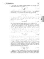
manufacturing cost (UMC) target. Rule #3: The product development team must be held
accountable for this target cost. What happened to rule #2? We’ll discuss that shortly. In the
meantime, we should understand what UMC is.
UMC
ϭ BL ϩ MC ϩ TA
where BL
ϭ burdened assembly labor rate per hour; this is the direct labor cost of labor,
benefits, and all appropriate overhead cost
MC
ϭ material cost; this is the cost of all materials used in the product
Mechanical Engineers’ Handbook: Manufacturing and Management, Volume 3, Third Edition.
Edited by Myer Kutz
Copyright
2006 by John Wiley & Sons, Inc.
4 Product Design for Manufacturing and Assembly
TA
ϭ tooling amortization; this is the cost of fabrication tools, molds and assembly
tooling, divided by the forecast volume build of the product
UMC is the direct burdened assembly labor (direct wages, benefits, and overhead) plus the
material cost. Material cost must include the cost of the transformed material plus piece part
packaging plus duty, insurance, and freight (DIF). Tooling amortization should be included
in the UMC target cost calculation, based on the forecast product life volume.
Example UMC Calculation BL
؉ MC ؉ TA
Burdened assembly labor cost calculation (BL)
Labor
BL ϭ ($18.75 ϩ 138%) ϭ $44.06/hr
Wages
ϩ
Benefits overhead
Burdened assembly labor is made up of the direct wages and benefits paid to the hourly
workers, plus a percentage added for direct overhead and indirect overhead. The overhead
added percentage will change from month to month based on plant expenses.
Material cost calculation (MC)
(Part cost
ϩ
Packaging)
ϩ
DIF
ϩ
Mat. Acq. cost
ϭ
MC ϭ ($2.45 ϩ $.16) ϩ 12% ϩ 6% ϭ
MC ϭ $2.61 ϩ $.31 ϩ $.15 ϭ $3.07
Material FOB assm. plant
Material cost should include the cost of the parts and all necessary packaging. This calcu-
lation should also include a percent adder for duty, insurance, and freight (DIF) and an adder
for the acquisition of the materials (Mat. Acq.). DIF typically is between 4 and 12% and
Mat. Acq. typically is in the range of 6 to 16%. It is important to understand the MC because
material is the largest expense in the UMC target.
Tooling amortization cost calculations (TA)
(Tool cost) # of parts
TA ϭ TC / PL
TA
ϭ $56,000/10,000 ϭ $5.60 per assembly
TC is the cost of tooling and PL is the estimated number of parts expected to be produced
on this tooling. Tooling cost is the total cost of dies and mold used to fabricate the component
parts of the new product. This also should include the cost of plant assembly fixtures and
test and quality inspection fixtures.
The question is, ‘‘How can the product development team quickly and accurately mea-
sure UMC during the many phases of the project?’’ What is needed is a tool that provides
insight into the product structure and at the same time exposes high-cost areas of the design.
2 DESIGN FOR MANUFACTURING AND ASSEMBLY
Designing for Manufacturing and Assembly (DFM&A) is a technique for reducing the cost
of a product by breaking the product down into its simplest components. All members of
the design team can understand the product’s assembly sequence and material flow early in
the design process.
DFM&A tools lead the development team in reducing the number of individual parts
that make up the product and ensure that any additional or remaining parts are easy to handle
2 Design for Manufacturing and Assembly 5
and insert during the assembly process. DFM&A encourages the integration of parts and
processes, which helps reduce the amount of assembly labor and cost. DFM&A efforts
include programs to minimize the time it takes for the total product development cycle,
manufacturing cycle, and product life-cycle costs. Additionally, DFM&A design programs
promote team cooperation and supplier strategy and business considerations at an early stage
in the product development process.
The DFM&A process is composed of two major components: design for assembly (DFA)
and design for manufacturing (DFM). DFA is the labor side of the product cost. This is the
labor needed to transform the new design into a customer-ready product. DFM is the material
and tooling side of the new product. DFM breaks the parts fabrication process down into its
simplest steps, such as the type of equipment used to produce the part and fabrication cycle
time to produce the part, and calculates a cost for each functional step in the process. The
program team should use the DFM tools to establish the material target cost before the new
product design effort starts.
Manufacturing costs are born in the early design phase of the project. Many different
studies have found that as much as 80% of a new product’s cost is set in concrete at the
first drawing release phase of the product. Many organizations find it difficult to implement
changes to their new product development process. The old saying applies: ‘‘only wet babies
want to change, and they do it screaming and crying.’’ Figure 1 is a memo that was actually
circulated in a company trying to implement a DFM&A process. Only the names have been
changed.
It is clear from this memo that neither the engineering program manager nor the man-
ufacturing program manager understood what DFM&A was or how it should be implemented
in the new product development process. It seems that their definition of concurrent engi-
neering is, ‘‘Engineering creates the design and manufacturing is forced to concur with it
with little or no input.’’ This is not what DFM&A is.
2.1 What Is DFM&A?
DFM&A is not a magic pill. It is a tool that, when used properly, will have a profound
effect on the design philosophy of any product. The main goal of DFM&A is to lower
product cost by examining the product design and structure at the early concept stages of a
new product. DFM&A also leads to improvements in serviceability, reliability, and quality
of the end product. It minimizes the total product cost by targeting assembly time, part cost,
and the assembly process in the early stages of the product development cycle.
The life of a product begins with defining a set of product needs, which are then
translated into a set of product concepts. Design engineering takes these product concepts
and refines them into a detailed product design. Considering that from this point the product
will most likely be in production for a number of years, it makes sense to take time out
during the design phase to ask, ‘‘How should this design be put together?’’ Doing so will
make the rest of the product life, when the design is complete and handed off to production
and service, much smoother. To be truly successful, the DFM&A process should start at the
early concept development phase of the project. True, it will take time during the hectic
design phase to apply DFM&A, but the benefits easily justify additional time.
DFM&A is used as a tool by the development team to drive specific assembly benefits
and identify drawbacks of various design alternatives, as measured by characteristics such
as total number of parts, handling and insertion difficulty, and assembly time. DFM&A
converts time into money, which should be the common metric used to compare alternative
designs, or redesigns of an existing concept. The early DFM&A analysis provides the product
6 Product Design for Manufacturing and Assembly
Memorandum: Ajax Bowl Corporation
DATE: January 26, 1997
TO: Manufacturing Program Manager, Auto Valve Project
FROM: Engineering Program Manager, Auto Valve Project
RE: Design for Manufacturing & Assembly support for Auto Valve Project
CC: Director, Flush Valve Division
Due to the intricate design constraints placed on the Auto Valve project engineering feels they will not have the resources
to apply the Design for Manufacturing and Assembly process. Additionally, this program is strongly schedule driven. The
budget for the project is already approved as are other aspects of the program that require it to be on-time in order to
achieve the financial goals of upper management.
In the meeting on Tuesday, engineering set down the guidelines for manufacturing involvement on the Auto Valve project.
This was agreed to by several parties (not manufacturing) at this meeting.
The manufacturing folks wish to be tied early into the Auto Valve design effort:
1. This will allow manufacturing to be familiar with what is coming.
2. Add any ideas or changes that would reduce overall cost or help schedule.
3. Work vendor interface early, manufacturing owns the vendor issues when the product comes to the plant, anyways.
Engineering folks like the concept of new ideas, but fear:
1. Inputs that get pushed without understanding of all properly weighted constraints.
2. Drag on schedule due to too many people asking to change things.
3. Spending time defending and arguing the design.
PROPOSAL—Turns out this is the way we will do it.
Engineering shall on a few planned occasions address manufacturing inputs through one manufacturing person. Most
correspondence will be written and meeting time will be minimal. It is understood that this program is strongly driven by
schedule, and many cost reduction efforts are already built into the design so that the published budget can be met.
The plan for Engineering:
● When drawings are ready, Engineering Program Manager (EPM) will submit them to Manufacturing Program Manager
(MPM).
● MPM gathers inputs from manufacturing people and submits them back in writting to EPM. MPM works questions
through EPM to minimize any attention units that Engineering would have to spend.
● EPM submits suggestions to Engineering, for one quick hour of discussion/ acceptance/veto.
● EPM submits written response back to MPM and works any Design continues under ENG direction.
● When a prototype parts arrives, the EPM will allow the MPM to use it in manufacturing discussions.
● MPM will submit written document back to EPM to describe issues and recommendations.
● Engineering will incorporate any changes that they can handle within the schedule that they see fit.
Figure 1
development team with a baseline to which comparisons can be made. This early analysis
will help the designer to understand the specific parts or concepts in the product that require
further improvement, by keeping an itemized tally of each part’s effect on the whole assem-
bly. Once a user becomes proficient with a DFM&A tool and the concepts become second
nature, the tool is still an excellent means of solidifying what is by now second nature to
DFA veterans, and helps them present their ideas to the rest of the team in a common
language: cost.
DFM&A is an interactive learning process. It evolves from applying a specific method
to a change in attitude. Analysis is tedious at first, but as the ideas become more familiar
and eventually ingrained, the tool becomes easier to use and leads to questions: questions
about the assembly process and about established methods that have been accepted or ex-
isting design solutions that have been adopted. In the team’s quest for optimal design so-
lutions, the DFM&A process will lead to uncharted ways of doing things. Naturally, then,
2 Design for Manufacturing and Assembly 7
Figure 2 Key components of the DFM&A process.
the environment in which DFA is implemented must be ripe for challenging pat solutions
and making suggestions for new approaches. This environment must evolve from the top
down, from upper management to the engineer. Unfortunately, this is where the process too
often fails.
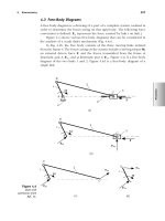
Figure 2 illustrates the ideal process for applying DFM&A. The development of any
new product must go through four major phases before it reaches the marketplace: concept,
design, development, and production. In the concept phase, product specifications are created
and the design team creates a design layout of the new product. At this point, the first design
for assembly analysis should be completed. This analysis will provide the design team with
a theoretical minimum parts count and pinpoint high-assembly areas in the design.
At this point, the design team needs to review the DFA results and adjust the design
layout to reflect the feedback of this preliminary analysis. The next step is to complete a
design for manufacturing analysis on each unique part in the product. This will consist of
developing a part cost and tooling cost for each part. It should also include doing a produc-
ibility study of each part. Based on the DFM analysis, the design team needs to make some
8 Product Design for Manufacturing and Assembly
2 end plate screws
end plate
grommet
motor
2 stand-offs
2 bushings
2 motor
screws
sensor
base
set screw
cover
4 cover
screws
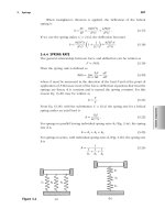
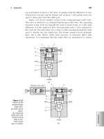
Figure 3 Proposed motor drive assembly. (From Ref. 1.)
additional adjustments in the design layout. At this point, the design team is now ready to
start the design phase of the project. The DFM&A input at this point has developed a
preliminary bill of material (BOM) and established a target cost for all the unique new parts
in the design. It has also influenced the product architecture to improve the sequence of
assembly as it flows through the manufacturing process.
The following case study illustrates the key elements in applying DFM&A. Figure 3
shows a product called the motor drive assembly. This design consists of 17 parts and
assemblies. Outwardly it looks as if it can be assembled with little difficulty. The product is
made up of two sheet metal parts and one aluminum machined part. It also has a motor
assembly and a sensor, both bought from an outside supplier. In addition, the motor drive
assembly has nine hardware items that provide other functions—or do they?
At this point, the design looks simple enough. It should take minimal engineering effort
to design and detail the unique parts and develop an assembly drawing. Has a UMC been
developed yet? Has a DFM&A analysis been performed? The DFA analysis will look at
each process step, part, and subassembly used to build the product. It will analyze the time
it takes to ‘‘get’’ and ‘‘handle’’ each part and the time it takes to insert each part in the
assembly (see Table 1). It will point out areas where there are difficulties handling, aligning,
and securing each and every part and subassembly. The DFM analysis will establish a cost
for each part and estimate the cost of fabrication tooling. The analysis will also point out
high-cost areas in the fabrication process so that changes can be made.
At this point, the DFA analysis suggested that this design could be built with fewer
parts. A review of Table 2, column 5, shows that the design team feels it can eliminate the
bushings, stand-offs, end-plate screws, grommet, cover, and cover screws. Also by replacing
the end plate with a new snap-on plastic cover, they can eliminate the need to turn the
2 Design for Manufacturing and Assembly 9
Table 1
Motor Drive Assembly
Number of parts and assemblies 19
Number of reorientation or adjustment 1
Number of special operations 2
Total assembly time in seconds 213.4
Total cost of fabrication and assembly tooling $3590
Tool amortization at 10K assemblies $ 0.36
Total cost of labor at $74.50/hr $ 4.42
Total cost of materials $ 42.44
Total cost of labor and materials $ 46.86
Total UMC $ 47.22
(reorientation) assembly over to install the end plate and two screws. Taking the time to
eliminate parts and operations is the most powerful part of performing a DFA analysis. This
is rule #2, which was left out above: DFM&A is a team sport. Bringing all members of the
new product development team together and understanding the sequence of assembly, han-
dling, and insertion time for each part will allow each team member to better understand
the function of every part.
DFM Analysis
The DFM analysis provided the input for the fabricated part cost. As an example, the base
is machined from a piece of solid aluminum bar stock. As designed, the base has 11 different
holes drilled in it and 8 of them require taping. The DFM analysis (see Table 3) shows that
it takes 17.84 minutes to machine this part from the solid bar stock. The finished machined
base costs $10.89 in lots of 1000 parts. The ideal process for completing a DFM analysis
might be as follows.
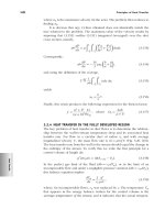
In the case of the base, the design engineer created the solid geometry in Matra Data’s
Euliked CAD system (see Fig. 4). The design engineer then sent the solid database as an
STL file to the manufacturing engineer, who then brought the STL file into a viewing tool
called Solid View (see Fig. 5). SolidView allowed the ME to get all the dimensioning and
geometry inputs needed to complete the Boothroyd Dewhurst design for manufacturing ma-
chining analysis of the base part. SolidView also allowed the ME to take cut sections of the
part and then step through it to insure that no producibility rules had been violated.
Today all of the major CAD supplies provide the STL file output format. There are
many new CAD viewing tools like SolidView available, costing about $500 to $1000. These
viewing tools will take STL or IGS files. The goal is to link all of the early product devel-
opment data together so each member can have fast, accurate inputs to influence the design
in its earliest stage.
In this example, it took the ME a total of 20 minutes to pull the STL files into SolidView
and perform the DFM analysis. Engineering in the past has complained that DFM&A takes
too much time and slows the design team down. The ME then analyzes the base as a die
casting part, following the producibility rule. By designing the base as a die casting, it is
possible to mold many of the part features into the part. This net shape die cast design will
reduce much of the machining that was required in the original design. The die cast part
will still require some machining. The DFM die casting analysis revealed that the base
10
Table 2 Motor Drive Assembly: Design for Assembly Analysis
12345678910111213141516 17
Name
Sub
No.
Entry
No. Type
Repeat
Count
Minimum
Items
Tool
Fetching
Time,
sec
Handling
Time,
sec
Insertion
or Op’n
Time,
sec
Total
Time,
sec
Labor
Cost,
$
Ass’y
Tool
or
Fixture
Cost,
$
Item
Cost,
$
Total
Item
Cost,
$
Manuf.
Tool
Cost,
$
Target
Cost,
$ Part Number Description
Base 1.1 Part 1 1 0 1.95 1.5 3.45 0.07 500 10.89 10.89 950 7.00 1P033-01 Add base to fixture
Bushing 1.2 Part 2 0 0 1.13 6.5 15.26 0.32 0 1.53 3.06 0 0.23 16P024-01 Add & press fit
Motor 1.3 Sub 1 1 0 7 6 13 0.27 0 18.56 18.56 0 12.00 121S021-02 Add & hold down
Motor screw 1.4 Part 2 2 2.9 1.5 9.6 25.1 0.52 0 0.08 0.16 0 0.08 112W0223-06 Add & thread
Sensor 1.5 Sub 1 1 0 5.6 6 11.6 0.24 0 2.79 2.79 0 2.79 124S223-01 Add & hold down
Set screw 1.6 Part 1 1 2.9 3 9.2 15.1 0.31 0 0.05 0.05 0 0.05 111W0256-02 Add & thread
Stand-off 1.7 Part 2 0 2.9 1.5 9.6 25.1 0.52 0 0.28 0.56 0 0.18 110W0334-07 Add & thread
End plate 1.8 Part 1 1 0 1.95 5.2 7.15 0.15 0 2.26 2.26 560 0.56 15P067-01 Add & hold down
End plate screw 1.9 Part 2 0 2.9 1.8 5.7 17.9 0.37 0 0.03 0.06 0 0.03 110W0777-04 Add & thread
Grommet 1.1 Part 1 0 0 1.95 11 12.95 0.27 0 0.12 0.03 0 0.12 116W022-08 Add & push fit
Dress wires—grommet 1.11 Oper 2 2 — — — 18.79 0.39 0 0.00 0.00 0 0.00 Library operation
Reorientation 1.12 Oper 1 0 — — 4.5 4.5 0.09 350 0.00 0.00 0 0.00 Reorient & adjust
Cover 1.13 Part 1 0 0 2.3 8.3 10.6 0.22 0 3.73 3.73 1230 1.20 2P033-01 Add
Cover screw 1.14 Part 4 0 2.9 1.8 5.7 32.9 0.68 0 0.05 0.18 0 0.05 112W128-03 Add & thread
Totals
ϭ 22 9 213.4 4.42 850 42.33 2740 24.28
UMC
ϭ 47.22
Production life volume ϭ 10,000
Annual build volume
ϭ 3000
Assm. labor rate $ /hr
ϭ $74.50
Note: The information presented in this table was developed from the Boothroyd Dewhurst DFA software program, version 8.0.
2
2 Design for Manufacturing and Assembly 11
Table 3 Machining Analysis Summary Report
Setups
Time
Minutes
Cost
$
Machine Tool Setups
Setup 0.22 0.10
Nonproductive 10.63 4.87
Machining 6.77 3.10
Tool wear — 0.31
Additional cost/part — 0.00
Special tool or fixture — 0.00
Library Operation Setups
Setup 0.03 0.02
Process 0.20 0.13
Additional cost/part — 0.03
Special tool or fixture — 0.00
Material — 2.34
Totals 17.84 10.89
Material Gen aluminum alloy
Part number 5678
Initial hardness 55
Form of workpiece Rectangular bar
Material cost, $/lb 2.75
Cut length, in. 4.000
Section height, in. 1.000
Section width, in. 2.200
Product life volume 10,000
Number of machine tool setups 3
Number of library operation setups 1
Workpiece weight, lb 0.85
Workpiece volume, cu in. 8.80
Material density, lb/cu in. 0.097
casting would cost $1.41 and the mold would cost $9050. Table 4 compares the two different
fabrication methods.
This early DFM&A analysis provides the product development team with accurate labor
and material estimates at the start of the project. It removes much of the complexity of the
assembly and allows each member of the design team to visualize every component’s func-
tion. By applying the basic principles of DFA, such as
• Combining or eliminating parts
• Eliminating assembly adjustments
• Designing part with self-locating features
• Designing parts with self-fastening features
• Facilitating handling of each part
• Eliminating reorientation of the parts during assembly
• Specifying standard parts
12 Product Design for Manufacturing and Assembly
Figure 4
the design team is able to rationalize the motor drive assembly with fewer parts and assembly
steps. Figure 6 shows a possible redesign of the original motor drive assembly. The DFM&A
analysis (Table 5) provided the means for the design team to question the need and function
of every part. As a result, the design team now has a new focus and an incentive to change
the original design.
Table 6 shows the before-and-after DFM&A results.
If the motor drive product meets its expected production life volume of 10,000 units,
the company will save $170,100. By applying principles of DFM&A to both the labor and
material on the motor drive, the design team is able to achieve about a 35% cost avoidance
on this program.
2.2 Getting the DFM&A Process Started
Management from All of the Major Disciplines Must Be on Your Side
In order for the DFM&A process to succeed, upper management must understand, accept,
and encourage the DFM&A way of thinking. They must want it. It is difficult, if not im-
possible, for an individual or group of individuals to perform this task without management
support, since the process requires the cooperation of so many groups working together. The
biggest challenge of implementing DFM&A is the cooperation of so many individuals to-
wards a common goal. This does not come naturally, especially if it is not perceived by the
leaders as an integral part of the business’s success. In many companies, management does
not understand what DFM&A is. They believe it is a manufacturing process. It is not; it is
a new product development process, which must include all disciplines (engineering, service,
program managers, and manufacturing) to yield significant results. The simplest method to
achieve cooperation between different organizations is to have the team members work in a
common location (co-located team). The new product development team needs some nur-
2 Design for Manufacturing and Assembly 13
Figure 5
Table 4
Die Cast
and
Machined
Machined
from Bar
Stock
Stock cost $2.34
Die casting $1.41
$9050 die casting tooling/10,000 $0.91
Machining time, min 3.6 17.84
Machining cost $3.09 $8.55
Total cost 5.41 $10.89
turing and stimulation to become empowered. This is an area where most companies just
don’t understand the human dynamics of building a high-performance team. Table 7 should
aid in determining whether you are working in a team environment or a work group envi-
ronment.
Many managers will say that their people are working in a team environment, but they
still want to have complete control over work assignments and time spent supporting the
team. In their mind, the team’s mission is secondary to the individual department manager’s
14 Product Design for Manufacturing and Assembly
cover
motor
2 motor
screws
sensor
set screw
base
Figure 6 Redesign of motor assembly.
goals. This is not a team; it is a work group. The essential elements of a high-performance
team are
• A clear understanding of the team’s goals (a defined set of goals and tasks assigned
to each individual team member)
• A feeling of openness, trust, and communication
• Shared decision-making (consensus)
• A well-understood problem-solving process
• A leader who legitimizes the team-building process
Management must recognize that to implement DFM&A in their organization, they must be
prepared to change the way they do things. Management’s reluctance to accept the need for
change is one reason DFM&A has been so slow to succeed in many companies. Training is
one way of bringing DFM&A knowledge to an organization, but training alone cannot be
expected to effect the change.
2.3 The DFM&A Road Map
The DFM&A Methodology (A Product Development Philosophy)
• Form a multifunctional team
• Establish the product goals through competitive benchmarking