Hilux 2015 2018 manual 1gd ftv intake exhaust he thong nap xa khi
Bạn đang xem bản rút gọn của tài liệu. Xem và tải ngay bản đầy đủ của tài liệu tại đây (4.61 MB, 114 trang )
Print-Toyota Service Information
11/3/17, 6(27 pm
Print
Exit
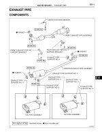
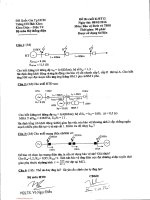
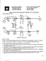
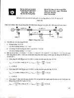
1GD-FTV INTAKE / EXHAUST EXHAUST MANIFOLD W/ TURBOCHARGER COMPONENTS
ILLUSTRATION
*A
w/ Viscous Heater
*B
for 4WD and Pre-Runner
*1
AIR CLEANER CAP SUB-ASSEMBLY WITH AIR
CLEANER HOSE
*2
AIR CLEANER CASE SUB-ASSEMBLY
/>
Page 1 of 8
Print-Toyota Service Information
11/3/17, 6(27 pm
*3
AIR CLEANER FILTER ELEMENT SUBASSEMBLY
*4
FAN SHROUD
*5
NO. 1 AIR HOSE
*6
NO. 1 ENGINE UNDER COVER ASSEMBLY
*7
NO. 1 OIL RESERVOIR BRACKET
*8
NO. 1 RADIATOR HOSE
*9
NO. 1 VISCOUS HEATER BRACKET SUBASSEMBLY
*10
NO. 2 AIR TUBE
*11
NO. 4 AIR HOSE
*12
RADIATOR RESERVOIR
*13
VANE PUMP OIL RESERVOIR ASSEMBLY
*14
*15
WATER HOSE SUB-ASSEMBLY
*16
VISCOUS HEATER WITH MAGNET CLUTCH
ASSEMBLY
FAN AND GENERATOR V BELT
*17
FAN PULLEY
*18
FLUID COUPLING ASSEMBLY
*19
NO. 1 WATER BY-PASS HOSE
*20
VISCOUS V BELT
N*m (kgf*cm, ft.*lbf): Specified torque
-
-
ILLUSTRATION
/>
Page 2 of 8
Print-Toyota Service Information
11/3/17, 6(27 pm
*A
for Cold Specification Vehicles
*B
w/o DPF
*1
EXHAUST MANIFOLD
*2
NO. 1 EGR PIPE SUB-ASSEMBLY
*3
NO. 1 WATER BY-PASS PIPE
*4
NO. 3 WATER BY-PASS PIPE
*5
*7
PCV PIPE
TURBOCHARGER STAY
*6
*8
TURBO OIL OUTLET PIPE
TURBOCHARGER SUB-ASSEMBLY
*9
COLLAR
*10
GASKET
*11
PLATE WASHER
*12
TURBO OIL OUTLET HOSE
*13
WIRE HARNESS
*14
NO. 20 WATER BY-PASS HOSE
*15
WATER HOSE
*16
STUD BOLT
/>
Page 3 of 8
Print-Toyota Service Information
11/3/17, 6(27 pm
Tightening torque for "Major areas involving
basic vehicle performance such as
moving/turning/stopping" : N*m (kgf*cm,
ft.*lbf)
●
Non-reusable part
N*m (kgf*cm, ft.*lbf): Specified torque
-
-
ILLUSTRATION
/>
Page 4 of 8
Print-Toyota Service Information
11/3/17, 6(27 pm
*A
except Cold Specification Vehicles
*B
w/ DPF
*1
EXHAUST MANIFOLD
*2
NO. 1 EGR PIPE SUB-ASSEMBLY
*3
NO. 1 WATER BY-PASS PIPE
*4
NO. 3 WATER BY-PASS PIPE
*5
PCV HOSE
*6
TURBO OIL OUTLET PIPE
*7
TURBOCHARGER STAY
*8
TURBOCHARGER SUB-ASSEMBLY
*9
*11
COLLAR
PLATE WASHER
*10
*12
GASKET
TURBO OIL OUTLET HOSE
*13
WIRE HARNESS
*14
STUD BOLT
Tightening torque for "Major areas involving
basic vehicle performance such as
moving/turning/stopping": N*m (kgf*cm,
ft.*lbf)
●
Non-reusable part
N*m (kgf*cm, ft.*lbf): Specified torque
-
-
ILLUSTRATION
/>
Page 5 of 8
Print-Toyota Service Information
11/3/17, 6(27 pm
*A
*1
for Cold Specification Vehicles
COMPRESSOR INLET ELBOW
*B
*2
w/o DPF
COMPRESSOR OUTLET ELBOW
*3
NO. 1 TURBO WATER PIPE SUB-ASSEMBLY
*4
TURBO OIL INLET PIPE SUB-ASSEMBLY
*5
TURBO WATER HOSE
*6
TURBOCHARGER SUB-ASSEMBLY
*7
*9
STUD BOLT
GASKET
*8
*10
Tightening torque for "Major areas involving
basic vehicle performance such as
moving/turning/stopping": N*m (kgf*cm,
ft.*lbf)
●
Non-reusable part
COMPRESSOR INLET ELBOW STAY
UNION BOLT
N*m (kgf*cm, ft.*lbf): Specified torque
-
-
ILLUSTRATION
/>
Page 6 of 8
Print-Toyota Service Information
11/3/17, 6(27 pm
*A
except Cold Specification Vehicles
*B
w/ DPF
*1
COMPRESSOR INLET ELBOW
*2
COMPRESSOR OUTLET ELBOW
*3
*5
NO. 1 TURBO WATER PIPE SUB-ASSEMBLY
TURBO WATER HOSE
*4
*6
TURBO OIL INLET PIPE SUB-ASSEMBLY
TURBOCHARGER SUB-ASSEMBLY
*7
*9
STUD BOLT
GASKET
*11
HOSE CLAMP
*8
*10
-
Tightening torque for "Major areas involving
basic vehicle performance such as
moving/turning/stopping": N*m (kgf*cm,
ft.*lbf)
●
Non-reusable part
COMPRESSOR INLET ELBOW STAY
UNION BOLT
-
N*m (kgf*cm, ft.*lbf): Specified torque
-
-
ILLUSTRATION
/>
Page 7 of 8
Print-Toyota Service Information
11/3/17, 6(27 pm
*1
TURBOCHARGER NOZZLE VANE CONTROL
ACTUATOR
*2
TURBOCHARGER VANE CONTROL ROD SUBASSEMBLY
*3
COMPRESSOR WITH BEARING HOUSING SUBASSEMBLY
*4
E-WASHER
N*m (kgf*cm, ft.*lbf): Specified torque
●
Non-reusable part
© 2012 TOYOTA MOTOR CORPORATION. All Rights Reserved.
/>
Page 8 of 8
Print-Toyota Service Information
11/3/17, 6(29 pm
Exit
1GD-FTV INTAKE / EXHAUST EXHAUST MANIFOLD W/ TURBOCHARGER DISASSEMBLY
PROCEDURE
1.REMOVE TURBOCHARGER VANE CONTROL ROD SUB-ASSEMBLY
a.
Secure the flange of the turbine housing sub-assembly of the turbocharger sub-assembly in a vise between
aluminum plates.
NOTICE:
Do not tighten the vise more than necessary, as doing so will damage the flange of the turbine housing
sub-assembly.
b.
Remove the 2 E-washers from the variable nozzle vane motor assembly and turbocharger vane control link
sub-assembly.
NOTICE:
Do not reuse the E-washer.
c.
Remove the turbocharger vane control rod sub-assembly.
2.REMOVE TURBOCHARGER NOZZLE VANE CONTROL ACTUATOR
/>
Page 1 of 2
Print-Toyota Service Information
11/3/17, 6(29 pm
a.
Remove the 3 bolts and turbocharger nozzle vane control actuator.
© 2012 TOYOTA MOTOR CORPORATION. All Rights Reserved.
/>
Page 2 of 2
Print-Toyota Service Information
11/3/17, 6(30 pm
Exit
1GD-FTV INTAKE / EXHAUST EXHAUST MANIFOLD W/ TURBOCHARGER INSPECTION
PROCEDURE
1.VISUALLY CHECK TURBOCHARGER SUB-ASSEMBLY
17201
a.
*1
Compressor Impeller
Check for deformation and cracks in the compressor impeller on the intake side.
If the compressor impeller is cracked or deformed, replace the turbocharger sub-assembly.
b.
*1
Turbine Wheel
Check for deformation and cracks in the turbine wheel on the exhaust side.
If the turbine wheel is cracked or deformed, replace the turbocharger sub-assembly.
/>
Page 1 of 3
Print-Toyota Service Information
11/3/17, 6(30 pm
2.INSPECT AXIAL PLAY OF TURBINE SHAFT
17201
a.
Using a dial indicator, insert the needle of the dial indicator into the exhaust side of the turbine shaft.
NOTICE:
Turbocharger sub-assembly and dial indicators are surely fixed when performing measurement.
b.
Move the turbine shaft in an axial direction and measure the axial play of the turbine shaft.
Maximum axial play:
0.11 mm (0.00433 in.)
If the axial play is more than the maximum, replace the turbocharger sub-assembly.
3.CHECK TURBINE SHAFT ROTATION
17201
a.
Rotate the turbine wheel on the exhaust side with your finger and check that it rotates smoothly.
HINT:
Even if it takes a little effort to rotate the turbine wheel, this is not a problem.
If the turbine wheel does not rotate smoothly, replace the turbocharger sub-assembly.
4.INSPECT TURBOCHARGER NOZZLE VANE CONTROL ACTUATOR
a.
Measure the resistance according to the value(s) in the table below.
Standard Resistance:
Tester
Specified
Condition
Connection
Condition
1-2
20°C (68°F)
1 to 100 Ω
/>
Page 2 of 3
Print-Toyota Service Information
11/3/17, 6(30 pm
HINT:
The temperature indicated in "Condition" is the temperature of the turbocharger nozzle vane control
actuator.
If the result is not as specified, replace the turbocharger nozzle vane control actuator.
© 2012 TOYOTA MOTOR CORPORATION. All Rights Reserved.
/>
Page 3 of 3
Print-Toyota Service Information
11/3/17, 6(30 pm
Exit
1GD-FTV INTAKE / EXHAUST EXHAUST MANIFOLD W/ TURBOCHARGER INSTALLATION
PROCEDURE
1.INSTALL STUD BOLT
NOTICE:
If a stud bolt is deformed or its threads are damaged, replace it.
a.
Using an E10 "TORX" socket wrench, install the 3 stud bolts at the positions shown in the illustration.
Torque:
14.7 N*m (150 kgf*cm, 11 ft.*lbf)
b.
Using an E8 "TORX" socket wrench, install the 4 stud bolts at the positions shown in the illustration.
Torque:
10 N*m (102 kgf*cm, 7 ft.*lbf)
/>
Page 1 of 10
Print-Toyota Service Information
11/3/17, 6(30 pm
c.
Using an E5 "TORX" socket wrench, install the 4 stud bolts at the positions shown in the illustration.
Torque:
5.5 N*m (56 kgf*cm, 49 in.*lbf)
2.INSTALL COMPRESSOR OUTLET ELBOW
a.
except Cold Specification Vehicles:
Install the hose clamp with the bolt.
Torque:
10 N*m (102 kgf*cm, 7 ft.*lbf)
b.
Install a new gasket.
c.
Install a new gasket and the compressor outlet elbow with the 2 nuts.
Torque:
21 N*m (214 kgf*cm, 15 ft.*lbf)
3.INSTALL COMPRESSOR INLET ELBOW
17275
17274
a.
Using an E8 "TORX" socket wrench, install a new gasket and the compressor inlet elbow with the stud bolt.
Torque:
10 N*m (102 kgf*cm, 7 ft.*lbf)
b.
Install the compressor inlet elbow to the turbocharger sub-assembly with the 2 nuts.
Torque:
21 N*m (214 kgf*cm, 15 ft.*lbf)
c.
Install the compressor inlet elbow stay with the 2 bolts.
Torque:
21 N*m (214 kgf*cm, 15 ft.*lbf)
/>
Page 2 of 10
Print-Toyota Service Information
4.INSTALL NO. 1 TURBO WATER PIPE SUB-ASSEMBLY
11/3/17, 6(30 pm
16027
a.
Install a new gasket.
b.
Temporarily install the turbo water pipe sub-assembly with the bolt and 2 nuts.
c.
Tighten the bolt and 2 nuts.
Torque:
13 N*m (133 kgf*cm, 10 ft.*lbf)
d.
Connect the No. 1 turbo water hose and No. 2 turbo water hose to the No. 1 turbo water pipe sub-assembly
and slide the 2 hose clips to secure the hoses.
5.TEMPORARILY INSTALL TURBO OIL INLET PIPE SUB-ASSEMBLY
15407
a.
*a
NG
*b
OK
Install a new gasket as shown in the illustration.
NOTICE:
Do not install the gasket upside down.
b.
Temporarily install the turbo oil inlet pipe sub-assembly with the 2 nuts.
6.TEMPORARILY INSTALL EXHAUST MANIFOLD WITH TURBOCHARGER SUBASSEMBLY
a.
Install 2 new gaskets to the exhaust manifold and turbocharger sub-assembly.
b.
Temporarily install the exhaust manifold to turbocharger sub-assembly with 3 new nuts.
17141
/>
Page 3 of 10
Print-Toyota Service Information
11/3/17, 6(30 pm
c.
*A
w/ DPF
*B
w/o DPF
*1
Collar
Engine Side
Temporarily install the exhaust manifold with turbocharger sub-assembly, 8 collars and the 8 plate washers
to the cylinder head sub-assembly with 8 new nuts.
NOTICE:
Make sure that the side of the collar with the smaller diameter faces the exhaust manifold.
d.
Install a new gasket on the union bolt side to turbo oil inlet pipe sub-assembly.
e.
Temporarily install the union bolt.
7.INSTALL TURBO OIL OUTLET PIPE
15474
a.
Install a new gasket to the turbo oil outlet pipe.
NOTICE:
The claws of the gasket must face the turbo oil outlet pipe.
b.
Install the turbo oil outlet pipe with the 2 bolts.
Torque:
12 N*m (122 kgf*cm, 9 ft.*lbf)
c.
Connect the turbo oil outlet hose to the turbo oil outlet pipe, turbo oil inlet pipe and slide the 2 hose clips to
secure the hoses.
/>
Page 4 of 10
Print-Toyota Service Information
8.TEMPORARILY INSTALL TURBOCHARGER STAY
a.
11/3/17, 6(30 pm
17293
Temporarily install the turbocharger stay to the turbocharger sub-assembly, with 3 bolts and nut.
9.TIGHTEN EXHAUST MANIFOLD WITH TURBOCHARGER SUB-ASSEMBLY
17141
a.
*A
w/ DPF
*B
w/o DPF
Tighten the exhaust manifold with turbocharger sub-assembly, to the cylinder head sub-assembly with 8
nuts.
Torque:
40 N*m (408 kgf*cm, 30 ft.*lbf)
HINT:
Tighten the nuts in the order shown in the illustration.
b.
Tighten the turbocharger sub-assembly, to the exhaust manifold with the 3 nuts.
Torque:
73 N*m (744 kgf*cm, 54 ft.*lbf)
c.
Tighten the 2 nuts and then union bolt of the turbo oil inlet pipe sub-assembly.
Torque:
for nut : 13 N*m (133 kgf*cm, 10 ft.*lbf)
for union bolt : 36 N*m (367 kgf*cm, 27 ft.*lbf)
NOTICE:
If the connecting part of the union bolt gasket is cracked, remove the connecting part.
/>
Page 5 of 10
Print-Toyota Service Information
10.TIGHTEN TURBOCHARGER STAY
11/3/17, 6(30 pm
17293
a.
Tighten the 3 bolts and nut of the turbocharger stay in the order shown in the illustration.
Torque:
24 N*m (245 kgf*cm, 18 ft.*lbf)
11.INSTALL NO. 1 VISCOUS HEATER BRACKET SUB-ASSEMBLY (w/ Viscous
Heater)
a.
87101
Temporarily install the No. 1 viscous heater bracket sub-assembly with 4 bolts.
b.
Tighten the 4 bolts and of the No. 1 viscous heater bracket sub-assembly in the order shown in the
illustration.
Torque:
24.5 N*m (250 kgf*cm, 18 ft.*lbf)
/>
Page 6 of 10
Print-Toyota Service Information
11/3/17, 6(30 pm
12.INSTALL WIRE HARNESS CLAMP BRACKET (for Manual Transmission)
a.
w/o DPF:
Connect the wire harness with the bolt.
Torque:
18.6 N*m (190 kgf*cm, 14 ft.*lbf)
b.
w/ DPF:
Connect the wire harness clamp and install the bolt.
Torque:
18.6 N*m (190 kgf*cm, 14 ft.*lbf)
c.
w/ DPF:
for Automatic Transmission:
Connect the oil cooler tube bracket with the bolt.
Torque:
13.5 N*m (138 kgf*cm, 10 ft.*lbf)
13.INSTALL OIL COOLER TUBE BRACKET AND WIRE HARNESS CLAMP BRACKET (for Automatic
Transmission)
a.
w/o DPF:
Connect the wire harness with the bolt.
Torque:
18.6 N*m (190 kgf*cm, 14 ft.*lbf)
b.
w/ DPF:
Attach the 2 wire harness clamps and connect the wire harness.
c.
for Automatic Transmission:
Connect the oil cooler tube bracket with the bolt.
Torque:
13.5 N*m (138 kgf*cm, 10 ft.*lbf)
14.INSTALL NO. 1 EGR PIPE SUB-ASSEMBLY
25601
Click hereEngine / Hybrid System>1GD-FTV ENGINE MECHANICAL>ENGINE UNIT>INSTALLATION
15.CONNECT TURBO WATER HOSE
a.
16284
Connect the No. 1 turbo water hose and No. 2 turbo water hose to the water outlet sub-assembly, engine
water pump assembly and slide the 2 hose clips to secure the hoses.
NOTICE:
The turbocharger sub-assembly may be damaged if the No. 1 turbo water hose and No. 2 turbo water
hose are connected to the wrong locations.
16.INSTALL NO. 1 WATER BY-PASS PIPE
16268
Click hereEngine / Hybrid System>1GD-FTV COOLING>WATER PUMP>INSTALLATION
/>
Page 7 of 10