Lithography Part 6 pot
Bạn đang xem bản rút gọn của tài liệu. Xem và tải ngay bản đầy đủ của tài liệu tại đây (1.65 MB, 40 trang )
6. Coatings' characterisation
αΛ
Λ
a
c
b
Λ
Λ
B
m
θ
θ
λ
Λ
0 100 200 300 400 500 600
-400
-200
0
200
400
O
C
Ar
N
Zr
(3 keV)
Intensity (arb. units)
Kinetic Energy (eV)
0 100 200 300 400 500 600
-800
-600
-400
-200
0
200
400
600
(3 keV)
N
Ti
Ti
Ti
C
Ar
O
Intensity (arb. units)
Kinetic Energy (eV)
0 100 200 300 400 500 600
-1000
-500
0
500
1000
O
N
Ti
Ti
C
Zr
(3 keV)
Intensity (arb. units)
Kinetic Energy (eV)
0 100 200 300 400 500 600
-800
-600
-400
-200
0
200
400
600
800
Zr
Ar
C
N
O
(3 keV)
Intensity (arb. units)
Kinetic Energy (eV)
0 100 200 300 400 500 600
-1000
-500
0
500
1000
C
N
Ti
Ti
Ti
O
(3keV)
Intensity (arb. units)
Kinetic Energy (eV)
Channel
440420400380360340320300280260240220200180160140120100806040200
Counts
20,000
19,500
19,000
18,500
18,000
17,500
17,000
16,500
16,000
15,500
15,000
14,500
14,000
13,500
13,000
12,500
12,000
11,500
11,000
10,500
10,000
9,500
9,000
8,500
8,000
7,500
7,000
6,500
6,000
5,500
5,000
4,500
4,000
3,500
3,000
2,500
2,000
1,500
1,000
500
0
0 200 400 600 800 1000 1200 1400 1600 1800 2000 2200 2400 2600
Energy [keV]
Zr
Ti
2
N
Ti
1
Channel
100 200 300 400
15000
10000
5000
0
0 500 1000 1500 2000 2500
Energy (keV)
Counts
Channel
440420400380360340320300280260240220200180160140120100806040200
Counts
20,000
19,500
19,000
18,500
18,000
17,500
17,000
16,500
16,000
15,500
15,000
14,500
14,000
13,500
13,000
12,500
12,000
11,500
11,000
10,500
10,000
9,500
9,000
8,500
8,000
7,500
7,000
6,500
6,000
5,500
5,000
4,500
4,000
3,500
3,000
2,500
2,000
1,500
1,000
500
0
0 200 400 600 800 1000 1200 1400 1600 1800 2000 2200 2400 2600
Energy [keV]
Zr
Ti
2
N
Ti
1
Channel
100 200 300 400
15000
10000
5000
0
0 500 1000 1500 2000 2500
Energy (keV)
Counts
Λ
7. Conclusions
8. Acknowledgement
9. References
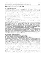
Surface and
Coatings Technology
.
Applied Physics,
J. Micro-Nanolith.
MEMS MOEMS
EUV Sources for Lithography
Surface and Coatings Technology
J. Phys. D
Appl. Phys
Surface and Coatings Technology
Thin Solid Films
Proceedings of the SPIE
Applied
Physics B: Lasers and Optics
IX Int. Conf. on
Plasma Surface Engineering
VEIT 2005, Abstracts,
pag. 77-78
Surface and
Coatings Technology
Intl. Semiconductor Conf. Proceedings,
EUV Source Workshop
Surface and Coatings Technology
Microelectron.
Eng
ń ł
Journal of Alloys and
Compounds
Proceedings of SPIE
J. Appl. Phys
J. Phys. Chem. Ref. Data
J. Phys. Chem. Ref. Data
d
Phys.Rev.B
Handbook of Thin film Process
Technology, F5 – Multilayered structures for X Ray mirrors,
Microelectronic
Engineering
Lithography-Introduction to Microelectronic Fabrication
Phys. Rev. B
International EUVL Symposium
Proceedings of the SPIE ,
Emerging Lithographic Technologies IX
Proceedings of the SPIE
Surface and Coatings Technology
J. Micro-Nanolith. MEMS MOEMS
Journal of Applied Physics
MRS Bull.
Applied Physics Letters
Microelectronic
Engineering
Microelectronic Engineering
J. Phys. D Appl. Phys
IEEE J. Quantum
Electron
Plasma
Sources Sci. Technol
Microelectronic Engineering
Plasma Process. Polym
Journal of Nanoscience
and Nanotechnology
Nuclear Instruments and Methods in Physics Research Section
A: Accelerators, Spectrometers, Detectors and Associated Equipment
X-ray Lasers
Scripta Materialia
Vacuum
11
Steady-state and Time-dependent
LPP Modeling
White, Dunne, and O’Sullivan
University College Dublin
Ireland
1. Introduction
A primary goal in developing extreme ultraviolet lithography (EUVL) is the modeling of
plasma-based light sources, created either by intense lasers or high-current pulsed
discharges, which have applications in semiconductor lithography, nanotechnology, and
plasma diagnostics (Attwood, 2004, Derra et al., 2005). Such modeling can be the key factor
to important scientific and technological solutions in EUVL source optimization. Radiation
hydrodynamic modeling is also important in astrophysics and inertial confinement fusion.
As stated in the International Technology Roadmap for Semiconductors (2008), “Extreme
ultraviolet lithography is expected to provide a single exposure solution for use in
manufacturing starting at 22 nm half pitch and possibly for 32 nm half pitch.“ To match the
proposed multilayer Mo/Si mirror imaging system (~70% refelctivity at 13.5 nm), the EUVL
wavelength of choice for high-density, low-cost integrated circuits is 13.5 nm, created either
by a tin containing laser-produced plasma (LPP) or discharge produced plasma (DPP). The
source power must be greater than 180 W at intermediate focus.
In-band EUV emission (13.365–13.635 nm) in a range of overlapping tin ions (Sn
4+
to Sn
13+
)
has previously been identified as originating from 4d-4f, 4p-4d, and 4d-5p transitions
(O’Sullivan & Carroll, 1981). The source conditions for optimum brightness are in the
computationally challenging non-local thermodynamic equilibrium (non-LTE) (a.k.a.
collisional-radiative or CR) regime, and the emission is highly anisotropic in spectral shape
and intensity (Hayden et al., 2006) for all DPPs and most LPPs (i.e., slab or liquid jet targets).
Xenon and lithium sources have been proposed as possible targets, but are no longer
considered viable (Al-Rabban et al., 2005).
There are numerous challenges to develop and integrate efficient and cost-effective high-
flux plasma EUV sources; in particular the improved conversion efficiency (CE) (ratio of 13.5
nm in-band emission to input laser energy) of the proposed source, and the characterization
and mitigation of debris (fast ions, neutrals, and nanoparticles). Of primary importance is to
identify optimum source parameters (laser wavelength, λ, pulse duration, τ, power density,
Φ, and pulse shape) and material composition (e.g., target shape and ion concentration) for
maximum CE, particularly with the use of reliable modeling tools.
Laser-plasma interaction is complex, but the fundamentals are as follows. A laser is incident
on a target, producing an ablation front, an over-dense region up to 10
3
times solid, which
creates a shockwave in the target as well as heating and ionizing the target to produce an
Lithography
202
expanding plasma, a process that continues throughout the pulse duration. Photons are
absorbed by inverse Bremsstrahlung, and re-emitted via recombination, where up to 80% of
the incident energy can be converted to EUV radiation. The plasma expands (typical ion
velocities are up to 10
6
cm/s) but as electron density decreases, less laser energy is absorbed.
The plasma is a self-regulating regime of generation, heating, and expansion over the pulse
duration, where electrons equilibriate on a very small time scale compared to pulse
duration. Opacity effects are important since emitted radiation can be significantly
reabsorbed within the plasma. A wide range of electron densities and temperatures exist,
which require challenging atomic and plasma hydrodynamic models (Greim, 1964, Key &
Hutcheon, 1980, Carroll & Kennedy, 1981, Attwood, 1999, Al-Rabban et al., 2005).
Section 2 presents a background survey of some typical LPP models, citing conditions for
optimum emission where possible. Major issues in modeling steady-state and time-
dependent plasmas are discussed in Section 3. Firstly, a straightforward steady-state model
in the optically thin regime (emitted radiation not reabsorbed) is used, which provides a
simple estimation of optimum electron temperature at maximum in-band emission, from
which important information about the complex atomic physics in LPPs can be determined.
Secondly, a more sophisticated 1D model that includes radiation transport within an
optically thick plasma (emitted radiation reabsorbed) is used, from which the conversion
efficiency using different laser parameters can be calculated. Some 2D results are also
presented which take into account lateral expansion. Section 4 presents current trends and
future challenges in the field of LPP modeling and EUV source optimisation.
2. Modeling background
To give a background to LPP modeling, a number of cases are cited that highlight a variety
of codes, laser parameters (wavelength, pulse duration, power density), target material and
geometry, and dimension, as well as recent results related specifically to EUVL. The choice
is by no means exhaustive, but is intended to give an idea of the different approaches to
optimising LPP parameters. For brevity, nomenclature is used without introduction, but can
be found in Section 3. Note that the following survey is intended as background only and
the reader is directed to the literature for more detail.
Atomic structure codes such as the HFCI (Hartree Fock with Configuration Interaction) code
of Cowan (Cowan, 1981), GRASP (Grant et al., 1980), HULLAC (Bar-Shalom et al., 2001),
and FAC (Gu, 2003), among others, have been used to determine cross sections and
transitions involved in spectral emission. A number of plasma codes exist to model
hydrodynamics, such as the steady-state, 0D, CR code of Colombant & Tonon (1973), the 1D
Lagrangian code MEDUSA (Christiansen et al., 1974) and the 2D codes CASTOR
(Christiansen & Winsor, 1979), LASNEX (Zimmerman & Kruer, 1975) and Z* (Zakharov et
al., 2005), which all use a simplified single electron model that excludes detailed atomic term
structure. These codes are discussed more fully as applicable below.
The postprocessor FLY code (Lee, 1995) is a time-dependent, single-cell, hydro-dynamics,
CR-based model that solves the differential rate equation using a 1st-order escape
probability approximation, valid for photons that are absorbed locally or escape without
interactions. SWARM (Sondhauss et al., 2001) is a multi-cell extension to FLY using the
Average Atom (AA) model which accounts for non-local re-absorption in the plasma.
Angle-resolved spectra can be calculated for planar, cylindrical, or spherical target
geometries that account for Doppler-shifted anisotropic radiation. FLYCHK is an online
Steady-state and Time-dependent LPP Modeling
203
extension to FLY which incorporates HULLAC atomic data for non-H-, He-, and Li-like
plasmas (Chung et al., 2005). However, accuracy is limited as the AA model is essentially a
Bohr atom approach and ion level energies are assumed to be l-degenerate, a major
drawback when dealing with medium to high Z species such as Sn.
SCROLL (Bar-Shalom, 1997) is a super configuration, non-LTE CR model, which modifies a
simpler LTE model by splitting supershells to populate new superconfigurations
proportional to their partition function (> 10
-5
of total population). Levels up to n = 8 were
considered in optically thin selenium (Z = 34) and lutetium (Z = 71) plasmas.
To account for nl-splitting, the atomic model of Mirone et al. (1997) assumes thermodynamic
equilibrium for population levels using the AA, screened-charge model (a reasonable
assumption where collisions are dominant) to reconstruct the one-electron atomic potentials.
The authors also used the LTE hydrodynamic code MULTI (λ = 0.53-μm, τ = 0.5-ns, 3-μm
diameter germanium target) to highlight the effect of radiation loss in non-LTE conditions.
Their simulations showed that a non-LTE plasma model produces a hotter corona, reduced
radiative heat wave, and more penetration than in an LTE plasma, though less so with their
reconstructed versus hydrogenic model.
The kinematics of supersonic ionization fronts and radiation transport was studied in
Gumbrell et al. (1998) for ps-pulses, where measured plasma velocities are up to 40 times
greater than for ns-pulses. A 1D laser-plasma hydrodynamics code based on MEDUSA was
used to describe heating within the target.
Dürsterer et al. (2001) conducted experiments on oxygen-containing targets (Nd:YAG, 700-
mJ, τ = 8-ns, ~10-μm diameter mass-limited water droplets and 20-μm diameter solid glass
SiO
2
spheres). The authors noted that laser energy absorption is always less than 100% but is
insufficient for pulses of either too short or too long duration: for shorter pulses, absorption
is reduced; for longer pulses, greater expansion reduces electron density below critical
(where the trailing edge of a long pulse is not absorbed at all). They noted a logarithmic
increase in CE over 5 orders of magnitude of pulse duration (200 fs–6 ns), and that energy
was independent of pulse duration for a finite drop for optimum EUV emission because of
the fixed number of atoms. They also noted that a mass-limited droplet expands much faster
and isotropically in 3D compared to an essentially 1D expansion in a bulk target, and
suggested that energy and pulse duration be independently optimized in mass-limited
targets rather than intensity (sufficient for bulk targets). Using a steady-state CR model they
found the optimum electron temperature was 30 eV (reasonably agreeing with a blackbody
model of 95 eV). From MEDUSA simulations, they noted that spherical targets cool faster
and that the position of critical density moves slower than in bulk targets.
Sasaki et al. (2004) use the parametric potential atomic code HULLAC and CR Whiam code
to calculate Xe and Sn emission spectra. The authors assume LTE and a spherical plasma to
simplify the rate equations. For xenon, a calculated spectrum (n
e
= 10
21
cm
-3
at T
e
= 25 eV) is
compared to experiment (Nd:YAG, τ = 8-ns, Φ = 10
12
W/cm
2
, gas jet target), and for tin, a
calculated spectrum (n
e
= 10
20
cm
-3
at T
e
= 22 eV, uniform sphere of radius 30 μm) is
compared to experiment (Φ = 1–9.6 10
11
W/cm
2
). The authors note the effect of satellite lines
in sufficiently dense plasmas (on the long wavelength side of the UTA) and the considerable
opacity effects in a higher density plasma. They also included configuration interaction (CI)
effects to describe the atomic physics in both HULLAC and GRASP. They comment that a
plasma is in quasi-steady-state if the temporal evolution of the EUV spectral intensity is
identical to the input laser pulse shape.
Lithography
204
Fujioka et al. (2005) used a 6-beam, Gekko II laser (λ = 1.053-μm, τ = 5-ns, Φ = 1 x 10
13
W/cm
2
), and observed that the expansion velocity of 3.8 x 10
6
cm/s compared well with that
predicted by ILESTA-1D. The authors noted that the calculated UTA width was broader
than the experimental UTA width (see also Mandelbaum et al. (1997)). Simple modeling
using just gA or f-value distributions for reproducing spectra based on the assumption that
levels are populated uniformly within a particular configuration does not take into account
the energy dependence of the excitation rate coefficients which strongly influence the UTA
shape, however, and accurate term specific rate coefficients are essential for very accurate
modeling. The atomic physics was modelled using HULLAC with CI included, although the
authors noted that disagreements between experimental and calculated spectra result from
the number of configurations used. They noted that opacity effects are a function of plasma
size, and that there are two well-known ways to change plasma size: 1) by incident
wavelength—a shorter wavelength heats higher density regions producing a larger plasma,
2) by pulse duration—a longer duration produces a larger plasma. They also noted that
satellite emission originated from deeper (higher density) layers than the UTA emission.
The experimental CE versus power density was shown to be qualitatively consistent with
their calculated CE (using the 1D code STAR and HULLAC), and that a shorter pulse
duration leads to a higher CE.
Tao et al. (2005) conducted a comparison between experiment (λ = 1.064-μm, τ =10-ns, 220-
μm focal spot diameter, Φ = 0.1-3 x 10
11
W/cm
2
at normal incidence) and a 1D simulation (Φ
= 1 x 10
11
W/cm
2
), which showed reasonable agreement, noting that the difference was
because of lateral expansion not accounted for in the 1D code. The authors noted that
because of a finite focal spot size, which was comparable to the plasma size, lateral
expansion occurs, which removes plasma energy, reduces ion velocity, and reduces ion
density. They commented that due to opacity effects, most of the EUV radiation comes from
the under-dense, coronal region, which they observed using two interferometers and two
probe beams (at 266 nm and 532 nm) to profile electron density along the centre of the
plasma. They observed that at Φ = 1 x 10
11
W/cm
2
the electron temperature in the coronal
region is close to optimum value, whereas at higher intensities it is too hot.
Yamaura et al. (2005) used the 12-beam Gekko XII facility (Nd:YAG, λ = 1064-nm and 4ω
266-nm, τ= 6.5-ns and 10-ns, spatial flattop, Φ = 10
10
-10
11
W/cm
2
at normal incidence, tin
target) and large spot sizes (~500 μm) to exclude the effect of energy loss from lateral
expansion. The authors reported an absorption dip at 13.5 nm for the 266-nm wavelength
due to greater opacity in the lower-wavelength, higher-density plasma, which was
reproduced in a 1D code. They also noted an angular dependence of cos
1.3
θ at 266 nm and
cos
0.5
θ at 1064 nm, and reported that the shifted-peak 4ω spectrum (to 13 nm) could be used
with a modified Mo/Si mirror system.
Shimada et al. (2005) used the 12-beam Gekko XII laser (τ =1.2-ns, target diameter varied
from 300-700-μm, Φ = 0.2–1 x 10
11
W/cm
2
, dodecahedral configuration), primarily used in
fusion research, to uniformly irradiate a spherical tin target and thus remove 2D effects to
compare with a 1D code. Using a EUV pinhole camera, they observed that the diameter of
emission expanded to several tens of microns. They noted that at Φ = 1.2 x 10
11
W/cm
2
, the
temporal EUV profile precisely matched the laser profile, whereas at Φ = 9.6 x 10
11
W/cm
2
,
the spectral maximum occurred much later during the delayed recombination phase. A
maximum CE of 3% occurred at Φ = 0.5–1 x 10
11
W/cm
2
.
Steady-state and Time-dependent LPP Modeling
205
MacFarlane et al. (2005) used the 1D Lagrangian code HELIOS-CR and postprocessor
SPECT3D to study LPPs and z-pinches. The material equations of state are based on
SESAME or PROPACEOS tables and frequency-dependent opacities on non-LTE level
populations. Atomic cross sections were calculated using ATBASE and oscillator strengths
from a HFCI model, where in Sn
10+
, for example, ~500 higher n-shell configurations (to n =
9) and 57 doubly excited configurations were included. More than 5 x 10
6
oscillator
strengths and energy levels from Sn I to Sn XX were computed. In planar geometry,
radiation is transmitted along a single ray at an angle θ with incidence, and in spherical
geometry along a multi-ray conical path. The authors compared HELIOS-CR output to data
from the 12-beam Gekko XII (λ = 1.06-μm, τ = 1.2-ns, Φ = 0.9–9 x 10
11
W/cm
2
, 700-μm
diameter CH spheres coated with a 1-μm tin layer), which showed good agreement with tin
UTA evolution. Planar tin foil experiments were also conducted (λ = 1.06-μm & τ = 1-ns, λ =
0.35-μm & τ = 10-ns) giving a maximum CE of 4.5% for the 1.06-μm & 1-ns case. They also
noted that CEs were higher for targets in front of the laser focus because the plasma couples
to a larger effective laser spot size as it expands outward.
Zakarov et al. (2005) used the 2D RMHD Z* to model EUV spectra in a number of scenarios,
the preprocessing code THERMOS to calculate the spectral and plasma transport
coefficients and material and mixtures EOS database, and the postprocessor code RAY
which includes the effect of complex level kinetics. Z* results (λ = 1064-nm, τ = 15-ns, flat
pulse, 30–300-mJ, 40-μm diameter focussed spot on a 30-μm diameter solid Sn or cryogenic
Xe droplet) showed a CE of about 3% for tin and 0.65% for xenon. The authors noted that
the total emission solid angle is less than 4π because of the target shadow, and that the
plasma is in the shape of a conical shell, which consists of hotspots. Further pre-pulse-pulse
simulations (Zakarov et al., 2007) (Nd:YAG: 2.5-mJ & τ = 10-ns pre-pulse; CO
2
: 50-mJ & τ =
15-ns pulse; on 20-μm Sn droplet) at varying delay times (25–125 ns), showed CE as a
function of delay time, CO
2
pulse duration and energy (τ = 20–100 ns, 20–200 mJ), and CO
2
intensity (Φ = 0.03–2 x 10
11
W/cm
2
).
The Laser Plasma Laboratory at the University of Central Florida (Al-Rabban, 2005)
modelled oxygen (liquid water droplets) in spherical geometry using MED103 (λ = 1064-nm,
τ = 10-ns, 80-μm spot size, Φ = 4.5 x 10
11
W/cm
2
), which predicted a maximum electron
temperature of 56 eV. Line emission was modelled using the LTE code Spectra and atomic
data from the astrophysical Opacity Project database (Z = 1 to 26), which produces synthetic
spectra from 1 to 1000 nm. The authors also used the CHIVAS hydrodynamic code and a CR
ionization model to model xenon droplets, where results showed that “important droplet
expansion occurs at the beginning of the laser pulse, which results in a rather inefficient
overall coupling between the laser and the spray.”
Ando et al. (2006) derived a scaling law for absorption, showing that optical depth is a
function of laser wavelength, pulse duration, and power density. The authors calculated
that a 3–7-ns duration pulse produces an optical depth of 1 cm for a λ = 1064-nm, Φ = 1 x
10
11
W/cm
2
laser. Their experiments (Nd:YAG, λ = 1064-nm, τ = 2–9-ns (Pockels cell), τ = 1–
2-ns (SBS pulse compressor), 300–900-μm spot size with 100-nm Sn layer, Φ =0.1–10 x 10
11
W/cm
2
) showed that the EUV emitting region is thinner for shorter pulses, and that emitted
EUV intensity increases as pulse duration decreases (8.5 to 2.3 ns) but decreases beyond that
(to 1.2 ns). A maximum CE of 2.2% at 2.3 ns and Φ = 5.0 x 10
11
W/cm
2
was observed. They
also noted that an absorption dip at 13.5-nm decreases as the pulse duration decreases, and
that the electron temperature was lower for shorter pulses due to lower absorption.
Lithography
206
Rollinger et al. (2008) used the 2D axisymmetric hydrodynamic code POLLUX (which
incorporates the steady-state CR code of Colombant & Tonon) and the atomic code
HULLAC to determine ion level populations and spectra (as well as assess the limits of
LTE). The authors noted that 1D codes such as MED103 misrepresent electron temperature
and that non-LTE calculations lower the plasma temperature for optimum CE by 3 eV. 2D
target simulations (Nd:YAG, τ =1–15-ns, Φ = 0.1–30 x 10
11
W/cm
2
, 40-μm focal spot size, 50-
μm thick planar Sn target) showed that optimum CE occurs for 3–10 x 10
11
W/cm
2
, noting
that power density primarily determines the electron temperature and thus effects CE more
than pulse duration. They noted that a longer pulse duration produces a larger plume,
which reduces CE because of heat transfer from the hotter core. They also noted that
spherical targets produce lower velocities and a reduced though more 2D plume.
A number of recent experimental results have been reported that have not yet been fully
modelled, but are important with regards to current trends and future challenges in
modeling (see also Section 4). Ueno et al. (2008) noted a 4% CE for a CO
2
laser incident on a
tin cavity target (200 μm). Fujioka et al. (2008a) noted that the target size should equal the
laser spot size to suppress OOB radiation and that debris is reduced by using mass-limited
targets. Sequoia et al. (2008) noted dips in the angular distribution of the in-band EUV
emission at 0° and 30°, which they attributed to 2D plasma expansion. They also noted that
lateral and longitudinal expansion are of similar scale for smaller spot sizes but that
expansion is entirely longitudinal for larger spot sizes (more than a few hundred microns)
and suggested that for higher CE, small focal spot sizes are required to match the target size.
Takahashi et al. (2008) compared the kinetic energy and particle emission for CO
2
and
Nd:YAG lasers at the same energy (50 mJ), observing that the CO
2
laser produces higher ion
kinetic energy (~ 4x) but lower particle emission (1/4) than the Nd:YAG. They commented
that the CO
2
laser was not considered in earlier EUVL research because the deposited
energy was considered too small, but noted that the dominant absorption process for
longer-wavelength lasers is Joule heating (∝ λ
2
) and that once the plasma has formed energy
is absorbed in the plasma surface for a CO
2
laser rather than the target surface, in contrast to
the more penetrating Nd:YAG.
Fujioka et al. (2008b) observed the effect of laser spot size and microdroplet diameter in pre-
pulse-pulse experiments (Nd:YAG pre-pulse, τ = 8-ns, Φ = 3 x 10
11
W/cm
2
, 50-μm focal spot
size, CO
2
main pulse, τ = 40-ns, 1 x 10
10
W/cm
2
, 250-μm focal spot diameter, with optimum
delay of 1 μs) and observed a 4% CE (greater than the 2.5% observed from a single CO
2
pulse on a planar Sn target). They noted that the 20-μm minimum-mass droplet was too
small for optimum laser coupling with the Nd:YAG pre-pulse but was sufficiently expanded
prior to the CO
2
main pulse. They noted that in a 1D simulation of a single CO
2
pulse that
about one half of the incident energy is reflected by the Sn plasma surface and that a pre-
pulse forms a low-density, expanded target which enhances absorption. They also noted
that about 1/3 of the emitted EUV radiation reaches IF, and thus 3 times the IF power is
required at source (545 W into 2π).
In summary, therefore, maximum CEs in the range of 3-4% are predicted for Nd:YAG lasers
operating at power densities of ~ 10
11
W/cm
2
with pulse durations of a few ns, while for
CO
2
systems, because of reduced opacities, higher CEs should be obtainable, this time in the
~ 10
10
W/cm
2
range.
Steady-state and Time-dependent LPP Modeling
207
3. Major Issues
In this chapter, the theoretical analysis and computational methods used to design and
create a LPP light source at 13.5 nm are discussed, with emphasis on tin as the source target.
The Hartree-Fock configuration interaction (HFCI) Cowan code (Cowan, 1981), which
calculates transitions between atomic configurations, and the laser parameters and resultant
plasma conditions needed to produce a tuned LPP light source (O’Sullivan & Faulkner,
1995), are investigated. Unresolved transition array (UTA) statistics are calculated to
characterise spectra, which result from hundreds of thousands of unresolved in-band (13.5
nm ±1%) transitions from a range of tin ions (White et al., 2005).
A steady-state model (Colombant & Tonon, 1973) is presented, which characterises the
plasma by electron temperature, electron density, and average charge state (or ion stage
distribution) from input parameters of laser wavelength, pulse duration, and power density.
To quantify in-band emission, a source metric is presented, which convolves the in-band
emission with ion densities and mirror reflectivity.
Time-dependent, spatially resolved plasmas are analysed with a 1D, hydrodynamic, laser-
plasma interaction code MED103 (Christiansen et al., 1974), where level populations are
calculated using an energy functional method (White et al., 2007). A radiation transport
model for optically thick plasmas is presented to determine the conversion efficiency of laser
energy into useable EUV radiation (Eq. 1).
totout
EdAdtdtICE /),(
%.
%.
∫∫∫
+
−
=
1513
1513 0
τ
λλπ
(1)
where I
out
is the emitted spectral output and E
tot
is the input laser energy.
The effect of laser pulse wavelength (Nd:YAG λ = 1.064 μm and CO
2
λ = 10.6 μm)
especially with respect to the opacity of the plasma is calculated using the 1D model and the
anisotropic nature of the plasma using 2D simulations.
3.1 Atomic physics
Bauche & Bauche-Arnoult (1988a) reported that a transition array is “the totality of lines
between the levels of two electronic configurations.” Peyrusse (1999) reported that
broadband line emission features are present in plasma emission for mid- to high-Z
elements and Jin & Richardson (1995) that “high-Z solid targets, for example, those elements
in the vicinity of tin, characteristically emit broadband spectra that come from many excited
levels. These energy levels are so close that the radiation they generate in the EUV range can
be considered a continuum.” Salzmann (1998) noted that as the number of bound electrons
increases, the density of lines increases such that “their spacing is smaller than their width.”
In a tin plasma, hundreds of thousands of 4d-4f, 4p-4d, and 4p-5d transitions, from near-
degenerate 4p
6
4d
N-1
4f
1
+ 4p
5
4d
N+1
, and 4p
6
4d
N-1
5p
1
(N = 9-1) excited energy levels in Sn
5+
–
Sn
13+
ions, overlap to form a UTA in the in-band EUVL region (O’Sullivan & Carroll, 1981).
To aid the computationally prohibitive calculations, UTAs can be treated statistically, using
moments of the weighted oscillator strength (gf) versus wavelength (
λ
) distribution. The
statistical approach is relevant because of the extreme complexity of the UTA features
(Bauche & Bauche-Arnoult, 1992).
The HFCI Cowan code (Cowan, 1981) solves the multi-electron Schrödinger equation using
the Slater-Condon theory of atomic structure. Configuration interaction (CI) effects are
Lithography
208
known to be considerable between 4p
6
4d
N-1
4f and 4d
5
4d
N+1
configurations and must be
included. The gf versus
λ
distribution is shown in Figure 1, from the HFCI Cowan code for
tin ions in the 12.5–14.5-nm (7.4%) range (the full Mo/Si mirror response region).
12.5 13 13.5 14 14.5
0
50
g
Sn V
12.5 13 13.5 14 14.5
0
50
Sn VI
12.5 13 13.5 14 14.5
0
50
gf
Sn VII
12.5 13 13.5 14 14.5
0
50
Sn VIII
12.5 13 13.5 14 14.5
0
50
λ
(nm)
Sn IX
12.5 13 13.5 14 14.5
0
50
Sn X
12.5 13 13.5 14 14.5
0
50
Sn XI
12.5 13 13.5 14 14.5
0
50
gf
Sn XII
12.5 13 13.5 14 14.5
0
50
Sn XIII
12.5 13 13.5 14 14.5
0
50
λ
(nm)
Sn XIV
Fig. 1. Sn V–Sn XIV weighted oscillator strength versus wavelength (12.5–14.5 nm)
The statistical parameters used to describe a UTA are the weighted mean,
μ
1
, variance, v,
skewness,
α
3
, and kurtosis,
α
4
, determined from the nth-order centred moments of the
distribution (moments about the mean),
μ
n
c
(Bauche & Bauche-Arnoult, 1992). Eq. 2 gives
the nth-order, non-centred moments, expressed by Q
i
, the energy difference between two
levels, and w
i
, the strength of line i (Eq. 3).
∑
∑
=
=
=
N
i
i
i
N
i
n
i
n
w
wQ
1
1
)(
μ
(2)
2
1 '')(
|D| JJw
i
αα
=
(3)
where
D
(1)
is the electric dipole operator and
α
J and
α
'
J
'
are the upper and lower levels.
Steady-state and Time-dependent LPP Modeling
209
The non-centred moments can be expressed in terms of the energy E
i
(or wavelength,
λ
i
) and
weighted oscillator strength, gf
i
, for each line i (Svendsen & O’Sullivan, 1994) (Eq. 4). The gf
values are used instead of intensities, assuming that the populations in the upper level are
proportional to the statistical weight 2J + 1 (Bauche & Bauche-Arnoult, 1988b). The non-
centred moments are centred, from which the UTA statistics are calculated.
∑
∑
=
=
=
N
i
i
i
N
i
n
i
n
gf
gf
1
1
)(
λ
μ
(4)
Skewness is positive (
α
3
> 0) when the distribution is biased towards the right tail (lower
energy or longer wavelength, in this case) and negative towards the left tail (higher energy
or shorter wavelength). Kurtosis compares the distribution to a Gaussian (or normal)
distribution, where
α
4
= 3 for a perfect Gaussian. The full width at half maximum (FWHM)
instead of the variance can also be used as a measure of width (Eq. 5) as can the standard
deviation, σ, the square root of the variance.
σσ
352222 .)log( ==Γ=FWHM
(5)
A UTA can thus be represented as a Gaussian by spectral position and width, in terms of the
mean (
μ
1
) and standard deviation (
σ
) (Eq. 6), and convolved with an area Gaussian equal to
the Σgf to produce a plot of relative intensity versus wavelength for a given ion stage. The
UTA statistics from a full HFCI calculation can be calculated for each transition type based
on the leading eigenvalue percentages (White et al., 2005).
2
2
1
2
2
1
σ
μ
πσ
)(
)(
−
−
=
x
exf
(6)
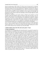
Statistical data from the Cowan code for the 4d-4f, 4p-4d, and 4d-5p transitions are given in
Table 1 and the corresponding Gaussian representation in Figure 2, showing how the
Gaussian representation can be used to greatly simplify complex UTA data.
Figure 3 shows the mean wavelength versus ion stage (error bars as standard deviation) for
the 4d-4f, 4p-4d and 4d-5p transitions, where it is seen that the mean wavelength decreases
with ionisation because of increased Coulombic force, as is to be expected. Note that Δn = 0
transitions are less sensitive than Δn = 1 transitions to the change in average nuclear charge
and that the 4d-5p transition array overlaps with the 4d-4f and 4p-4d UTA in the 13.5-nm
region at Sn XIII.
3.2 Steady-state ion distribution
Transition array statistics simplify numerical calculations involving hundreds of thousands
of spectral lines to help interpret unresolved LPP EUV spectra. The results can be coupled
with a steady-state, CR plasma model (1 electron temperature, 1 electron density)
(Colombant & Tonon, 1973) to quantify in-band emission in an optically thin plasma or with
a time-dependent hydrodynamic model to calculate CE for an optically thick plasma.
Lithography
210
Ion
#
lines
Σgf
mean
λ
std skew kurt
(nm) (nm)
Sn V 3 2.63 22.61 0.21 5.54 32.55
Sn VI 81 30.43 19.49 0.47 1.92 7.11
Sn VII 721 185.54 17.40 0.61 2.22 8.22
Sn VIII 2825 614.63 15.77 0.62 3.01 15.22
Sn IX 5470 1032.42 14.84 0.64 4.32 26.44
Sn X 5346 1227.41 14.34 0.70 4.17 20.50
Sn XI 2825 940.50 13.87 0.46 4.81 29.68
Sn XII 721 483.43 13.50 0.32 6.21 62.43
Sn XIII 81 129.50 13.36 0.29 8.54 93.94
Sn XIV 3 13.03 13.41 0.22 10.68 115.16
Table 1a. 4d-4f UTA statistics
Ion
#
lines
Σgf
mean
λ
std skew kurt
(nm) (nm)
Sn V 0
Sn VI 3 2.88 15.37 2.28 0.15 1.03
Sn VII 60 75.20 16.36 0.47 -0.06 2.76
Sn VIII 466 362.98 15.05 0.65 2.22 12.26
Sn IX 1718 904.94 14.30 0.59 3.50 27.04
Sn X 3170 1061.48 13.91 0.64 4.62 34.12
Sn XI 3245 888.11 13.64 0.61 4.67 33.33
Sn XII 1718 471.46 13.39 0.59 5.41 38.80
Sn XIII 466 158.26 13.34 0.69 4.61 26.41
Sn XIV 60 53.95 13.29 0.61 5.15 30.24
Table 1b. 4p-4d UTA statistics
Ion
#
lines
Σgf
mean
λ
std skew kurt
(nm) (nm)
Sn V 1 0
Sn VI 60 10.46 30.19 0.72 -0.97 7.72
Sn VII 466 44.24 25.80 0.70 -0.46 5.68
Sn VIII 1718 107.17 22.48 0.63 -0.14 5.14
Sn IX 3245 158.89 19.90 0.53 0.06 5.46
Sn X 3170 129.21 17.80 0.46 0.13 5.90
Sn XI 1718 97.46 16.07 0.41 -0.42 9.02
Sn XII 466 59.19 14.64 0.33 -0.24 6.49
Sn XIII 60 54.73 13.41 0.17 1.36 10.56
Sn XIV 3 1.05 12.43 0.10 -0.27 3.01
Table 1c. 4d-5p UTA statistics
Steady-state and Time-dependent LPP Modeling
211
5 10 15 20 25
0
20
40
60
Wavelength (nm)
gf
Sn VIII
# lines = 38246
range = 5.96-29.27 nm
Σ
gf = 1573.44
μ
1 = 15.01
σ
= 2. 90
α
3 = 0.58
α
4 = 4.57
5 10 15 20 25
0
20
40
60
Wavelength (nm)
gf
Sn IX
# lines = 72089
range = 5.71-27.99 nm
Σ
gf = 2535.42
μ
1 = 14.33
σ
= 2. 30
α
3 = -0. 07
α
4 = 5.16
5 10 15 20 25
0
20
40
60
Wavelength (nm)
gf
Sn X
# lines = 100128
range = 4.87-24.09 nm
Σ
gf = 2759.33
μ
1 = 13.77
σ
= 2. 08
α
3 = -1. 29
α
4 = 6.50
5 10 15 20 25
0
20
40
60
Wavelength (nm)
gf
Sn XI
# lines = 68422
range = 4.61-24.84 nm
Σ
gf = 2152.88
μ
1 = 13.34
σ
= 1. 95
α
3 = -2. 07
α
4 = 8.01
5 10 15 20 25
0
20
40
60
Wavelength (nm)
gf
Sn XII
# lines = 27239
range = 4.17-22.84 nm
Σ
gf = 1132.92
μ
1 = 12.97
σ
= 1. 99
α
3 = -2. 37
α
4 = 8.44
5 10 15 20 25
0
20
40
60
Wavelength (nm)
gf
Sn XIII
# lines = 7521
range = 3.66-22.10 nm
Σ
gf = 390.70
μ
1 = 12.65
σ
= 2. 29
α
3 = -2. 17
α
4 = 7.01
Fig. 2. Calculated discrete Cowan (blue), Gaussian (black), and skewed Gaussian (red) (Sn
VIII–Sn XIII)