Solar Collectors and Panels, Theory and Applicationsband (CTB) Part 16 doc
Bạn đang xem bản rút gọn của tài liệu. Xem và tải ngay bản đầy đủ của tài liệu tại đây (162.96 KB, 4 trang )
Working Fluid Selection for Low Temperature Solar Thermal Power Generation
with Two-stage Collectors and Heat Storage Units
441
Organic fluid Irradiation
2
/Wm
R123 R113 R245fa pentane butane
opt. y % 22.1 23.2 25.6 19.5 23.2
max.
,
f
o
x
0.347 0.326 0.320 0.334 0.309
650
max.
c
η
%
47.37 47.30 48.33 46.45 48.18
opt. y % 18.9 18.8 24.0 17.6 21.7
max.
,
f
o
x
0.494 0.459 0.493 0.473 0.479
750
max.
c
η
%
49.23 49.18 50.12 48.56 50.04
opt. y % 17.9 17.7 21.7 16.4 20.2
max.
,
f
o
x
0.649 0.604 0.672 0.623 0.658
850
max.
c
η
%
50.70 50.56 51.51 50.13 51.41
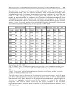
Table 5. Performance analysis of working fluids on the two-stage collectors
On condition of irradiation of 750
2
/Wm, the maximum heat collection efficiency for R123,
R113, R245fa, pentane or butane is about 49.23%, 49.18%, 50.12%, 48.56% or 50.04%
respectively. And the relative increment of heat collection efficiency is 5.94%, 6.80%, 6.60%,
4.73% or 6.45% respectively as compared with that of single-stage collectors (table 4).
6. Conclusion
Heat transfer irreversibility between conduction oil and organic fluids will be large if single-
stage collectors are adopted. The low temperature solar thermal electric generation with
two-stage collectors and heat storage units gives a flexible system which can react to
different operation conditions. Besides, this kind of system displays superior heat collection
efficiency as well as cost-effectiveness.
The regenerator can significantly warm working fluids and complement the heat supplied
from outside. On the condition of evaporation temperature 120°C, environment temperature
20°C and irradiation 750
2
/Wm, the ORC efficiency for R123, R113, R245fa, pentane or
butane is 0.154, 0.161, 0.148, 0.160 or 0.147 respectively. Although R113 and pentane have
the best ORC performance the highest collector efficiency is obtained on the use of R245fa
and butane. And the heat collection efficiency is 49.23%, 49.18%, 50.12%, 48.56% or 50.04%
respectively. The proportion of FPC area to the total collector area plays an important role in
both the overall heat collection efficiency and cost-effectiveness of the two-stage collectors.
And the optimal FPC proportion for R123, R113, R245fa, pentane or butane is 18.9%, 18.8%,
24%, 17.6% or 21.7% respectively. In consideration of frictional resistance of conduction oil
as discussed in Section 4.4, the global electricity would be about 7.49%, 7.83%, 7.31%, 7.68%,
7.25% respectively.
7. Acknowledgments
This study was supported by the National Science Foundation of China [Project Numbers:
50974150, 50978241 and 50708105] and the National High Technology Research and
Development Program of China (863 Program) [Project Number: 2007AA05Z444].
Solar Collectors and Panels, Theory and Applications
442
8. References
[1] Prabhu E. Solar trough ORC. Subcontract report NREL/SR-550-39433 (2006)
[2] Rogers G, Mayhew Y. Engineering thermodynamics, work and heat transfer, 4th ed.
Harlow: Longman Scientific & Technical; (1992)239–243.
[3] Andersen WC, Bruno TJ. Rapid Screening of Fluids for Chemical Stability in Organic
Rankine Cycle Applications. Industrial & Engineering Chemistry Research
44(2005)5560-5566
[4] Sylvain Quoilin, Vincent Lemort. Technological and economical survey of Organic
Rankine Cycle systems, 5
th
European Conference Economics and Management of
Energy in Industry, 14-17 April 2009
[5] Tzu-Chen Huang. Waste heat recovery of organic Rankine cycle using dry fluids. Energy
Conversion & Management 42(2001)539-553.
[6] Bo-Tau Liu, Kuo-Hsiang Chien, Chi-Chuan Wang. Effect of working fluids on organic
Rankine cycle for waste heat recovery. Energy 29(2004)1207-1217.
[7] Bahaa Saleh, Gerald Koglbauer, Martin Wendland, Johann Fischer. Working fluids for
low-temperature organic Rankine cycles. Energy 32(2007)1210-1221.
[8] H.D. Madhawa Hettiarachchi, Mihajlo Golubovic, William M. Worek, Yasuyuki Ikegami.
Optimum design criteria for an Organic Rankine cycle using low-temperature
geothermal heat sources. Energy 32(2007)1698-1706
[9] Drescher and Brueggemann. Fluid selection for the Organic Rankine Cycle (ORC) in
biomass power and heat plants. Applied Thermal Engineering 27 (2007) 223–228
[10] X.D. Wang, L. Zhao, J.L. Wang, W.Z. Zhang, X.Z. Zhao, W. Wu. Performance evaluation
of a low-temperature solar Rankine cycle system utilizing R245fa. Solar Energy 84
(2010) 353–364
[11] S. Canada, G. Cohen, R. Cable, D. Brosseau, H. Price, Parabolic trough organic Rankine
cycle solar power plant, NREL/CP-550-37077, Presented at the 2004 DOE Solar
Energy Technologies, Denver, USA, 2004.
[12] Pei Gang, Li Jing, Ji Jie. Analysis of low temperature solar thermal electric generation
using regenerative Organic Rankine Cycle. Applied Thermal Engineering 2010; 30:
998–1004.
[13] Li jing, Pei gang, Ji jie. Analysis of key factors in low temperature solar thermal electric
power generation with Organic Rankine Cycle. CIESC Journal 60(2009)826-892.
[14] Optimization of low temperature solar thermal electric generation with Organic
Rankine Cycle in different areas. Applied Energy (2010),
doi:10.1016/j.apenergy.2010.05.013
[15] William Stine, Michael Geyer. Power from the sun, Solar Energy Research Institute,
Solar Technical Information Program (U.S.),
[16]
[17] Incropera FP, Dewitt DP, Bergman TL, Lavine AS. Fundamentals of Heat and Mass
Transfer. Ge Xinshi; Ye Hong, trans.6
th
ed. Chemistry Industry Press (Chinese).
2007
[18] Kays W.M, Perkins H.C. Handbook of Heat Transfer. Chapter 7, New York, 1972.
[19] Warren M. Rohsenow, J.P. Hartnett. Handbook of heat transfer, McGraw-Hill, c1973,
14-1
[20]
Working Fluid Selection for Low Temperature Solar Thermal Power Generation
with Two-stage Collectors and Heat Storage Units
443
[21] Ritter Solar product CPC 16w OEM,
[22] NAU FLATLINE BE Ultra,
Nau+GmbH/FLATLINE+BE+Ultra?ep=1&prid=
Nomenclature
A
First heat loss coefficient,
21o
Wm C
−
−
⋅⋅
B
Second heat loss coefficient
22o
Wm C
−−
⋅⋅
p
C
Heat capacity,
11o
Jk
g
C
−
−
⋅⋅
D
Diameter, m
G
Insolation,
2
Wm
−
⋅
h
Enthalpy,
1
Jk
g
−
⋅
m
Mass ratio,
1
k
g
s
−
⋅
Nu
Nusselt number
p
Pressure, Pa
Q
Heat,
1
Jk
g
−
⋅
S
Collector area,
2
m
T
Temperature, ° C
h
Heat transfer coefficient,
21o
Wm C
−
−
⋅⋅
v
Specific volume,
31
mk
g
−
⋅
U
Total heat transfer coefficient,
21o
Wm C
−
−
⋅⋅
W
Power,
1
Jk
g
−
⋅
x
Dryness
Y
Length, m
y
FPC proportion
α
Heat capacity
coefficient,
12o
Jk
g
C
−
−
⋅⋅
ε
Machine efficiency
η
Efficiency
κ
Conductivity,
11o
Wm C
−
−
⋅⋅
υ
Viscosity,
21
ms
−
⋅
Subscripts
1-5 State point
a Environment
c Collector
f Organic fluid
g Generator
h Conduction oil
i Inlet
o Outlet
Solar Collectors and Panels, Theory and Applications
444
p Pump
r Regenerator
t Turbine