Toyota camry hybrid xv50 2012 2017 cooling system làm mát
Bạn đang xem bản rút gọn của tài liệu. Xem và tải ngay bản đầy đủ của tài liệu tại đây (2.55 MB, 33 trang )
2AZ-FXE COOLING – COOLING SYSTEM
CO–1
COOLING SYSTEM
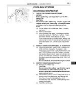
ON-VEHICLE INSPECTION
1.
A135234
INSPECT FOR ENGINE COOLANT LEAK
NOTICE:
Before performing each inspection, turn the A/C
switch OFF.
CAUTION:
Do not remove the radiator cap while the engine and
radiator are still hot. Pressurized, hot engine coolant
and steam may be released and cause serious
burns.
(a) Fill the radiator with coolant and attach a radiator
cap tester.
(b) Set the vehicle to inspection mode. (See page IN-5)
(c) Start the engine, and warm it up.
(d) Using a radiator cap tester, increase the pressure
inside the radiator to 118 kPa (1.2 kgf*cm, 17 psi),
and check that the pressure does not drop.
If the pressure drops, check the hoses, radiator and
water pump for leaks. If no external leaks are found,
check the heater core, cylinder block and cylinder
head.
2.
INSPECT ENGINE COOLANT LEVEL IN RESERVOIR
(a) Check that the engine coolant level is between the
LOW and FULL lines when the engine is cold.
If the engine coolant level is low, check for leaks and
add "TOYOTA Super Long Life Coolant" or similar
high quality ethylene glycol based non-silicate, nonamine, non-nitrite and non-borate coolant with longlife hybrid organic acid technology to the FULL line.
NOTICE:
Do not substitute plain water for engine coolant.
3.
INSPECT ENGINE COOLANT QUALITY
(a) Remove the radiator cap.
CAUTION:
Do not remove the radiator cap while the engine
and radiator are still hot. Pressurized, hot
engine coolant and steam may be released and
cause serious burns.
(b) Check if there are any excessive deposits of rust or
scales around the radiator cap and radiator filler
hole. Also, the coolant should be free of oil.
If excessively dirty, clean the coolant passage and
replace the coolant.
(c) Install the radiator cap.
CO
CO–2
2AZ-FXE COOLING – COOLING FAN SYSTEM
COOLING FAN SYSTEM
2AZ-FXE COOLING
ENGINE
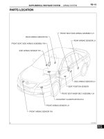
PARTS LOCATION
COOLING FAN MOTOR
CO
ENGINE ROOM RELAY BLOCK
-COOLING FAN RELAY
-CDS FAN FUSE
MAIN BODY ECU (INSTRUMENT PANEL JUNCTION BLOCK)
-ECU IG FUSE NO. 1
-RDI FAN FUSE
A137781E01
CO–3
2AZ-FXE COOLING – COOLING FAN SYSTEM
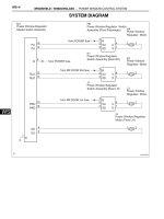
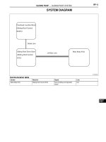
SYSTEM DIAGRAM
A61 Hybrid Vehicle
Control ECU
FAN No. 3
5
2
1
A6 A/C Condenser
Fan Motor
FANL
CDS FAN
5
From Battery
5
2
1
FAN No. 2
4
ECU IG No. 1
From Power
Switch
5
3
1
2
CO
FAN No. 1
1
2
6
FANH
A7 Radiator Fan
Motor
RDI FAN
From Battery
3
5
2
1
A137790
CO–4
2AZ-FXE COOLING – COOLING FAN SYSTEM
ON-VEHICLE INSPECTION
CO
1.
INSPECT COOLING FAN OPERATION AT LOW
TEMPERATURES (Below 83°C (181°F))
(a) Set the vehicle to inspection mode. (See page IN-5)
(b) Start the engine.
(c) Check that the cooling fan stops.
If not, check the cooling fan relay and engine
coolant temperature sensor, and check whether
there is disconnection or an open circuit between
them.
(d) Disconnect the engine coolant temperature sensor
connector.
(e) Check that the cooling fan rotates.
If not, check the fuses, cooling fan relay, ECM and
cooling fan, and check for a short circuit between
the cooing fan relay and engine coolant temperature
sensor.
(f) Reconnect the engine coolant temperature sensor
connector.
2.
INSPECT COOLING FAN OPERATION AT HIGH
TEMPERATURES (Above 93°C (199°F))
(a) Set the vehicle to 2WD inspection mode. (See page
IN-5)
(b) Start the engine, and raise the engine coolant
temperature to above 93°C (199°F).
HINT:
Engine coolant temperature is detected by the
engine coolant temperature sensor on the water
outlet.
(c) Check that the cooling fan rotates.
If not, replace the engine coolant temperature
sensor.
2AZ-FXE COOLING – COOLANT
CO–5
COOLANT
ON-VEHICLE INSPECTION
1.
REMOVE FRONT WHEEL OPENING EXTENSION
PAD RH
2.
REMOVE FRONT WHEEL OPENING EXTENSION
PAD LH
3.
REMOVE ENGINE UNDER COVER LH
4.
REMOVE ENGINE UNDER COVER RH
5.
DRAIN ENGINE COOLANT
NOTICE:
Do not remove the radiator cap sub-assembly while
the engine and radiator are still hot. Pressurized, hot
engine coolant and steam may be released and
cause serious burns.
(a) Remove the radiator cap sub-assembly from the
radiator assembly.
(b) Loosen the radiator drain cock plug and cylinder
block drain cock plug, then drain the coolant.
Radiator Cap
Cylinder Block Drain
Cock Plug
Radiator Drain Cock Plug
A137782E01
HINT:
Collect the coolant in a container and dispose of it
according to the regulations in your area.
6.
ADD ENGINE COOLANT
(a) Close the radiator drain cock plug and 2 cylinder
block drain cock plugs.
Torque: 13 N*m (130 kgf*cm, 9 ft.*lbf) for
cylinder block drain cock plug
CO
CO–6
2AZ-FXE COOLING – COOLANT
(b) Slowly fill the radiator with TOYOTA Super Long Life
Coolant (SLLC).
Specified capacity:
6.2 liters (6.6 US qts, 5.5 lmp. qts)
HINT:
• TOYOTA vehicles are filled with TOYOTA SLLC
at the factory. In order to avoid damage to the
engine cooling system and other technical
problems, only use TOYOTA SLLC or similar
high quality ethylene glycol based non-silicate,
non-amine, non-nitrite, non-borate coolant with
long-life hybrid organic acid technology (coolant
with long-life hybrid organic acid technology
consists of a combination of low phosphates and
organic acids).
• Contact your TOYOTA dealer for further details.
(c) Slowly pour coolant into the radiator reservoir tank
until it reaches the FULL line.
(d) Press the inlet and outlet radiator hoses several
times by hand, and then check the level of the
coolant.
If the coolant level is low, add coolant.
(e) Install the radiator cap sub-assembly and reservoir
tank cap.
(f) Set the vehicle to inspection mode. (See page IN-5)
(g) Start the engine, and warm it up.
HINT:
Adjust the air conditioner set temperature to MAX
(HOT).
(h) Stop the engine, and wait until the engine coolant
cools down.
(i) Add engine coolant to the FULL line on the radiator
reservoir.
CO
7.
INSPECT FOR ENGINE COOLANT LEAK
8.
INSTALL ENGINE UNDER COVER RH
9.
INSTALL ENGINE UNDER COVER LH
10. INSTALL FRONT WHEEL OPENING EXTENSION PAD
LH
11. INSTALL FRONT WHEEL OPENING EXTENSION PAD
RH
2AZ-FXE COOLING – WATER PUMP
CO–7
WATER PUMP
2AZ-FXE COOLING
ENGINE
COMPONENTS
64 (653, 47)
52 (531, 38)
ENGINE MOVING CONTROL
ROD SUB-ASSEMBLY
64 (653, 47)
NO. 2 ENGINE MOUNTING BRACKET RH
NO. 2 ENGINE MOUNTING STAY RH
9.0 (92, 80 in.*lbf)
CO
V-RIBBED BELT TENSIONER
COVER SUB-ASSEMBLY
52 (531, 38)
21 (214, 15)
V-RIBBED BELT
V-RIBBED BELT TENSIONER ASSEMBLY
FRONT FENDER
APRON SEAL RH
ENGINE UNDER
COVER LH
ENGINE UNDER COVER RH
FRONT WHEEL OPENING EXTENSION LH
FRONT WHEEL OPENING
EXTENSION RH
N*m (kgf*cm, ft.*lbf) : Specified torque
A137771E01
CO–8
2AZ-FXE COOLING – WATER PUMP
CLAMP BRACKET
9.0 (92, 80 in.*lbf)
WATER PUMP ASSEMBLY
9.0 (92, 80 in.*lbf)
WATER PUMP PULLEY
CO
26 (265, 19)
26 (265, 19)
9.0 (92, 80 in.*lbf)
N*m (kgf*cm, ft.*lbf) : Specified torque
A137772E01
2AZ-FXE COOLING – WATER PUMP
CO–9
REMOVAL
1.
REMOVE FRONT WHEEL OPENING EXTENSION
PAD RH
2.
REMOVE FRONT WHEEL OPENING EXTENSION
PAD LH
3.
REMOVE ENGINE UNDER COVER RH
4.
REMOVE ENGINE UNDER COVER LH
5.
DRAIN ENGINE COOLANT (See page CO-5)
6.
REMOVE FRONT FENDER APRON SEAL RH
7.
REMOVE NO. 2 ENGINE MOUNTING STAY RH (See
page EM-91)
8.
REMOVE ENGINE MOVING CONTROL ROD SUBASSEMBLY (See page EM-91)
9.
REMOVE NO. 2 ENGINE MOUNTING BRACKET RH
(See page EM-91)
10. REMOVE V-RIBBED BELT TENSIONER COVER SUBASSEMBLY (See page EM-6)
11. REMOVE V-RIBBED BELT (See page EM-6)
12. REMOVE V-RIBBED BELT TENSIONER ASSEMBLY
(See page EM-100)
13. REMOVE WATER PUMP PULLEY
(a) Using SST, remove the 4 bolts and water pump
pulley.
SST 09960-10010 (09962-01000, 09963-00700)
SST
A098715E03
14. REMOVE WATER PUMP ASSEMBLY
(a) Remove the clamp of the crankshaft position sensor
from the water pump.
(b) Disconnect the wire of the crankshaft position
sensor from the clamp bracket.
A094516E01
CO
CO–10
2AZ-FXE COOLING – WATER PUMP
(c) Remove the 4 bolts, 2 nuts and clamp bracket.
Clamp Bracket
B012052E03
(d) Using a screwdriver, pry between the water pump
and cylinder block, and then remove the water
pump.
HINT:
Tape the screwdriver tip before use.
NOTICE:
Be careful not to damage the contact surfaces of
the water pump and cylinder block.
A129792
CO
Air Hole
INSPECTION
Drain Hole
1.
INSPECT WATER PUMP ASSEMBLY
(a) Visually check the drain hole and air hole for coolant
leakage.
If leakage is found, replace the water pump
assembly.
A128603E01
(b) Turn the pulley, and then check that the water pump
bearing moves smoothly without making a "click"
sound.
If it does not move smoothly, replace the water
pump assembly.
A112198
2AZ-FXE COOLING – WATER PUMP
CO–11
INSTALLATION
1.
Seal Diameter
2.2 to 2.5 mm
(0.09 to 0.10 in.)
A
A
INSTALL WATER PUMP ASSEMBLY
(a) Remove any old seal packing material from the
contact surface.
(b) Apply a continuous line of seal packing as shown in
the illustration.
Seal packing:
Toyota Genuine Seal Packing Black, Three
Bond 1207B or equivalent
Standard seal diameter:
2.2 to 2.5 mm (0.09 to 0.10 in.)
NOTICE:
• Remove any oil from the contact surface.
• The parts must be set within 3 minutes after
applying seal packing. Otherwise, the
material must be removed and reapplied.
A-A
0.5 to 1.0 mm
(0.02 to 0.04 in.)
CO
2.5 mm (0.10 in.)
A094495E05
Clamp Bracket
(c) Install the water pump and clamp bracket with the 4
bolts and 2 nuts.
Torque: 9.0 N*m (92 kgf*cm, 80 in.*lbf)
B012052E03
(d) Install the wire of the crankshaft position sensor
onto the clamp bracket.
(e) Install the clamp of the crankshaft position sensor
onto the water pump.
A094516
CO–12
2AZ-FXE COOLING – WATER PUMP
2.
INSTALL WATER PUMP PULLEY
(a) Using SST, install the water pump pulley with the 4
bolts.
SST 09960-10010 (09962-01000, 09963-00700)
Torque: 26 N*m (265 kgf*cm, 19 ft.*lbf)
3.
INSTALL V-RIBBED BELT TENSIONER ASSEMBLY
(See page EM-103)
4.
INSTALL V-RIBBED BELT (See page EM-6)
5.
INSTALL V-RIBBED BELT TENSIONER COVER SUBASSEMBLY (See page EM-7)
6.
INSTALL NO. 2 ENGINE MOUNTING BRACKET RH
(See page EM-30)
7.
INSTALL ENGINE MOVING CONTROL ROD SUBASSEMBLY (See page EM-112)
8.
INSTALL NO. 2 ENGINE MOUNTING STAY RH (See
page EM-112)
9.
CONNECT CABLE TO NEGATIVE BATTERY
TERMINAL (See page EM-113)
SST
A098715E02
CO
10. ADD ENGINE COOLANT (See page CO-5)
11. INSPECT FOR ENGINE COOLANT LEAK (See page
CO-1)
12. INSTALL ENGINE UNDER COVER LH
13. INSTALL ENGINE UNDER COVER RH
14. INSTALL FRONT WHEEL OPENING EXTENSION PAD
RH
15. INSTALL FRONT WHEEL OPENING EXTENSION PAD
LH
CO–12
2AZ-FXE COOLING – THERMOSTAT
THERMOSTAT
2AZ-FXE COOLING
ENGINE
COMPONENTS
THERMOSTAT
9.0 (92, 80 in.*lbf)
GASKET
WATER INLET
CO
RADIATOR HOSE OUTLET
N*m (kgf*cm, ft.*lbf) : Specified torque
Non-reusable part
A137773E01
2AZ-FXE COOLING – THERMOSTAT
CO–13
REMOVAL
1.
REMOVE FRONT WHEEL OPENING EXTENSION
PAD LH
2.
REMOVE FRONT WHEEL OPENING EXTENSION
PAD RH
3.
REMOVE ENGINE UNDER COVER LH
4.
REMOVE ENGINE UNDER COVER RH
5.
DRAIN ENGINE COOLANT (See page CO-5)
6.
DISCONNECT RADIATOR HOSE OUTLET (See page
EM-91)
7.
REMOVE WATER INLET
(a) Remove the 2 nuts and the water inlet from the
cylinder block.
8.
REMOVE THERMOSTAT
(a) Remove the gasket from the thermostat.
CO
A112181
INSPECTION
1.
INSPECT THERMOSTAT
(a) The valve opening temperature is inscribed on the
thermostat.
P013560E01
(b) Immerse the thermostat in water, and then gradually
heat the water.
(c) Check the valve opening temperature of the
thermostat.
Standard valve opening temperature:
80 to 84°C (176 to 183°F)
If the valve opening temperature is not as specified,
replace the thermostat.
P000436E01
CO–14
2AZ-FXE COOLING – THERMOSTAT
Valve Lift
A085445E04
CO
(d) Check the valve lift.
Standard valve lift:
10 mm (0.39 in.) or more at 95°C (203°F)
If the valve lift is not as specified, replace the
thermostat.
(e) Check that the valve is fully closed when the
thermostat is at low temperatures (below 77°C
(171°F)).
If it is not fully closed, replace the thermostat.
2AZ-FXE COOLING – THERMOSTAT
CO–15
INSTALLATION
1.
INSTALL THERMOSTAT
(a) Install a new gasket onto the thermostat.
(b) Install the thermostat with the jiggle valve facing
upward.
HINT:
The jiggle valve may be set to within 10° on either
side of the prescribed position.
Upward
10° 10°
Jiggle Valve
A112199E02
2.
INSTALL WATER INLET
(a) Install the water inlet with the 2 nuts.
Torque: 9.0 N*m (92 kgf*cm, 80 in.*lbf)
3.
CONNECT RADIATOR HOSE OUTLET (See page EM112)
4.
ADD ENGINE COOLANT (See page CO-5)
5.
INSPECT FOR ENGINE COOLANT LEAK (See page
CO-1)
6.
INSTALL ENGINE UNDER COVER LH
7.
INSTALL ENGINE UNDER COVER RH
8.
INSTALL FRONT WHEEL OPENING EXTENSION PAD
LH
9.
INSTALL FRONT WHEEL OPENING EXTENSION PAD
RH
A112181
CO
2AZ-FXE COOLING – COOLING FAN MOTOR
CO–15
COOLING FAN MOTOR
Cooling Fan Motor Side Connector:
ON-VEHICLE INSPECTION
Positive (+)
1.
COOLING FAN MOTOR
(a) Check that the motor turns smoothly when the
battery is connected to the fan motor connector.
(b) Measure the current while the motor is turning.
Standard current:
7.4 to 10.9 A at 20°C (68°F)
If the result is not as specified, replace the cooling
fan motor.
2.
NO. 2 COOLING FAN MOTOR
(a) Check that the motor turns smoothly when the
battery is connected to the fan motor connector.
(b) Measure the current while the motor is turning.
Standard current:
7.4 to 10.9 A at 20°C (68°F)
If the result is not as specified, replace the No. 2
cooling fan motor.
Negative (-)
A103699E02
Cooling Fan Motor Side Connector:
Positive (+)
Negative (-)
A103699E02
CO
CO–16
2AZ-FXE COOLING – COOLING FAN RELAY
1
COOLING FAN RELAY
2
ON-VEHICLE INSPECTION
5
3
1.
5
1
2
3
B060778E01
COOLING FAN RELAY
(a) Remove the relay from the engine room No. 2 relay
block.
(b) Measure the resistance of the relay.
Standard resistance
Tester Connection
Specified Condition
3-5
10 Ω or higher
3-5
Below 1 Ω
(when battery voltage is applied to
terminals 1 and 2)
If the result is not as specified, replace the relay.
(c) Install the relay to the engine room No. 2 relay
block.
2.
1
4
2
4
CO
5
3
1
5
2
3
COOLING FAN RELAY NO. 2
(a) Remove the relay from the engine room No. 2 relay
block.
(b) Measure the resistance of the relay.
Standard resistance
Tester Connection
Specified Condition
3-4
Below 1 Ω
3-5
10 Ω or higher
3-4
10 Ω or higher
(when battery voltage is applied to
terminals 1 and 2)
3-5
Below 1 Ω
(when battery voltage is applied to
terminals 1 and 2)
A087121E01
If the result is not as specified, replace the relay.
(c) Install the relay.
3.
3
5
1
2
1
2
5
3
B060778E45
COOLING FAN RELAY NO. 3
(a) Remove the relay from the engine room No. 2 relay
block.
(b) Measure the resistance of the relay.
Standard resistance
Tester Connection
Specified Condition
3-5
10 Ω or higher
3-5
Below 1 Ω
(when battery voltage is applied to
terminals 1 and 2)
If the result is not as specified, replace the relay.
(c) Install the relay.
2AZ-FXE COOLING – RADIATOR
CO–17
RADIATOR
2AZ-FXE COOLING
ENGINE
COMPONENTS
5.0 (51, 44 in.*lbf)
AIR CLEANER INLET ASSEMBLY
CO
ENGINE UNDER COVER RH
ENGINE UNDER COVER LH
FRONT WHEEL OPENING EXTENSION PAD RH
FRONT WHEEL OPENING
EXTENSION PAD LH
N*m (kgf*cm, ft.*lbf) : Specified torque
A137774E01
CO–18
2AZ-FXE COOLING – RADIATOR
7.0 (71, 62 in.*lbf)
x4
HOOD LOCK ASSEMBLY
RADIATOR SUPPORT UPPER
7.5 (77, 66 in.*lbf)
x2
HORN CONNECTOR
CO
7.0 (71, 62 in.*lbf)
7.5 (77, 66 in.*lbf)
FRONT BUMPER
ENERGY ABSORBER
x2
RADIATOR GRILLE
PROTECTOR
x2
FRONT BUMPER ASSEMBLY
x2
x6
N*m (kgf*cm, ft.*lbf) : Specified torque
A137775E01
CO–19
2AZ-FXE COOLING – RADIATOR
RADIATOR HOSE OUTLET
RADIATOR HOSE INLET
WIRE HARNESS
RADIATOR SUPPORT
CUSHION
RADIATOR ASSEMBLY
FAN ASSEMBLY WITH MOTOR
CO
RADIATOR SUPPORT
LOWER
5.0 (51, 44 in.*lbf)
x4
CONDENSER ASSEMBLY
N*m (kgf*cm, ft.*lbf) : Specified torque
A137780E01
CO–20
2AZ-FXE COOLING – RADIATOR
RADIATOR CAP SUB-ASSEMBLY
RADIATOR TANK UPPER
O-RING
FAN ASSEMBLY WITH MOTOR
CORE SUBASSEMBLY
O-RING
CO
DRAIN PLUG
O-RING
RADIATOR TANK LOWER
Non-reusable part
A137784E01
ON-VEHICLE INSPECTION
1.
1
2
3
4
A107446E01
CHECK RADIATOR CAP SUB-ASSEMBLY
(a) Measure the valve opening pressure.
(1) If there are water stains or foreign matter on
rubber packings 1, 2 or 3, clean the part(s) with
water and finger scouring.
(2) Check that rubber packings 1, 2 and 3 are not
deformed, cracked or swollen.
(3) Check that rubber packings 3 and 4 are not
stuck together.
(4) Apply engine coolant to rubber packings 2 and
3 before using the radiator cap tester.
(5) When using the cap tester, tilt it to 30° or more
above the level.
CO–21
2AZ-FXE COOLING – RADIATOR
(6) Pump the cap tester several times, and check
the maximum pressure *1.
Pumping speed:
1 pump every second
*1: Even if the cap cannot maintain the
maximum pressure, it is not a defect.
Judgment Criteria
Radiator Cap Tester
30° or more
Radiator Cap
A104601E03
Item
Specified Condition
Standard valve
(for brand-new cap)
93.3 to 122.7 kPa (0.95 to 1.25 kgf/
Minimum standard valve
(after using cap)
78.5 kPa (0.8 kgf/cm2, 11.4 psi)
cm2, 13.5 to 17.8 psi)
If the maximum pressure is less than the
specified pressure for the minimum standard
valve, replace the radiator cap sub-assembly.
ON-VEHICLE CLEANING
1.
A073603
INSPECT FINS BLOCKAGE
(a) If the fins are clogged, wash them with water or a
steam cleaner. Dry with compressed air.
NOTICE:
• If the distance between the steam cleaner and
the core is too close, the fins may become
damaged. Keep the following injection
distance.
Standard
Injection Distance
Injection Pressure
300 mm (11.81 in.)
(30 to 50 kg/cm2, 427 to 711 psi)
500 mm (19.69 in.)
2,942 to 4,903 kPa
4,903 to 7,845 kPa
(50 to 80 kg/cm2, 711 to 1,138 psi)
• If the fins are bent, straighten them with a
screwdriver or pliers.
• Never apply water directly onto the electronic
components.
CO
CO–22
2AZ-FXE COOLING – RADIATOR
REMOVAL
1.
DRAIN ENGINE COOLANT (See page CO-5)
2.
REMOVE FRONT WHEEL OPENING EXTENSION
PAD LH
3.
REMOVE FRONT WHEEL OPENING EXTENSION
PAD RH
4.
REMOVE ENGINE UNDER COVER RH
5.
REMOVE ENGINE UNDER COVER LH
6.
REMOVE AIR CLEANER INLET ASSEMBLY (See
page EM-90)
7.
REMOVE FRONT BUMPER ASSEMBLY (See page
ET-3)
8.
REMOVE FRONT BUMPER ENERGY ABSORBER
(See page ET-6)
9.
SEPARATE RADIATOR RESERVOIR TANK HOSE
(a) Separate the radiator reservoir tank hose from the
radiator assembly.
CO
A135233
10. DISCONNECT RADIATOR HOSE INLET
(a) Disconnect the radiator hose inlet from the radiator
assembly.
A137778
11. DISCONNECT RADIATOR HOSE OUTLET
(a) Disconnect the radiator hose outlet from the radiator
assembly.
A137779
2AZ-FXE COOLING – RADIATOR
CO–23
12. SEPARATE WATER HOSE
(a) Separate the 4 clamps and water hose.
A137777
13. REMOVE RADIATOR SUPPORT UPPER
(a) Disconnect the horn connector.
(b) Remove the 3 bolts and separate the hood lock
assembly from the radiator support upper.
A135235
(c) Remove the clamp and separate the hood lock
control cable from the radiator support upper.
A135236
(d) Remove the 5 bolts and radiator support upper.
A137785
14. REMOVE RADIATOR ASSEMBLY
(a) Remove the 4 clamps and 2 connectors.
A137776
CO