Toyota camry hybrid xv50 2012 2017 suspension hệ thống treo
Bạn đang xem bản rút gọn của tài liệu. Xem và tải ngay bản đầy đủ của tài liệu tại đây (5.27 MB, 74 trang )
SUSPENSION – SUSPENSION SYSTEM
SP–1
SUSPENSION SYSTEM
SUSPENSION & AXLE
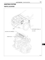
PARTS LOCATION
FRONT SHOCK ABSORBER
FRONT LOWER BALL JOINT
SP
FRONT STABILIZER LINK ASSEMBLY
C143401E01
SP–2
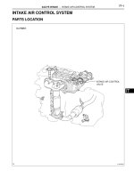
SUSPENSION – SUSPENSION SYSTEM
REAR SHOCK ABSORBER
SP
REAR STABILIZER LINK ASSEMBLY
C143402E01
SP–3
SUSPENSION – SUSPENSION SYSTEM
PROBLEM SYMPTOMS TABLE
Use the table below to help find the cause of the problem.
The numbers indicate the priority of the likely cause of the
problem. Check each part in order. If necessary, replace
these parts
SUSPENSION SYSTEM
Symptom
Bottoming
Sways/pitches
Front wheel shimmy
Rear wheel shimmy
Abnormal tire wear
Suspected Area
See page
1. Vehicle (Overloaded)
-
2. Spring (Weak)
SP-15
3. Shock absorber (Worn)
SP-15
1. Tire (Worn or improperly inflated)
TW-3
2. Stabilizer bar (Bent or broken)
SP-28
3. Shock absorber (Worn)
SP-15
1. Tire (Worn or improperly inflated)
TW-3
2. Wheel (Out of balance)
TW-3
3. Shock absorber (Worn)
SP-15
4. Wheel alignment (Incorrect)
SP-4
5. Lower ball joint (Worn)
SP-23
6. Hub bearing (Worn)
AH-5
7. Steering gear (Out of adjustment or broken)
PS-61
1. Tire (Worn or improperly inflated)
TW-3
2. Wheel (Out of balance)
TW-3
3. Shock absorber (Worn)
SP-35
4. Wheel alignment (Incorrect)
SP-11
5. Hub bearing (Worn)
AH-5
1. Tire (Worn or improperly inflated)
TW-3
2. Wheel alignment (Incorrect)
TW-3
3. Shock absorber (Worn)
SP-15
4. Suspension parts (Worn)
-
SP
SP–4
SUSPENSION – FRONT WHEEL ALIGNMENT
FRONT WHEEL ALIGNMENT
ADJUSTMENT
INSPECT TIRES
(See page TW-3)
2.
MEASURE VEHICLE HEIGHT
(a) Bounce the vehicle up and down at the corners to
stabilize the suspension. Inspect the vehicle height.
Vehicle height
C
D
A
1.
C132408E01
3.
Dimension B
Tread Center
Marks
C125225E02
Rear C - D
56 mm (2.20 in.)
Measuring points:
A:
Ground clearance of front wheel center
B:
Ground clearance of lower suspension arm
No. 2 bushing set bolt center
C:
Ground clearance of rear wheel center
D:
Ground clearance of strut rod set bolt center
NOTICE:
• Before inspecting the wheel alignment, adjust
the vehicle height to the specified value.
• Be sure to perform measurement on a level
surface.
• If it is necessary to go under the vehicle for
measurement, confirm that the parking brake
is applied and the vehicle is secured with
chocks.
B
SP
Front A - B
129 mm (5.08 in.)
INSPECT TOE-IN
(a) Bounce the vehicle up and down at the corners to
stabilize the suspension.
(b) Release the parking brake and move the shift lever
to the neutral position.
(c) Push the vehicle straight ahead approximately 5 m
(16.4 ft). (*1)
(d) Put tread center marks on the rearmost points of the
front wheels and measure the distance between the
marks (dimension B).
(e) Slowly push the vehicle straight ahead to cause the
front wheels to rotate 180° using the front tire valve
as a reference point.
HINT:
Do not allow the wheels to rotate more than 180°. If
the wheels rotate more than 180°, perform the
procedure from *1 again.
SP–5
SUSPENSION – FRONT WHEEL ALIGNMENT
Dimension A
(f)
A
Front
B
Measure the distance between the tread center
marks on the front side of the wheels.
Toe-in
Toe-in
(total)
-
A - B:
0 +- 2 mm (0 +- 0.08 in.)
HINT:
If toe-in is not within the specified range, adjust it at
the rack ends.
C125226E03
4.
C140712
5.
ADJUST TOE-IN
(a) Measure the thread lengths of the right and left rack
ends.
Standard:
Difference in thread length between the right
and left rack ends is 1.5 mm (0.06 in.) or less.
(b) Remove the rack boot set clips.
(c) Loosen the tie rod end lock nuts.
(d) Adjust the rack ends if the difference in thread
length between the right and left rack ends is not
within the specified range.
(1) Extend the shorter rack end if the measured
toe-in deviates toward the outside.
(2) Shorten the longer rack end if the measured
toe-in deviates toward the inside.
(e) Turn the right and left rack ends by equal amounts
to adjust the toe-in.
HINT:
Try to adjust the toe-in to the center of the specified
range.
(f) Make sure that the lengths of the right and left rack
ends are the same.
(g) Tighten the tie rod end lock nuts.
Torque: 74 N*m (755 kgf*cm, 55 ft.*lbf)
NOTICE:
Temporarily tighten the lock nut while holding
the hexagonal part of the steering rack end so
that the lock nut and the steering rack end do
not turn together. Hold the flats on the tie rod
end and tighten the lock nut.
(h) Place the boots on the seats and install the clips.
HINT:
Make sure that the boots are not twisted.
INSPECT WHEEL ANGLE
(a) Put tread center marks on the rearmost points of the
turning radius gauge.
SP
SP–6
SUSPENSION – FRONT WHEEL ALIGNMENT
A
B
B
(b) Turn the steering wheel fully to the left and right and
measure the turning angle.
Wheel turning angle
A
Front
Inside wheel
Outside wheel reference
38°22' +- 2° (38.37° +- 2°)
33°33' (33.55°)
If the right and left inside wheel angles differ from
the specified value, check the right and left rack end
lengths.
A: Inside
B: Outside
C132439E01
6.
Alignment Tester
Gauge
C132440E01
INSPECT CAMBER, CASTER AND STEERING AXIS
INCLINATION
(a) Put the front wheel on the center of the alignment
tester.
(b) Remove the center ornament.
(c) Set the camber-caster-king pin gauge and
attachment at the center of the axle hub or drive
shaft.
(d) Inspect the camber, caster, and steering axis
inclination.
Camber
Camber
Right-left difference
-0°40' +- 45' (-0.67° +- 0.75°)
45' (0.75°) or less
Caster
Caster
Right-left difference
2°55' +- 45' (2.92° +- 0.75°)
45' (0.75°) or less
Steering axis inclination
Steering axis inclination
Right-left difference
12°15' +- 45' (12.25° +- 0.75°)
45' (0.75°) or less
NOTICE:
• Perform the inspection while the vehicle is
unloaded.
• The maximum tolerance of the right and left
difference for the camber and caster is 45'
(0.75°) or less.
(e) Remove the camber-caster-king pin gauge and
attachment.
(f) Install the center ornament.
(g) If the caster and steering axis inclination are not
within the specified range after the camber has
been correctly adjusted, recheck the suspension
parts for damage and/or wear.
SP
7.
ADJUST CAMBER
NOTICE:
Inspect toe-in after the camber has been adjusted.
(a) Remove the front wheel.
SUSPENSION – FRONT WHEEL ALIGNMENT
SP–7
(b) Remove the 2 nuts on the lower side of the front
shock absorber.
NOTICE:
Keep the bolts inserted.
(c) Clean the installation surfaces of the front shock
absorber and the steering knuckle.
(d) Temporarily install the 2 nuts (Step A).
C132409
-
(e) Fully push or pull the front axle hub in the direction
of the required adjustment (Step B).
(f) Tighten the nuts.
Torque: 210 N*m (2,141 kgf*cm, 155 ft.*lbf)
NOTICE:
Keep the bolts from rotating when tightening the
nuts.
(g) Install the front wheel.
Torque: 103 N*m (1,050 kgf*cm, 76 ft.*lbf)
+
C111319E01
1
2
C140710E01
(h) Check the camber.
If the measured value is not within the specification,
calculate the required adjustment amount using the
formula below.
Camber adjustment amount = center of the
specified range center - measured value
Check the combination of installed bolts. Select
appropriate bolts from the table below to adjust the
camber to the specified values.
HINT:
Try to adjust the camber to the center of the
specified values.
Move the axle toward (+) in step (B)
Move the axle toward (-) in step (B)
Refer to table (1) (Move the axle toward
the positive side)
Refer to table (2) (Move the axle toward
the negative side)
SP
SP–8
SUSPENSION – FRONT WHEEL ALIGNMENT
Table (1) (Move the axle toward the positive side)
Installed Bolt
1
90105-17012 90105-17012 90105-17012 90105-17012 90105-17013 90105-17014 90105-17015
2
Adjusting Value
90105-17012 90105-17013 90105-17014 90105-17015 90105-17015 90105-17015 90105-17015
-1°30' to -1°15'
(-1.50° to -1.25°)
G
-1°15' to -1°00'
(-1.25° to -1°)
G
A
G
A
B
G
A
B
C
G
A
B
C
D
G
A
B
C
D
E
F
-1°00' to -0°45'
(-1° to -0.75°)
-0°45' to -0°30'
(-0.75° to -0.5°)
-0°30' to -0°15'
(-0.5° to -0.25°)
-0°15' to 0°
(-0.25° to 0°)
SP
0° to 0°15'
(0° to 0.25°)
A
B
C
D
E
0°15' to 0°30'
(0.25° to 0.5°)
B
C
D
E
F
0°30' to 0°45'
(0.50° to 0.75°)
C
D
E
F
0°45' to 1°00'
(0.75° to 1°)
D
E
F
1°00' to 1°15'
(1° to 1.25°)
E
F
1°15' to 1°30'
(1.25° to 1.5°)
F
Selected Bolt Combination
A
B
C
D
E
F
G
1
90105-17012 90105-17012 90105-17012 90105-17013 90105-17014 90105-17015 90105-17012
2
90105-17013 90105-17014 90105-17015 90105-17015 90105-17015 90105-17015 90105-17012
C138332E01
SP–9
SUSPENSION – FRONT WHEEL ALIGNMENT
Table (2) (Move the axle toward the negative side)
Installed Bolt
1
90105-17012 90105-17012 90105-17012 90105-17012 90105-17013 90105-17014 90105-17015
2
Adjusting Value
90105-17012 90105-17013 90105-17014 90105-17015 90105-17015 90105-17015 90105-17015
-1°30' to -1°15'
(-1.50° to -1.25°)
F
-1°15' to -1°00'
(-1.25° to -1°)
E
F
-1°00' to -0°45'
(-1° to -0.75°)
D
E
F
-0°45' to -0°30'
(-0.75° to -0.5°)
C
D
E
F
-0°30' to -0°15'
(-0.5° to -0.25°)
B
C
D
E
F
-0°15' to 0°
(-0.25° to 0°)
A
B
C
D
E
F
G
A
B
C
D
E
G
A
B
C
D
G
A
B
C
G
A
B
G
A
0° to 0°15'
(0° to 0.25°)
0°15' to 0°30'
(0.25° to 0.5°)
0°30' to 0°45'
(0.50° to 0.75°)
0°45' to 1°00'
(0.75° to 1°)
1°00' to 1°15'
(1° to 1.25°)
1°15' to 1°30'
(1.25° to 1.5°)
SP
G
Selected Bolt Combination
A
B
C
D
E
F
G
1
90105-17012 90105-17012 90105-17012 90105-17013 90105-17014 90105-17015 90105-17012
2
90105-17013 90105-17014 90105-17015 90105-17015 90105-17015 90105-17015 90105-17012
C138332E02
SP–10
SUSPENSION – FRONT WHEEL ALIGNMENT
(i)
SP
The body and suspension may be damaged if the
camber is not correctly adjusted according to the
above table.
NOTICE:
Replace the nut with a new one when replacing
the bolt.
Repeat the steps mentioned above. In step (A),
replace 1 or 2 selected bolts.
HINT:
Replace one bolt at a time when replacing 2 bolts.
SP–16
SUSPENSION – FRONT SHOCK ABSORBER
REASSEMBLY
1.
INSTALL FRONT SHOCK ABSORBER
(a) Install the front spring bumper to the piston rod.
(b) Install the front coil spring lower insulator onto the
front shock absorber.
NOTICE:
Align the 2 protrusions of the front coil spring
lower insulator and the 2 holes in the front
shock absorber.
C132418
(c) Using SST, compress the front coil spring.
SST 09727-30021 (09727-00010, 09727-00021,
09727-00031)
NOTICE:
Do not use an impact wrench.
HINT:
If the front coil spring is compressed at an angle,
using 2 SST will make the work easier.
SST
C104393E01
(d) Install the front coil spring to the front shock
absorber.
NOTICE:
The smaller diameter end of the front coil spring
must face upward.
HINT:
Fit the lower end of the front coil spring into the gap
of the insulator.
SP
C132419
SUSPENSION – FRONT SHOCK ABSORBER
(e) Install the front coil spring upper insulator as shown
in the illustration.
HINT:
Any misalignment between the front shock absorber
lower bracket and the matchmark must be +-5°.
5°
5°
SP–17
Outside
C132420E01
(f)
5°
5°
Outside
Install the front coil spring upper seat with the mark
facing to the outside of the vehicle.
HINT:
Any misalignment between the front shock
absorber lower bracket and the matchmark must be
+-5°.
C132421E01
(g) Install a new front suspension support bearing as
shown in the illustration.
HINT:
If there is foreign matter inside the front suspension
support bearing, replace it with a new one.
F040162
SP
SP–18
SUSPENSION – FRONT SHOCK ABSORBER
(h) Install the front suspension support sub-assembly.
Temporarily tighten a new lock nut.
NOTICE:
Check that the flats on the piston rod and the
flats on the front suspension support subassembly are aligned.
Outside
C132422E01
(i)
Outside
10° +- 5°
C132423E01
SP
Remove the SST slowly in order to release the coil
spring.
NOTICE:
Do not use an impact wrench.
HINT:
Any misalignment between the front shock absorber
lower bracket and the arrows must be +-5°.
SUSPENSION – FRONT SHOCK ABSORBER
SP–19
INSTALLATION
1.
INSTALL FRONT SHOCK ABSORBER WITH COIL
SPRING
(a) Install the front shock absorber with coil spring to
the front axle assembly and insert the 2 bolts from
the front side of the vehicle.
(b) Slowly jack up the vehicle using a wooden block
and install the front shock absorber with coil spring
(upper side) to the vehicle.
Front
Wooden Block
Wooden Block
C132410E01
(c) Install the 3 nuts to the upper side of the front shock
absorber with coil spring.
Torque: 85 N*m (867 kgf*cm, 63 ft.*lbf)
C132415
SP
SP–20
SUSPENSION – FRONT SHOCK ABSORBER
(d) Install the 2 nuts to the lower side of the front shock
absorber with coil spring.
Torque: 210 N*m (2,140 kgf*cm, 155 ft.*lbf)
NOTICE:
When installing the nuts, keep the bolts from
rotating.
C132414
(e) Install the front flexible hose and front speed sensor
wire harness with the bolt.
Torque: 19 N*m (194 kgf*cm, 14 ft.*lbf)
HINT:
If the ball joint turns together with the nut, use a
wrench (19 mm) to hold the stud.
NOTICE:
Do not twist the front speed sensor wire harness
when installing it.
C132413
(f)
Fully tighten the lock nut.
Torque: 70 N*m (714 kgf*cm, 52 ft.*lbf)
C132412
2.
INSTALL FRONT STABILIZER LINK ASSEMBLY
(a) Install the front stabilizer link assembly with the nut.
Torque: 74 N*m (755 kgf*cm, 55 ft.*lbf)
HINT:
If the ball joint turns together with the nut, use a
wrench (19 mm) to hold the stud.
3.
INSTALL FRONT WHEEL
Torque: 103 N*m (1,050 kgf*cm, 76 ft.*lbf)
4.
INSPECT AND ADJUST FRONT WHEEL ALIGNMENT
(See page SP-4)
Wrench
SP
C147096E01
A
DISPOSAL
25 mm (0.98 in.)
1.
B
C137486E01
DISPOSE OF FRONT SHOCK ABSORBER
(a) Fully extend the shock absorber rod.
(b) Using a drill, make a hole in the cylinder between A
and B as shown in the illustration to discharge the
gas inside.
CAUTION:
• Be careful when drilling because shards of
metal may fly about. Always use the proper
safety equipment.
SUSPENSION – FRONT SHOCK ABSORBER
SP–21
• The gas is colorless, odorless and nonpoisonous.
SP
SP–22
SUSPENSION – FRONT SUSPENSION LOWER NO. 1 ARM
INSTALLATION
1.
A
INSTALL FRONT SUSPENSION LOWER NO. 1 ARM
(a) Install the front lower arm bushing stopper.
(b) Install the front suspension lower No. 1 arm to the
front frame assembly with the 3 bolts and the nut,
but do not tighten them yet.
(c) Tighten the 3 bolts in numerical order shown in the
illustration.
Torque: 200 N*m (2,040 kgf*cm, 148 ft.*lbf) (bolt
A)
206 N*m (2,100 kgf*cm, 152 ft.*lbf) (bolt
B)
A
B
C145854E01
C141491
SP
2.
INSTALL ENGINE MOUNTING INSULATOR
(a) Install the engine mounting insulator with the 3 nuts.
Torque: 87 N*m (887 kgf*cm, 64 ft.*lbf)
3.
INSTALL ENGINE ASSEMBLY WITH TRANSAXLE
HINT:
Refer to the instructions for installation of the engine
assembly (See page EM-107).
SP–24
SUSPENSION – FRONT LOWER BALL JOINT
REMOVAL
HINT:
• Use the same procedures for the RH side and the LH side.
• The procedures listed below are for the LH side.
1.
REMOVE FRONT WHEEL
2.
REMOVE FRONT AXLE HUB NUT (See page DS-5)
3.
SEPARATE FRONT SPEED SENSOR (See page DS-5)
4.
SEPARATE FRONT DISC BRAKE CALIPER
ASSEMBLY (See page AH-6)
5.
REMOVE FRONT DISC (See page BR-50)
6.
SEPARATE TIE ROD END SUB-ASSEMBLY (See page
DS-6)
7.
SEPARATE FRONT SUSPENSION LOWER NO. 1
ARM (See page DS-6)
8.
REMOVE FRONT AXLE ASSEMBLY (See page AH-6)
9.
REMOVE FRONT WHEEL NO. 1 BEARING DUST
DEFLECTOR (See page AH-7)
10. REMOVE FRONT AXLE HUB HOLE SNAP RING (See
page AH-7)
11. REMOVE FRONT AXLE HUB (See page AH-7)
12. REMOVE FRONT DISC BRAKE DUST COVER (See
page AH-8)
13. REMOVE FRONT AXLE HUB BEARING (See page
AH-8)
14. REMOVE FRONT LOWER BALL JOINT
(a) Secure the steering knuckle in a vise using
aluminum plates.
(b) Remove the cotter pin and nut.
(c) Using SST, remove the front lower ball joint.
SST 09628-62011
NOTICE:
• Do not damage the dust cover of the ball
joint.
• Do not damage the steering knuckle.
SP
SST
C107301E01
SUSPENSION – FRONT LOWER BALL JOINT
SP–25
INSPECTION
1.
ZX01712
INSPECT FRONT LOWER BALL JOINT
(a) Inspect the turning of the ball joint.
(1) Secure the front lower ball joint assembly in a
vise using aluminum plates.
(2) Install the nut to the front lower ball joint
assembly stud.
(3) Using a torque wrench, turn the nut
continuously at a rate of 3 to 5 seconds per turn
and take the torque reading on the 5th turn.
Torque: Turning torque
1.0 to 3.4 N*m (10 to 35 kgf*cm, 9 to
30 in.*lbf)
HINT:
If the turning torque is not within the specified
range, replace the front lower ball joint
assembly with a new one.
(b) Inspect the dust cover.
(1) Check that the dust cover is not cracked and
that there is no grease on it.
SP
SP–11
SUSPENSION – REAR WHEEL ALIGNMENT
REAR WHEEL ALIGNMENT
ADJUSTMENT
B
A
1.
INSPECT TIRES
(See page TW-3)
2.
MEASURE VEHICLE HEIGHT (See page SP-4)
3.
INSPECT TOE-IN
(a) Bounce the vehicle up and down at the corners to
stabilize the suspension. Inspect the toe-in.
Toe-in
D
Front
C
Toe-in
(total)
-
A + B:
C - D:
0° +- 24' (0° +- 0.4°)
4 +- 2 mm (0.16 +- 0.08 in.)
If the toe-in is not within the specified range, inspect
the suspension parts and replace them if necessary.
C132438E01
4.
ADJUST TOE-IN
(a) Measure the lengths of the right and left rear No. 2
suspension arms.
Difference in the length between the right and
left rear No. 2 suspension arms:
1.5 mm (0.06 in.) or less
If the left-right difference is larger than 1.5 mm (0.06
in.), adjust it by following the procedures below.
C141329
(b) Loosen the lock nuts.
(c) Turn the right and left adjusting tubes by an equal
amount to adjust toe-in.
HINT:
• Try to adjust toe-in to the center of the specified
range.
• One turn of each adjusting tube will adjust toe-in
by approximately 10.8 mm (0.425 in.).
(d) Tighten the lock nuts.
Torque: 56 N*m (571 kgf*cm, 41 ft.*lbf)
C141330
5.
INSPECT CAMBER
Camber
Camber
Right-left difference
-1°20' +- 45' (-1.33° +- 0.75°)
45' (0.75°) or less
HINT:
Camber is not adjustable. If the measurement is not
within the specification range, inspect the suspension
parts for damage and/or wear, and replace them if
necessary.
SP
SP–26
SUSPENSION – FRONT LOWER BALL JOINT
INSTALLATION
1.
INSTALL FRONT LOWER BALL JOINT
(a) Install the front lower ball joint to the steering
knuckle with the nut.
Torque: 123 N*m (1,250 kgf*cm, 91 ft.*lbf)
NOTICE:
Prevent oil from adhering to the screw and
tapered parts.
(b) Install a new cotter pin.
NOTICE:
If the holes for the cotter pin are not aligned,
tighten the nut further up to 60°.
2.
INSTALL FRONT AXLE HUB BEARING (See page AH9)
3.
INSTALL FRONT DISC BRAKE DUST COVER (See
page AH-9)
4.
INSTALL FRONT AXLE HUB (See page AH-9)
5.
INSTALL FRONT AXLE HUB HOLE SNAP RING (See
page AH-9)
6.
INSTALL FRONT WHEEL NO. 1 BEARING DUST
DEFLECTOR (See page AH-10)
7.
INSTALL FRONT AXLE ASSEMBLY (See page AH-10)
8.
INSTALL FRONT SUSPENSION LOWER NO. 1 ARM
(See page DS-18)
9.
CONNECT TIE ROD END SUB-ASSEMBLY (See page
DS-18)
10. INSTALL FRONT DISC (See page BR-51)
11. INSTALL FRONT DISC BRAKE CALIPER ASSEMBLY
(See page AH-10)
12. INSTALL FRONT SPEED SENSOR (See page DS-18)
13. INSTALL FRONT AXLE HUB NUT (See page AH-11)
SP
14. SEPARATE FRONT DISC BRAKE CALIPER
ASSEMBLY (See page AH-11)
15. REMOVE FRONT DISC (See page BR-51)
16. INSPECT FRONT AXLE HUB BEARING LOOSENESS
(See page AH-5)
17. INSPECT FRONT AXLE HUB RUNOUT (See page AH6)
18. INSTALL FRONT DISC (See page BR-51)
19. INSTALL FRONT DISC BRAKE CALIPER ASSEMBLY
(See page AH-11)
20. INSTALL FRONT AXLE HUB NUT (See page AH-11)
21. CHECK ABS SPEED SENSOR SIGNAL
(See page BC-35)
SUSPENSION – FRONT LOWER BALL JOINT
SP–27
22. INSTALL FRONT WHEEL
Torque: 103 N*m (1,050 kgf*cm, 76 ft.*lbf)
23. INSPECT AND ADJUST FRONT WHEEL ALIGNMENT
(See page SP-4)
SP
SP–12
SUSPENSION – FRONT SHOCK ABSORBER
FRONT SHOCK ABSORBER
SUSPENSION & AXLE
COMPONENTS
FRONT SUSPENSION SUPPORT
SUB-ASSEMBLY
85 (867, 63)
70 (714, 52)
FRONT SUSPENSION
SUPPORT BEARING
FRONT STABILIZER
LINK ASSEMBLY
FRONT COIL SPRING
UPPER SEAT
FRONT SHOCK ABSORBER
WITH COIL SPRING
FRONT COIL
SPRING
74 (755, 55)
FRONT SPEED SENSOR
FRONT SPRING
BUMPER
FRONT COIL SPRING
LOWER INSULATOR
210 (2,141, 155)
SP
FRONT COIL SPRING
UPPER INSULATOR
19 (194, 14)
FRONT FLEXIBLE HOSE
FRONT SHOCK
ABSORBER
FRONT AXLE ASSEMBLY
N*m (kgf*cm, ft.*lbf) : Specified torque
Non-reusable part
C132427E01
SUSPENSION – FRONT SHOCK ABSORBER
SP–13
REMOVAL
HINT:
• Use the same procedures for the RH side and the LH side.
• The procedures listed below are for the LH side.
Front
1.
REMOVE FRONT WHEEL
2.
SEPARATE FRONT STABILIZER LINK ASSEMBLY
(a) Support the front No. 1 suspension lower arm with a
jack using a wooden block to avoid damage.
Wooden Block
Wooden Block
C132410E01
Wrench
C147096E01
(b) Remove the nut and separate the front stabilizer link
assembly from the front shock absorber.
HINT:
If the ball joint turns together with the nut, use a
wrench (19 mm) to hold the stud.
SP
SP–14
SUSPENSION – FRONT SHOCK ABSORBER
3.
REMOVE FRONT SHOCK ABSORBER WITH COIL
SPRING
(a) Loosen the lock nut of the front shock absorber with
coil spring.
NOTICE:
• Do not remove the lock nut.
• Only loosen the nut when disassembling the
front shock absorber with coil spring.
C132412
(b) Remove the bolt and disconnect the front flexible
hose and front speed sensor wire harness from the
front shock absorber with coil spring.
NOTICE:
Be sure to remove the front speed sensor from
the front shock absorber with coil spring.
C132413
(c) Remove the 2 nuts on the lower side of the front
shock absorber with coil spring.
NOTICE:
• When removing the nuts, keep the bolts from
rotating.
• Keep the bolts inserted to secure the front
axle assembly.
C132414
(d) Remove the 3 nuts on the upper side of the front
shock absorber with coil spring.
(e) Lower the front axle assembly, and remove the 2
bolts on the lower side of the front shock absorber.
(f) Remove the front shock absorber with coil spring.
NOTICE:
Make sure that the front speed sensor is
disconnected from the front shock absorber
with coil spring.
SP
C132415
DISASSEMBLY
1.
28 mm
(1.1 in.)
C140711E01
FIX FRONT SHOCK ABSORBER WITH COIL SPRING
(a) As shown in the illustration, secure the front shock
absorber with coil spring in a vise using aluminum
plates by clamping onto a double nutted bolt affixed
to the bracket at the bottom of the absorber.