Energy Management Systems 2012 Part 11 doc
Bạn đang xem bản rút gọn của tài liệu. Xem và tải ngay bản đầy đủ của tài liệu tại đây (779.8 KB, 20 trang )
A New Supercapacitor Design Methodology for Light Transportation Systems Saving
187
Fig. 2. Supercapacitor current-mode control diagram block
Fig. 3. Storage voltage-mode control diagram block
The overhead contact line consists of one main wire having a section of 120 mm
2
for each
direction of the vehicles, as depicted in Fig. 4. In Tab. I the main parameters of the test
system are listed. For simplicity, the simulated track in the paper refers to a branch of 1.5 km
with two regular stops and two trains traveling in different direction. The system during
operating conditions may be affected by high pantograph voltage drop consequent to the
train peak powers, this strongly depending on driving cycles and their diplacement, load
dynamic behaviours and network characteristics. The optimal design of storage devices
based upon supercapacitors is deeply investigated in the following at the aim of obtaining
contemporaneously energy saving, energy efficiency, pantograph voltage stabilization and
peak regularization.
Two case studies will be considerd considered: the first one refers to a storage system based
upon supercapacitors (SC) employment, located at the end of line and the second with
supercapacitors installed onboard.
Energy Management
188
Fig. 4. The light transportation system under study
Parameter Unit Quantity
Track Length [km] 1.5
Contact Wire Resistance (Copper
150 mm
2
)
[/km]
0.125
Rail resistance
[/km]
0.016
Substation internal Resistance
[m]
20
Rated Voltage [V] 750
N° Substations - 1
N° Trains - 2
Average Train
acceleration/deceleration
[m/s
2
] 0.7/0.9
Maximum Train Power [kW] 800
Maximum Braking Power [kW] 400
Train Mass [T] 60
Table I. Light Transportation system Parameters
3.2 Electrical network modeling with stationary ESS
The equivalent circuit of the traction system and the energy storage system located on end
of the line are shown in Fig. 5 in which the subscripts odd and even refer respectively to
A New Supercapacitor Design Methodology for Light Transportation Systems Saving
189
the traction system parameters (contact wire resistance, track resistance, train currents
and pantograph voltages) of both the odd and even tracks. In particular contact wire
resistances will vary as a function of trains positions with respect to the feeding
substations. The railway electrical system can be considered, broadly speaking, as a
distribution system.
R
1,even
I
SUB
R
2,odd
I
2,odd
I
2,even
I
1,even
I
1,odd
R
T
I
T,even
R
2,even
I
T,odd
E
SUB
R
1,odd
V
T,odd
I
STO
E
STO
DC-DC
CONVERTER
V
T,even
V
SUP
C
SUP
Supercapacitors
Fig. 5. Equivalent electrical circuit with wayside energy storage system.
In the model, the traction loads are modeled as current sources, I
Ti
, whose values depend on
the powers required by the trains with reference to the track diagram and on the
pantograph voltages through the relation at the at k-th time step:
()
()
()
k
k
Ti
Ti
k
Ti
P
I
V
k=1, 2,…….,K (1)
where K corresponds to the final state.
The discrete mathematical model is expressed in terms of non linear system where the
power trains and the substation voltage, at generic instant (k), are known quantities. The un-
known quantities are represented by the trains voltage, substation current and storage
current and voltage.
() () () ()
()
1, 1,
1, 1,
()
() () () ()
()
2, 2,
2, 2,
,
()
,
()
1,
,
()
,
11 1 1
0 - -
I
I
11 1 1
0
V
1
V
kk k k
k
even even
odd odd
SUB
k
STO
kk k k
k
even even
odd odd
Todd
k
Todd
k
odd
Teven
k
Teven
RR R R
RR R R
P
R
P
()
()
()
,
() () () ()
()
2, 1, 2,
,
() () () ()
1, 2, 1, 2,
E
E
,
V
111
0
V
11 11
0
k 1, 2, , K.
k
SUB
k
STO
k
Todd
kkkk
k
odd odd odd
Teven
kk kk
odd odd odd odd
RRR
RR RR
(2)
4.3 Electrical network modeling with ESS on board
In 2
nd
case, the equivalent circuit of the traction system and the energy storage systems
located on board are shown in Fig.6. The currents absorbed at trains pantograph is sum of
the actual trains current and storage currents.
Energy Management
190
R
1,even
I
SUB
R
2,odd
I
2,odd
I
2,even
I
1,even
I
1,odd
R
T
I
T,even
-I
STO,even
R
2,even
I
T,odd
-I
STO,odd
R
1,odd
V
T,odd
E
End
V
T,even
Fig. 6. Equivalent circuit with energy storage systems on board
The following mathematical model holds:
() () () ()
()
1, 1,
1, 1,
() () ()
()
2,
2, 2,
(),
,
()
,
()
,
()
,
()
,
11 1 1
0 - -
I
0
11 1
0
V
V
kk k k
k
even even
odd odd
SUB
kk k
k
even
odd odd
kTodd
sto odd
k
Todd
k
Teven
k
sto even
k
Teven
RR R R
RR R
P
I
P
I
()
2,
() () () ()
1, 2, 1, 2,
() () () ()
1, 2, 1, 2,
()
()
()
,
()
,
1
1111
0
11 11
0
E
E
V
V
k
even
kkkk
odd odd odd odd
kk kk
odd odd odd odd
k
SUB
k
End
k
Todd
k
Teven
R
RRRR
RR RR
, k 1, 2, , K.for
(3)
where the power trains, the substation voltage, at generic instant (k), are known quantities.
The unknown quantities are represented by the train voltages, storage currents and end line
voltage.
Finally, both systems are completed taking into account the relation between converter and
supercapacitors device. In fact, with respect to the boost converter laws, the quasi stationary
modeling becomes:
2
()
sup,
(1) ()
sup, sup,
sup,
() () () ()
,
sup, sup, , ,
()
sup,
,
0 k 1,2, ,K-1;
4
k 1,2, ,K;
2
with .
k
j
kk
jj
j
kk kk
Cj
j j stoj stoj
k
j
Cj
I
VV t
C
VVREI
I
R
j odd,even
(4)
A New Supercapacitor Design Methodology for Light Transportation Systems Saving
191
In the 1
st
case (stationary), the storage system is the same for both tracks (odd and even);
otherwise in the 2
nd
case the storage systems are different and the terminal voltage on dc
side of power converters E
sto,j
are the same of terminal voltages at trains pantograph V
T,j
.
The above relationship can be easily deduced by the converter power balance. Hence, by
neglecting the fast transients, the electrical systems can be described as a sequence of
stationary states whose input data are the substation voltages and the train powers for each
current position.
4. Optimal design
Some preliminary concepts are briefly summarized in order to better understand the design
optimization procedure based upon the formulation of an isoperimetric problem.
A rational way to face with this kind of problem is to make the recourse to classical calculus
of variations. Substantially, the objective is to search the functions of extrema of a functional,
subject to known side-conditions. In the following, the Euler-Lagrange formalism of the
calculus of variations is adopted (Pierre 1986).
Let us consider the problem of identifying the real curve x*(t) which yields the minimum or
maximum of the functional:
(,,) ,
b
a
t
t
J
f
xxtdt
where t
a
, t
b
, x(t
a
) = c
a
and x(t
b
) = c
b
are assigned. Provided that the real-valued function
(,,)fxxt
is of class C
2
with respect to all of its argument, in short, a necessary condition is
the well-known Euler-Lagrange equation:
() 0,
xx
d
ff
dt
If a constraint equation of the following kind is imposed:
(,,) ,
b
a
t
t
hgxxtdt
where h is a constant and g a known real-valued function, this equation is usually called
isoperimetric condition. The solution x*(t) which yields the minimum or maximum of the
functional, while satisfying the isoperimetric constraint, is the one obtained by assuming
that x*(t) is a first-variational curve resulting in the minimum or maximum of the functional:
1
(,,) (,,) ,
b
a
t
t
Jfxxtgxxtdt
where
is the Lagrange multiplier.
On the other hand, it is quite impossible to obtain analytical closed solutions for very large
and complex systems, especially if the side-conditions are posed in the form of inequalities.
However, after a discretization procedure, the optimization problem can be formulated as a
Energy Management
192
nonlinear programming problem, as performed in (Battistelli et al. 2009) at the aim of
determining the optimal size of supercapacitor storage systems for transportation systems.
In mathematical terms, the constrained optimization problem can be summarized as:
min
,
.
x, u, m
x,u, m 0
x, u, m 0
where
x is the state variables vector, u the control variables vector, m the parameters vector ,
is the objective function to minimize and
,
refer to equality and inequality constraints
respectively.
The optimal sizing of the energy storage device has to be effected guaranteeing
contemporaneously the voltage profile regularization at both train pantographes, the
substation current minimization and the supercapacitor size reduction. In the case of a
single stationary storage device, this can be pursued by selecting the following objective
function
to be minimized:
22
22
1, 2, 3 4sup
0
T
T even ref T odd ref SUB
wV V wV V wI wI dt
(5)
where
w
1
, w
2
, w
3
and w
4
are suitable coefficients which are able to weight the previously
mentioned requirements,
V
ref
being the rated line voltage. In an analogous way, the proper
objective function for on board arrangement can be determined.
The energy storage conservativeness on the whole time cycle can be described by the
following isoperimetric condition:
sup sup
0
0
T
VIdt
(6)
The isoperimetric problem is completed by the equality constraints which have been
described in 4.3 which substantially take into account the electrical network relationships
and the electrical modeling of components.
In (D. Iannuzzi et al., 2011) the authors have provided an analytical solution to this problem
for a simple case study, on the assumption that the input of the design procedure are the
currents rather than the traction powers, this permitting to obtain a closed form to the
optimization problem. In this paper the discretized version of the optimization problem is
arranged, providing in this way a numerical solution. The sequential quadratic
programming method, which belongs to the class of iterative methods, is employed which
solves at each step a quadratic programming problem.
5. Numerical application
In order to verify the validity of the proposed procedure a realistic case with respect to
actual operation, a 1.5 km double track line, 750 V nominal voltage, is investigated. A 120
seconds operation has been foreseen with two regular stops. The trains, equipped with
regenerative braking, depending on the load dynamic behavior, absorb or generate the
corresponding electrical powers. The simulation data are reported in Table I.
A New Supercapacitor Design Methodology for Light Transportation Systems Saving
193
The driving cycle used for simulation is based on the observations of the real route
measurements. It follows the theoretical directives of accelerating up to 75 km/h with an
acceleration of 1 m/s
2
, whenever it is possible. The electrical power required by the
vehicle has been deduced by measurement at the pantograph during the travel on a
typical track. The data have been post-processed and interpolated. The speed and
electrical power cycles are shown in Fig. 7. It is assumed that the two trains are timely
shifted of 20 s. Substation no load voltage is assumed to be constant and equal to V
0
=
750 V. The storage system has been located at the end of the line in the first case and then
they are located on board.
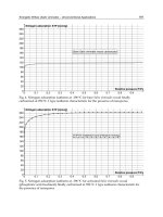
Fig. 7. Traction cycles of the two trains in terms of electrical power at pantograph and
vehicles speed
At this purpose, it has to be highlighted that the traction powers has to be regarded as an
input data in the optimization procedure, the most convenient vehicle displacement being
not investigated.
In order to compare the effectiveness of the storage devices, the reference case, characterized
by the absence of storage device, has been simulated. In Fig.8 the total feeding substation
current, the odd and even pantograph voltages are depicted. In particular during the
acceleration the substation current reaches a peak value of 1.5 kA, the line drop voltage on
both tracks can be observed. The odd voltage at pantograph reaches a minimum value of
600 V with a decreasing of 20% of rated value (750V). On contrary, during the breaking
time the train electrical powers became negative with consequence inversion of the
substation current and increasing of line voltage. In particular the substation current
reaches a negative peak of 500 A and an increasing of line voltage referred to even track
equal to 7% of rated value.
Successively, two cases are examined for which the proposed optimization procedure is
applied. The first one refers to the on-board solution.
The following constraints are imposed:
Energy Management
194
()
()
,
()
,
()
()
sup
0[ ],
600 [ ] 850 [ ],
600 [ ] 850 [ ], 1,2, , .
550 [ ] 900 [ ],
300 [ ] 500 [ ],
k
SUB
k
Todd
k
Teven
k
SUB
k
IA
VV V
VV V k K
VE V
VV V
The optimization procedure is performed, by choosing the following weight coefficients: w
1
,
w
2
. The supercapacitor value has been evaluated by imposing a constraint in terms of
weight. More specifically the weight of the storage device has been constrained to be less
than 2% of the train one.
By following this choice the supercapacitor equivalent capacitance has been resulted equal
to 57 [F] for each train. In the Fig.9 the total feeding substation current, the odd and even
pantograph voltages.
Fig. 8. Substation current and terminal voltages at trains pantograph in the case of absence
of energy storage devices.
In this case the substation current diagram is quite flat and it is unidirectional reaching the
peak value at 600 A, in fact it can be observed a drop voltages at pantograph about the 6-7%
of rated value. This is due to effect of the presence of two supercapacitors devices located on
board. The supercapacitors voltages and the storage currents are reported in Fig.10.
The supercapacitors devices, located on trains odd and even, supply the train during the
acceleration giving a peak currents of about 750 A and 900 A respectively. In fact the
supercapacitors voltages at its terminal decrease up to 300 V during the acceleration. On the
contrary, the electrical energy recovery can be observed during the braking time when the
supercapacitors voltages increase up to their rated values (500 V). So it is quite immediate to
capture the actions of the two storage systems. The energy saving with respect to the base
case is equal to 15,4%.
As far as the second case is concerned, the storage subsystem is placed at the end of a single-
side supplied line.
0 20 40 60 80 100 120
-2000
-1000
0
1000
2000
I
SUB
[A]
0 20 40 60 80 100 120
600
700
800
900
V
T,even
[V]
0 20 40 60 80 100 120
600
700
800
t [s]
V
T,odd
[V]
A New Supercapacitor Design Methodology for Light Transportation Systems Saving
195
Fig. 9. Substation current and terminal voltages at trains pantograph with the energy storage
devices on board.
Fig. 10. Supercapacitors voltages and storage currents for each train
The case corresponding to the weight choice w
1
= w
2
= w
3
= 1 is reported. This choice was
motivated for emphasizing the systemic role played by the storage device which modulates
continuously the electric power, in order to contribute both at voltage profile regularization
and substation current minimization. Also in this case, it can be observed the quite flat
profile of the substation current and the reduced value of the pantographs voltage drop. By
following this choice the supercapacitor equivalent capacitance has been resulted equal to
188 [F]. In the Fig.11 the total feeding substation current, the odd and even pantograph
voltages.
The supercapacitors voltage and the storage current are reported in Fig.12. It can be
observed that in the case of storage device located at the end of line the supercapacitors
current profile is very similar to substation current shown in the fig.8. This shows the
0 20 40 60 80 100 120
0
500
1000
I
SUB
[A]
0 20 40 60 80 100 120
700
750
800
V
T,even
[V]
0 20 40 60 80 100 120
600
700
800
t [s]
V
T,odd
[V]
0 20 40 60 80 100 120
300
400
500
600
t [s]
V
sup,odd
[V]
0 20 40 60 80 100 120
-1000
-500
0
500
1000
I
STO,odd
[A]
t [s]
0 20 40 60 80 100 120
300
400
500
600
V
sup,even
[V]
t [s]
0 20 40 60 80 100 120
-500
0
500
1000
t [s]
I
STO,even
[A]
Energy Management
196
compensation action of supercapacitors during the different operation conditions of the
electrical line.
Fig. 11. Substation current and terminal voltages at trains pantograph in the case of energy
storage devices located at end of line.
Fig. 12. Supercapacitor voltage and storage current
The energy saving with respect to the base case is equal to 11,6%.
6. Conclusion
In the paper a new Supercapacitor Design Methodology for Light Transportation Systems
Saving has been described. The supercapacitor design has been directed towards the energy
efficiency improvement, voltage regulation and high reduction of peak powers requested to
feeding substations during the acceleration and braking phases.
0 20 40 60 80 100 120
0
500
1000
I
SUB
[A]
0 20 40 60 80 100 120
600
700
800
V
T,even
[V]
0 20 40 60 80 100 120
600
700
800
V
T,odd
[V]
t [s]
0 20 40 60 80 100 120
300
400
500
600
t [s]
V
sup
[V]
0 20 40 60 80 100 120
-1000
-500
0
500
1000
I
STO
[A]
t [s]
A New Supercapacitor Design Methodology for Light Transportation Systems Saving
197
More specifically, the supercapacitor design problem for light transportation systems energy
saving has been handled in terms of isoperimetric problem. Starting from this point, the
problem has been tailored as a constrained multiobjective optimization problem which
without restrictions has been proven able to face with all the interest cases. The
optimization procedure has been tested both for both stationary supercapacitors and for on-
board arrangement. The procedure output are the supercapacitor storage size and the
supercapacitor reference voltage which can be employed as reference time trajectory to track
during operating conditions. A numerical application has been performed for a case study
with two trains along double track dc electrified subway networks, both for stationary and
on-board configurations. The obtained numerical results allow to confirm the feasibility and
the goodness of the proposed optimal design technique.
7. References
Chymera, M., Renfrew A. C., Barnes, M., 2006. Energy storage devices in railway systems.
Seminar on innovation in the railways: evolution or revolution?, Austin Court,
Birmingham, UK .
Rufer, A., Hotellier D., Barrade, P., 2004. A Supercapacitor-based energy storage substation for
voltage compensation in weak transportation networks. IEEE Trans. on Power Delivery,
19 (2), pp. 629-636.
Barrero, R., Tackoen, X., Van Mierlo, J., 2008. Improving Energy efficiency in Public Transport:
Stationary supercapacitor based energy storage systems for a metro-network. Proceedings
of Vehicle Power and Propulsion Conf. VPPC’08, Harbin, China, Sept. 2008, pp.1-8.
Hase, S., Konishi, T., Okui, A., Nakamichi, Y., Nara,H., Uemura, T., 2002. Fundamental study
on Energy Storage Systems for dc Electric Railway Systems. Proceedings of Power
Conversion Conf. PCC Osaka 2002 , Osaka, Japan, 2002, pp.1456-1459.
Konishi, T., Hase, S., Nakamichi, Y., 2004-5. Energy Storage System for DC Electrified Railway
Using EDLC. Quarterly Report of RTRI, 45 (2), pp.53-58.
Hase, S., Konishi, T., Okui, A., Nakamichi, Y., Nara,H., Uemura, T., 2003. Application of
Electric Double-layer Capacitors for Energy Storage on Electric Railway. IEEJ Trans. on
Ind. Applicat., 123 (5), pp.517-524.
Iannuzzi, D., 2008. Improvement of the energy recovery of traction electrical drives using
supercapacitors. 13th Int. Power Electronics and Motion Control Conf. EPE-PEMC,
Poznan, Poland, 1-3 Sept., 2008.
Steiner, M., Klohr, M., Pagiela, S.: “Energy Storage System with UltraCaps on Board of Railway
Vehicles”, Proc.of the 12th European Conf. on Power Electronics and Applications,
Aalborg, Denmark , 2-5 Sept., 2007.
Zubieta, L., Bonert, R., 1998. Characterization of double-layer capacitors (DLCs) for power
electronics applications. IEEE Conf. Ind. Appl., St. Louis, MO, USA, 12-15 Oct., 1998,
pp. 1149-1154.
Conway, B. E., 1999. Electrochemical Supercapacitors: Scientific Fundamentals and Technological
Applications. Plenum Publishers Press, New York.
Battistelli, L., Ciccarelli, F., Lauria, D., Proto, D., 2009. Optimal design of DC electrified railway
Stationary Storage Systems. 2nd ICCEP Conference, Capri, Italy, June 9-11, 2009, pp.
739-745.
Luis Zubieta, Richard Bonert, 2000.
Characterization of Double-Layer Capacitors for Power
Electronics Applications ,IEEE Transaction on Ind. Applications, Vol. 36, No. 1
Energy Management
198
Kitahara and A. Watanabe, 1984. Electrical Phenomena at Interfaces: Fundamentals,
measurements and Applications. New York: Marcel Dekker.
R. Morrison, 1990. The Chemical Physics of Surfaces. New York: Plenum.
F. Belhachemi, S. Raiel, and B. Davat, 2000. “A physical based model of power electric double-
layer supercapacitors,” in Proc. Ind. Appl. Conf., vol. 5, pp. 3069–3076.
R. Farande,M. Gallina, and D. T. Son, 2007 “A new simplified model of doublelayer capacitors,” in
Proc. ICCEP, pp. 706–710.
N. Rizoug, P. Bartholomeüs, and P. Le Moigne, 2006. “Modelling of supercapacitors with a
characterization during cycling,” in Proc. PCIM.
R. Kotz and M. Carlen, 2000. “Principles and applications of electrochemical capacitors,”
Electrochim. Acta, vol. 45, no. 15, pp. 2483–2498.
Pierre AD (1986) Optimization theory with applications. Dover Publications, INC., New York.
Iannuzzi D., Lauria D., Tricoli P, Submitted 2011. Optimal Design of Stationary Supercapacitors
Storage Device for Light Electrical Transportation Systems, Engineering Optimization
Journal (Under Review)
10
Management of Locomotive Tractive
Energy Resources
Lionginas Liudvinavičius and Leonas Povilas Lingaitis
Vilnius Gediminas Technical University, Faculty of Transport Engineering
Department of railway transport
Lithuania
1. Introduction
The paper addresses some basic theoretical and engineering problems of electrodynamic
braking, presenting methods of braking force regulation and using of regenerative braking
returning energy (energy saving systems) and diesel engine or any form of hybrid traction
vehicles systems, circuit diagrams, electrical parameters curves. Environmental awareness
plus reduced operating costs are now major considerations in procuring advanced rail
vehicles for considerations in procuring advanced rail vehicles. It is needed to reduce
electric demand, to use new energy savings and power supply optimization, hybrid traction
vehicles systems, which are using regenerative braking energy. Electric braking is effective
on the all speed. Air brake cannot be used. When a vehicle brakes, energy is released to date,
most of this energy is being wasted in air. The challenging alternative is to store the braking
energy on the train and use it during acceleration of operation of the vehicle. Presenting
energy savings power systems, which are using regenerative braking-returning energy and
diesel engine or any form of hybrid traction vehicles systems, light vehicles catenary free
operation, circuit diagrams, electrical parameters curves (Liudvinavičius L. New locomotive
energy management systems, 2010; Sen P. C., Principles of Electric Machines, 1996).
2. New elements-supercapacitors of energy accumulation
Companies of electronics created capacitors of big capacity, which are called in different
countries as ultra condenser, pseudo condenser, supercapacitors, ultracapacitors. In English
literature besides is found the name Electric Double Layer Capacitors. The characteristics of
Fig. 1. High-performance double layer technology capacitor (ultra capacitor) picture
Energy Management Systems
200
supercapacitors are very high. Single module capasities are 3000F, at the tension 2,7V and
even more powerful. (P. Barrade, Series connexion…, 2001). All this has given an impuls to
the various scientific researches. Structure of the supercapacitor is given in Fig.1
Comparative characteristics of the supercapacitors and accumulators are given in the table
below:
Performance Accumulator Supercapacitor
Energy (Wh/kg) 10 – 100 1 – 10
Number of cycles 1000 > 500 000
Specific power (W/kg) < 1000 < 10 000
Table 1. Characteristics of accumulator and supercapacitor.
The charge – discharge time of conventional accumulative batteries is very long, because
chemical reaction depends on time. The charge – discharge time of supercapacitors (J. D.
Boyes…, Technologies for energy…, 2000). is only few seconds. In addition, their period of
duty is incomparably longer. The authors performed first experiments on purpose to
evaluate their technical characteristics in 1997. The diesel engines are used for creating of
primary energy, which power is up to 6000kW. JSC Lithuanian Railways uses diesel engines,
which power is up to 4000 hp. Using conventional systems of starting, from alkaline or acid
accumulators, starting of such engines is very complicated because it requires powerful
batteries of accumulators. During cold season the starting of such power diesel engines is
particularly complicated. If in two or three attempts of starting the diesel engine fails, it is
necessary to change the locomotive in line. If starting of diesel engine is not successful, main
systems of diesel engine freeze, causing considerable material damage. Starting of high-
power diesel engines also is a very complicated in ships. In this case, the consequences even
worse than in the railway. The locomotives TEP-60 and TEP-70, which power of diesel
engines is up to 4000 hp are used for pulling coaches. The locomotives TEP-60 and TEP-70
are with electrical drive. Conventional 110V X 550Ah accumulative batteries, weight of 3400
kg, are used for starting of diesel engines. The experts of Vilnius Gediminas Technical
University and Vilnius locomotive depot have been researching how to extend the life of
battery, reduce their weight, improve the conditions of diesel engine starting up. In Russia
the supercapacitors were bought, for which evaluation of technical abilities the authors
suggested to use them for starting up of the most powerful diesel engine of Lithuanian
Railways, the locomotive TEP-60 with DC/DC current system. The supercapacitor
assembled in a block (in Figure SCB), combining the separate elements sequentially, for the
possibility to connect the capacitor to direct current (DC) of 110V voltage network, and
parallelly, the total capacity must be enlarged (in Farads). For a fast discharge (charge) cycle
of the capacitor, which is calculated by T = RC, the authors suggested to charge the
supercapacitors from conventional charging equipment of accumulators, existing in
locomotive. Fig.2 shows the first (preparatory) phase of diesel engine starting up: the charge
of the supercapacitor (R. G. V. Hermann, High performance…,2001).
Charged supercapacitors to connect parallelly to accumulative battery (conventional battery
of 110V X 550Ah) of much smaller capacity.
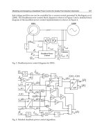
The structure of the locomotive TEP-60 electric drive Traction generator is used to start the
diesel engine, i.e. is running as a conventional starter. In Fig. 3 the diagram is given, where
the generator G, during the starting up is running in mode of direct current (DC) engine.
The scheme of starting up of the diesel locomotive TEP-60 diesel engine is given in Fig.4.
Management of Locomotive Tractive Energy Resources
201
Closing the chain of the contactor K, the starting up of the diesel engine is running, feeding
from accumulative battery (of 110V X 550Ah) of much smaller capacity and parallelly
connected supercapacitors.
Fig. 2. The charge of the supercapacitors from the energy source of locomotive
Fig. 3. The scheme of starting up of the diesel locomotive TEP-60 diesel engine:
DM- diesel engine; G/M- DC electric machine (generator or motor mode G/M) CB-
conventional battery; SCB-block of supercapacitors; L
E
- series existitation winding
3. The results of the research on new energy accumulation elements – using
of the supercapacitors in starting up of diesel engines
In Fig.4 the diagram of locomotive TEP-60 diesel engines’ starter’s running of current
accumulators in chain is given, where the diesel engine is starting up from conventional
batteries (CB), whose parameters are 110V x 110V 550Ah, without SCB and the diagram 2 of
current run, when the diesel engine is started using accumulative batteries of smaller
capacity (110V x 160 Ah) and the block in parallel connected supercapacitors. Using the
Fig. 4. The diagrams of starting up of the TEP-60 diesel engines starter in chain of current
accumulators: 1- baterry current without SCB, when traction generator operates in a starter
mode; 2- baterry current with SCB, when traction generator operates in a starter mode
Energy Management Systems
202
conventional system of current starting up in chain of accumulators is up to 3700A. Using
the conventional system of current starting up in chain of accumulators suggested by the
authors is up to 1200A. The time of Diesel engine starting up, using the conventional system
is 40-50 seconds, and using a complementary system is 7-10 seconds.
4. Locomotive energy saving systems
At this period of time locomotives new energy (3) saving technologies include: 1-optimized
desing vehicle; 2-energy management control system; 3-energy storage system; 4- low
energy climate system; 5-clean diesel motor power pack; 6- new technologies traction motor.
Energy saving up to 8-15% using aeroefficient otimized train, up to 10-15% using energy
management control system, up to 25-30% using energy management control system, up to
25-30% (Liudvinavičius , The aspect of vector , 2009) using energy storage system, up to 25-
30% using low energy climate system. Clean diesel motor power pack reduced particle
emission 70-80%. New technologies traction motor increased energy effiency 2- 4% at
reduced volume and weight. New technogies can create energy savings up to 50%. Fig. 5
shows the possibilities of new energy saving technologies.
Fig. 5. Diagram of locomotive energy saving structure
5. Possibilities of new locomotives regenerative braking
Locomotive electric braking system may be divided into dynamic, and regenerative. Thus,
the dynamic braking energy is converted into heat and dissipated from the system. In other
words, electric energy generated is the typically wasted. In a typical prior art AC
locomotive, however, the dynamic braking grids are connected to the DC traction bus
because each traction motor is normally conected to the bus by the way of autonomous
inverter. Fig. 6 shows that conventional structures electric locomotive AC traction energy
transformed into heat through the braking resistor–R
b
(Liudvinavičius…, Electrodynamic
braking , 2007).
Management of Locomotive Tractive Energy Resources
203
Fig. 6. A circuit diagram of AC/AC conventional electric locomotive dynamic braking:
UCR-uncontrolled rectifier; AI– autonomous inverter; R
b
–braking resistor; M1, M2, M3–one
bogie asynchronous traction motors; WS, ,WS3-wheel-sets
Regenerative braking is more energy effective because power given to catenary power
system is either used by another electric train or returned to power system. Thus, the
conditions for the motor being idle to exceed point
0
n
of torque-speed characteristic
n
f
M , which is required in regenerative braking, cannot be satisfied (see Fig 8).
Locomotive traction motor regenerative braking energy is possiblly returned in to energy
supply system then AC traction motor’s speed is above no -load speed
0
n
. The traction
motor goes to the generator mode, while electromagnetic moment, becomes a braking
moment, and the power produced by generator is given to the catenary (energy power
supply system).
6. Methods of new asynchronous traction motors speed control
The most modern kind of speed control of three-phase induction motors is the control by
changing frequency f
1.
(Lingaitis L.P. , Electric drives , 2006; Strekopytov V , Electric
drives , 2003). It ensures a wide control of range of the speed and causes only little
additional losses.
Relative slip expressed by the formula:
12
1
nn
s
n
; (1)
Where:
1
n – the speed of the rotary field;
2
n –speed of the rotor (rotor speed on load)
f
1
main frequency is:
1
1
60
p
n
f
, f
2
-frequency of the rotor voltage
2
2
60
p
n
f
(there p-is
number of pole pairs). Then:
12
1
ff
s
f
. (2)
Energy Management Systems
204
Asynchronous motor’s rotor speed:
1
21
60
11
f
nn s s
p
; (3)
may be adjusted in the following ways: by adjusting supply voltage
U
1
; by adjusting main
frequency
f
1
; by varying the number of pole pairs-p, speed of the rotor’s rotating field can be
discretely changed; by adjusting slip
s (not using slip energy), the nature of the speed-
torque characteristic can be changed; by adjusting slip
s (using a part of slip energy- cascade
speed control circuits of asynchronous motors). Asynchronous motors with squirrel-cage
rotors and their parameters expressed by the formula:
2
1
111
1
12 1 2
2
r
pmU
s
M
r
f
rxx
s
; (4)
Where
1
p
and
1
m
– are numbers of the stator‘s poles and phases;
1
r
and
1
x
– denote
resistance and inductive impedance of stator;
2
r
and
2
x
– denote resistance and inductive
impedance of rotor reduced in accordance with the stator‘s parameters;
1
U
–is supply
voltage of the stators windings. Optimal mode of operation of asynchronous motors with
squirrel – cage rotors ( Lingaitis L. P. …, Electric drives of traction rolling stocks with AC motors,
2006):
1
11
11 1
f
UM
UfM
. (5)
Hence, an optimal mode of operation of asynchronous motors with squirrel –cage rotors is
defined by the relationship between their three parameters - amplitude of voltage
U
1
,
frequency
f
1
and the developed torque M
1
. A mode of operation of a locomotive can be
described by the locomotive speed V and traction or braking force F
k
of wheel - set. It was
found that:
1
60
0,188 1
μ
f
D
Vs
p
or
1
11
60
0,188
μ
f
D
VC
f
p
, and
2
2
μη
kp
M
FCM
D
(here:
D
– is diameter of the locomotive wheel-set;
is gear ratio;
p
–is gear efficiency)
On the basis of the formula (8), we can determine mode control of locomotives with
asynchronous motors:
11 1
11 1
UVM
UVM
or
11
11
k
k
F
UV
UVF
. (6)
In this case, speed
1
V and traction or braking force
1
F correspond frequency
1
f
, and supply
1
U , or
1
V
and
k
F
traction or braking force in presence of frequency
1
f
and voltage
1
U
When the supply voltage increases, the characteristics move the area of higher speed (Fig 7,
line 2). By changing simultaneously the supply of voltage
U
1
and its frequency f
1
, depending
on mode of regulation, any flat characteristics can be obtained.
Management of Locomotive Tractive Energy Resources
205
Fig. 7. Torque-speed characteristic of induction traction motor’s traction modes by changing
main frequency
f
1
f
i
parameters
Fig. 8. Torque-speed characteristic of induction traction motor’s regenerative braking and
traction modes by changing main frequency
f
1
fi parameters: n
o1
– n
oi
is AC traction
motor’s no
load speed
The frequency controlled squirrel-cage induction motor can be easily showed down by
reducing the supply frequency.
Traction motor’s no-load speed
n
o
is possible by changing the frequency f
1
and to receive
more regenerative braking characteristics and regenerative braking energy returned to
network supply or charging storage battery. Fig. 9 shows AC traction motors new
possibilities of traction and regenerative braking modes operating. The energy management
structure suggested by the authors in Fig.9 will allow the full use of regenerative braking
capabilities: in a high-speed range to return energy for the energy system, in a low-speed
range - to accumulate the energy in a battery of energy accumulating for further use. The
characteristics given in Fig.8 illustrate these findings.
Energy Management Systems
206
Fig. 9. A circuit diagram of AC/AC current system electric locomotive regenerative braking
energy computer control system: M1-M4 – AC traction motors; LD- locomotive driver; A-
analogic – digital converter; T- traction transformer; P- pantograph; VS1-VS10-IGBT
transistors; VD1-VD10-diodes; Y1-four quadrant drive control signals; Y2- inverter drive
control signals;
I
b
-braiking current; Is- stored current; WS1-WS4- wheel-sets
Authors suggested to install storage battery into AC/AC current system conventional
electric locomotive. Fig.9. shows principle of the braking energy management system used
in AC/AC electric locomotive, when a part of regenerative braking energy is returned into
energy supply system and part of energy is stored in storage battery.
7. Hybrid traction propulsion systems
Hybrid traction technology. Energy-saving propulsion system using storage-battery
technology. As the train uses its traction motors the authors suggest to apply a hybrid
propulsion system combining an engine generator with storage batteries (A. Rufer …, A
supercapacitor-based energy storage…
, 2002.). A hybrid energy locomotive system having an
energy storage and regeneration system. The system uses a series-hybrid configuration,
designed to allow immediate system conversion (by replacing conventional diesel-powered
train the engine generator with a fuel-cell unit, in pursuance locomotive modernisation and
ect.). We offer to use a hybrid traction technology. Conventional diesel locomotives powered
with electical transmision can not use regenerative braking energy. Any recovered energy
can be used for traction.
This is expected to give fuel savings of approximately 20%-25% compared with
conventional diesel-powered trains. An engine cutout control is also employed to reduce
noise and fuel consumption while trains are stopping at stations.