Wind Energy Management Part 11 doc
Bạn đang xem bản rút gọn của tài liệu. Xem và tải ngay bản đầy đủ của tài liệu tại đây (1.29 MB, 8 trang )
Modeling and Designing a Deadbeat Power Control for Doubly-Fed Induction Generator
121
link voltage and this one can be controlled by a current control presented by Rodríguez et al.
(2005). The Deadbeat power control block diagram is shown in Figure 3 and a detailed block
diagram of the deadbeat power control implementation is shown in Figure 4.
DIFG
GRID
1
s
Estima
t
or
1
v
1
i
Deadbeat Power
C
ontrol
s
1
ref
P
ref
Q
r
r
v
2
s
1
mec
NP
r
i
2
Fig. 3. Deadbeat power control diagram for DFIG.
ref
Q
)(k
s
dq
)(
1
ki
d
)(
1
ki
q
dq
)(
1
ki
)(
1
ki
)(
2
ki
)(
2
ki
)(
2
ki
d
)(
2
ki
q
)(k
sl
2
R
2
L
M
L
M
Lv
L
1
1
3
2
)(kv
r
2
ref
d
i
2
T
1
)(
2
kv
q
2
R
2
L
1
2
2
L
L
L
M
M
L
ref
P
M
Lv
L
1
1
3
2
ref
q
i
2
T
1
M
L/1
1
1
2
2
L
L
L
M
r
dq
)()( kk
rs
)(kv
r
2
)(
2
kv
d
Fig. 4. Detailed deadbeat power control algorithm.
Wind Energy Management
122
Stator currents and voltages, rotor speed and currents are measured to stator flux position
and magnitude, synchronous frequency and slip frequency estimation.
4.3 Estimation
The stator flux estimation in stationary reference frame αβ is given by
11 111
f
em dt v R i dt
(44)
The position of stator flux is estimated by using the trigonometric function and it is given by
1
1
1
s
tg
(45)
The synchronous speed
ω
1
estimation is given by
1111 1111
1
2
2
11
s
vRi vRi
d
dt
(46)
and the slip speed estimation using the rotor speed and the synchronous speed is
1sl mec
NP
(47)
The angle in rotor reference frame is
sr sl
dt
(48)
5. Experimental results
The deadbeat power control strategy was implemented with a Texas Instruments DSP
TMS320F2812 platform which also has a T = 400µs. The system consists of a three-phase
voltage source inverter with insulated-gate bipolar transistors (IGBTs) and the three-phase
doubly-fed induction generator and its parameters are shown in the appendix. The rotor
voltage commands are modulated by using symmetrical space vector PWM, with switching
frequency equal to 2.5 kHz. The DC bus voltage of the inverter is 36 V. The stator voltages
and currents are sampled in the frequency of 2.5 kHz. The encoder resolution is 3800 pulses
per revolution.
The algorithm of the deadbeat control was programmed on the Event Manager 1 of the
Texas Instruments DSP TMS320F2812 platform and its flowchart is presented in Figure 5.
The schematic of the implementation of the experimental setup is presented in Figure 6 and
the experimental setup is shown in Figure 7.
Six tests were made, five in the subsynchronous operation and one in several speed
operations from supersynchronous to subsynchronous operation. The first one was the
response of
i
2d
step from 0.5A to 5 A which is shown in Figure 8 (a) and the satisfactory
performance of the controller can be seen due to the fact that the reference was followed. In
this test the
i
2q
is 0.5A.
Modeling and Designing a Deadbeat Power Control for Doubly-Fed Induction Generator
123
dt
d
s
1
1111
2
3
ivivQ
1111
2
3
ivivP
dtiRv
1111
1
1
arctan
s
Fig. 5. The flowchart of the DSP program.
Fig. 6. The schematic of the implementation of the deadbeat power control setup.
Wind Energy Management
124
Fig. 7. Experimental Setup.
The second one was the response of
i
2q
step from 0.5A to 5 A. The satisfactory performance
of the controller in this test can be seen in Figure 8 (b), due to the fact that the reference was
followed. In this test
i
2d
is 4A.
The same test of the
i
2q
step from 0A to 5A, as mentioned above, with rotor currents in rotor
reference frame is presented in Figure
9. In this test the i
2d
is 5A. The satisfactory response
of the controller can be seen due to the fact that the reference was followed and the
amplitude of the rotor
ac currents increased.
(a) Response of step test of the
i
2d
. (b) Response of step test of the i
2
q
.
Fig. 8. Response of step test of the rotor current (1.33A/div.).
Modeling and Designing a Deadbeat Power Control for Doubly-Fed Induction Generator
125
The fourth test was the response of the reactive power Q
ref
of -300VA, 300VA and 0VA
which means leg, lead and unitary power factor. The active power reference is -300W. The
rotor current references were calculated using Equations
(41) and (42). The satisfactory
performance of the controller can be seen in Figure 10(a),
due to the fact that the reference
was followed. The rotor current is shown in Figure 10(b).
Fig. 9. Response of step test for i
2q
(1.66 A/div.).
The fifth test was the steady state of unitary power factor and the active power was -300W.
Again, the rotor current references were calculated using Equations
(41) and (42). The
response of stator power and rotor current are presented in Figures 11(a) and 11(b),
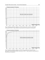
respectively. The stator voltage (127Vrms) and the stator current (0.8Arms) are shown in
Figure 12. The satisfactory performance of the controller can be seen because the angle
between the stator voltage and the stator current is 180°.
(a) Response of step test of the reactive
power (800VA/div.).
(b) Response of step test of the
i
2d
(28A/div.).
Fig. 10. Response of step of reactive power and rotor direct axis current.
Wind Energy Management
126
(a) Response of test of the active and the
reactive power (300VA/div.).
(b) Response of test of the rotor current
(8A/div.).
Fig. 11. Response of steady state test of unitary power factor and the rotor current.
Fig. 12. The stator voltage(18V/div.) and current (0.38A/div.).
In the last test, the generator operates with several speed from 1850 rpm to 1750 rpm and a
constant active and reactive power reference of 0W and 0VA, respectively. The rotor current
references were also calculated using Equations (41) and (42). So, i
2dref
= 7A and i
2qref
= 0A. In
this case, this test just maintains the magnetization of the generator. The response of the
active and reactive power is shown in Figure 13(a) and the rotor current is presented in
Figure 13(b). The rotor speed in several operations and the rotor current of phase α are
shown in Figure 14. The satisfactory performance of the controller can be seen during
several speed operations, since the reference was followed.
Modeling and Designing a Deadbeat Power Control for Doubly-Fed Induction Generator
127
(a) Response of constant active and reactive
power.
(b) Response of constant rotor current.
Fig. 13. Response of the active and reactive power and rotor current.
Fig. 14. Rotor speed and current of phase α (7A/div.).
6. Conclusion
This book chapter has presented a model and design of a deadbeat power control scheme
for a doubly-fed induction generator using a deadbeat control theory and rotor current
space vector loop. The stator field orientation technique allows the independent control of
the rotor current components in synchronous reference frame
dq, in this case, the direct and
quadrature axis of the rotor current space vector. Thus, the control of the rotor current
components allows controlling the active and reactive power of the generator. The deadbeat
controller uses the DFIG discretized equations to calculate at each sample period the
required rotor voltages, so that the active and reactive power values reach the desired
reference values. Thus, the deadbeat controller does not need to tune gains as the PI
controllers. This strategy constant switching frequency overcomes the drawbacks of
conventional direct power control (Xu & Cartwright, 2006).
The experimental results confirm the effectiveness of the power controller during several
operating conditions of generator speed. Thus, the deadbeat power control strategy is an
interesting tool for doubly-fed power control in wind turbines.
Wind Energy Management
128
7. Acknowledgment
The authors would like to thank FAPESP (Fundação de Amparo à Pesquisa do Estado de
São Paulo) for the financial support.
8. Appendix
Doubly-fed induction generator parameters:
R
1
= 2.2 Ω; R
2
= 1.764 Ω; L
m
= 0.0829 H; L
l1
= 0.0074 H; L
l2
=0.0074H ; J = 0.05 Kg.m
2
; NP = 2;
PN = 2.25 kW; VN = 220 V.
9. References
Simões, M. G & Farret, F. (2004). Renewable Energy Systems with Induction Generators. CRC
PRESS.
Jain, A. K. & Ranganathan, R. T. (2008
). Wound Rotor Induction Generator With Sensorless
Control and Integrated Active Filter for Feeding Nonlinear Loads in a Stand-Alone
Grid.
IEEE Transactions on Industrial Electronics, 55 (1), pp. 218-228.
Chowdhury, B. H. & Chellapilla, S. (2006). Double-fed induction generation control for variable
speed wind power generation
. Electric Power System. Research, no. 76, pp. 786–800.
Hopfensperger, B.; Atkinson, D. J.; & Lakin, R. (2000). Stator-flux-oriented control of a
doubly-fed induction machine with and without position encode.
Proc. Inst. Elect.
Eng., Electr. Power Applications
, vol. 147, no. 4, pp. 241–250, April.
Peña, R.; Cárdenas, R.; Proboste, J.; Asher, G.; & Clare, J. (2008). Sensorless control of
doubly-fed induction generators using a rotor-current based MRAS observer
. IEEE
Trans. Ind. Electron
., vol. 55, no. 1, pp.330–339, January.
Morren, J.; Sjoerd, M. & de Haan, W. H. (2005). Ridethrough of wind turbines with doubly-
fed induction generator during a voltage dip.
IEEE Transactions on Energy
Conversion
, vol. 20, no. 2, pp. 435–441, June.
Guo, J.; Cai, X. & Gong, Y. (2008). Decoupled control of active and reactive power for a grid-
connected doubly-fed induction generator.
Third International Conference on Electric
Utility Deregulation and Restructuring and Power Technologies. DRPT 2008
, pp. 2620 –
2625, China, April.
Yao, X.; Jing, Y. & Xing, Z. (2007). Direct torque control of a doubly-fed wind generator
based on grey-fuzzy logic.
International Conference on Mechatronics and Automation.
ICMA 2007
, pp. 3587 – 3592, China, August 2007.
Leonhard
, W. (1985). Control of Electrical Drives. Berlin, Germany: Springer-Verlag.
Novotny, D. W. & Lipo, T. A. (1996
). Vector Control and Dynamics of AC Drives, Clarendon
Press OXFORD.
Franklin, G. F.; Powel, J. D. & Workman, M. L. (1994).
Digital Control of Dynamic Systems.
Addison-Wesley Publishing Company.
Ogata, K. (2002
). Modern Control Engineering. Prentice Hall
Sguarezi Filho, A. J.; de Oliveira Filho, M. E. & Ruppert Filho, E. (2011). A Predictive Power
Control for Wind Energy
. IEEE Transactions on Sustainable Energy, vol. 2, no. 1,
pages: 97-105.
Rodríguez, J. R. & Dixon, J. W.; Espinoza, J. R; Pontt, J.; & Lezana, P. (2005). Pwm regenerative
rectifiers: State of the art
. IEEE Transactions Industrial Electronics, vol. 52, no. 1, February.
Xu, L. & Cartwright, P. (2006). Direct active and reactive power control of DFIG for wind energy
generation.
IEEE Trans. Energy Convers., vol. 21, no. 3, pp. 750–758, September.