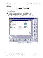
Part Design & Sketcher potx
Bạn đang xem bản rút gọn của tài liệu. Xem và tải ngay bản đầy đủ của tài liệu tại đây (1.07 MB, 30 trang )
Part Design & Sketcher
NATIONAL INSTITUTE FOR AVIATION RESEARCH
Wichita State University
Revision 5.14
Copyright 2005. All rights reserved.
www.cadcamlab.org
None of this material may be reproduced, used or disclosed, in part or in whole, without the expressed written permission of:
National Institute for Aviation Research
Wichita State University
Wichita, KS
Copyright 2005. All rights reserved.
www.cadcamlab.org
CATIA Part Design & Sketcher CATIA® V5R14
Table of Contents, Page i
© Wichita State University
TABLE OF CONTENTS
Introduction 1
ManualFormat 2
PartDesign&Sketcher 3
Log on/off procedures for Windows 4
Tologon 4
Tologoff 5
CATIAVersion5Screen 7
PartDesignScreen 8
Pull-downMenus 9
Start 9
File 10
Edit 11
View 13
Insert 17
Tools 19
Window 24
Help 25
BottomToolbarinPartDesign 26
PartDesignWorkbench 28
SketcherScreen 30
Sketcherchanges 31
BottomToolbar 31
Sketchtools 32
SketcherWorkbench 33
WorkingwithDocuments 35
Typesofdocuments 35
Creatinganewdocument 35
Openinganexistingdocument 36
Savingadocument 37
Closingadocument 38
ManipulatingtheDisplay 39
Threebuttonmouse 39
Twobuttonmouse 39
SpaceBall or SpaceMouse 39
Keyboard 40
KeyboardShortcuts 41
CATIA Part Design & Sketcher CATIA® V5R14
Table of Contents, Page ii
©Wichita State University
BasicSketcher 43
BasicShapes 43
Creatinganewpartwithanewsketch 44
Savingandclosingthepart 45
Rectangle 46
OrientedRectangle 47
Parallelogram 48
ElongatedHole 49
CylindricalElongatedHole 50
Keyhole 52
Hexagon 53
CenteredRectangle 54
CenteredParallelogram 55
Circle 56
Circlethrough3points 57
CirclewithCartesiancoordinates 58
Circletangentto3elements 59
Arcthrough3points 60
Arc through 3 points with limits 61
Arc 62
Spline 63
ConnectCurve 65
Ellipse 67
Parabola 68
Hyperbola 69
Conic 70
Line 75
InfiniteLine 76
Bi-tangentLine 77
BisectLine 79
NormalLinetoCurve 80
Axisline 81
Pointbyclicking 82
Pointbyusingcoordinates 83
Equidistantpoints 84
IntersectionPoint 86
ProjectionPoint 87
Profiles 89
Constraints 106
DimensionalConstraints 106
GeometricalConstraints 106
Operationsonprofiles 153
Corner 153
Chamfer 158
TrimandBreak 162
SpecificationTree 167
Hide/Show 169
CATIA Part Design & Sketcher CATIA® V5R14
Table of Contents, Page iii
© Wichita State University
BasicPartDesign 173
BasicShapes 173
Pad 174
Pocket 184
Multiple Profiles 188
Multi-Pad and Multi-Pocket 190
Shaft 193
Groove 197
Hole 201
Rib 214
Slot 217
Combine 219
Stiffener 221
OperationsonShapes 224
Fillet 224
Chamfer 242
DraftAngle 244
Shell 248
Thickness 250
Thread/Tap 252
Removeface 254
Replaceface 256
Modifyingvalues 258
InterfacingwithSketcher 263
AdvancedSketcher 269
3-DElementsonSketchPlane 269
ConstructionGeometry 275
AdvancedConstraints 277
SketchTransformations 287
SketchAnalysis 297
SketchVisualization 300
AdvancedPartDesign 303
PartTransformations 303
Patterns 309
ModifyingParts 320
InsertingBodiesandBooleanOperations 334
InsertingPartBodies 334
Booleanoperations 335
Part Design Multi-Sections Solids 341
Part Design Using Surfaces 343
Annotations 348
ApplyingMaterials 351
DeleteUselessElements 355
CATIA Part Design & Sketcher CATIA® V5R14
Table of Contents, Page iv
©Wichita State University
Problems 357
Problem #1.0 357
Problem #2.0 358
Problem #3.0 359
Problem #4.0 360
Problem #5.0 361
Problem #6.0 362
Problem #7.0 364
Problem #8.0 365
Problem #9.0 366
Problem #10.0 367
Problem #11.0 368
Problem #12.0 369
Problem #13.0 370
Problem #14.0 371
Problem #15.0 372
Problem #16.0 373
Problem #17.0 374
Problem #18.0 375
Problem #19.0 376
Problem #20.0 377
Problem #21.0 378
Problem #22.0 379
Problem #23.0 380
Problem #24.0 381
Problem #25.0 382
Problem #26.0 383
Problem #27.0 384
AppendixA 385
Customize-StartMenu 385
Customize-UserWorkbenches 386
Customize-Toolbars 386
Customize-Commands 387
Customize-Options 387
AppendixB 389
General-Performances 389
General-Display-TreeAppearance 390
General-Display-TreeManipulation 391
General-Display-Visualization 392
General-ParametersandMeasure-Units 393
General-ParametersandMeasure-Symbols 394
Infrastructure - Product Structure - Product Structure 395
Infrastructure-PartInfrastructure-General 396
Infrastructure-PartInfrastructure-Display 397
Infrastructure-PartInfrastructure-PartDocument 398
MechanicalDesign-Sketcher 399
CATIA Part Design & Sketcher CATIA® V5R14
Table of Contents, Page v
© Wichita State University
AppendixC 401
MaterialLibrary 401
Construction 401
Fabrics 402
Metal 403
Other 404
Painting 405
ShapeReview 406
Stone 407
Wood 408
Listmode 409
Applyingamaterial 410
Propertiesofamaterial 411
FeatureProperties 411
Rendering 412
Inheritance 413
Analysis 413
Drawing 414
AppendixD 417
ReferenceGeometry 417
Offsetfromplane 417
Parallelthroughpoint 418
Angle/Normaltoplane 419
Throughthreepoints 419
Throughtwolines 420
Throughpointandline 421
Throughplanarcurve 421
Normaltocurve 422
Equation 422
Tangenttosurface 423
Meanthroughpoints 423
AppendixE 425
MeasurementTools 425
MeasureBetween 426
MeasureItem 432
MeasureInertia 437
CATIA Part Design & Sketcher CATIA® V5R14
Table of Contents, Page vi
©Wichita State University
CATIA Part Design & Sketcher CATIA® V5R14
Basic Shapes, Page 173
© Wichita State University
Basic Part Design
This section will cover the basic use of the Part Design workbench to create parts. This
section will consist of three parts: basic shapes, operations on shapes and interfacing
between part design and sketcher.
Basic Shapes
This part will discuss the various shapes that can be created in part design using the icons on
the Part Design workbench. The purpose of this group of exercises is to introduce how to
use those icons and their options. The usefulness of them, depend on the part you are trying
to create. It is important for you to understand how to use each of these icons in conjunction
with your sketches to produce your final part.
CATIA Part Design & Sketcher CATIA® V5R14
Basic Shapes, Page 174
©Wichita State University
Pad
The pad icon allows you to use a sketch and extrude it in a linear direction producing a solid
pad. You can create a sketch or profile on-the-fly by pressing the third mouse button while
in the Selection box. When you create a pad, a Pad Definition window appears like the one
shown below.
Initially the window will appear with only the First Limit and then you have the option to
select the More>> option to see the Second Limit. Since the options are the same for both
limits they will be discussed only once.
Type
Dimension Allows you to key in a Length
Up to next Goes to the next side of an existing part
Up to last Goes to the last side of an existing part
Up to plane Goes to a specified plane which is its Limit
Up to surface Goes to a specified surface which is its Limit
When you select a Type other than Dimension you will have the option to specify an
Offset value from the corresponding limit.
CATIA Part Design & Sketcher CATIA® V5R14
Basic Shapes, Page 175
© Wichita State University
Profile/Surface
Selection Specifies which sketch will be used, you have the option to
modify the sketch using the sketcher icon next to the box.
You can select a surface instead and use the surface as your
profile.
Thick Toggles the Thin Pad option. This allows you to add
thickness to the elements that make up the sketch.
Reverse Side Reverses the side an open profile will use to determine its
shape
Mirrored extent Applies to the Type Dimension, it will go the same distance in
both directions, thereby not being able to specify a second
limit
Reverse Direction Changes the direction to the opposite direction
Direction
Normal to profile The direction will be in the normal direction of the sketch
Reference Allows you to specify an element that defines the direction
Thin Pad
Thickness1/2 Specifies the thickness that will be applied to each sketch
element
Neutral Fiber Forces the sketch element to be in the center and the thickness
is added to both sides equally
Merge Ends Extends or trims the elements to existing material
CATIA Part Design & Sketcher CATIA® V5R14
Basic Shapes, Page 176
©Wichita State University
Open the Pad1 document and save with your initials. You should see two sketches
already created for you.
Select the pad icon. This will allow you to create a pad using one of the sketches.
This exercise is going to cover the various methods that you can use to create pads. A Pad
Definition window should appear similar to the one shown below.
Select Sketch.1. This specifies that you want to use that sketch to define the profile of your
pad. For this pad you are going to use the basic option of keying in a length. You will also
preview what the Mirrored extent and Reverse Direction options allow you to do.
Change the value in Length to be 4. Do not press Enter or else it will automatically create
the pad with that value. Normally you would just enter the value and press Enter, however
youaregoingtowanttoPreview in order for you see what it is going to do until you
understand the different options.
Select Preview. A preview of what the pad will look like appears. You will now change
some of the other options to see the difference between them.
Select Mirrored extent and select Preview. As you can see, instead of the pad extending in
only the one direction, it now extends both directions, four inches each. It basically is using
your current sketch as the mirror plane.
Select Mirrored extent again to turn it off and select Preview. Now you are going to
reverse the direction in order for the pad to be created in the opposite direction.
Select Reverse Direction and select Preview. Notice that the pad is still going to be four
inches wide but it is now going in the opposite direction. This is the pad you want to create.
CATIA Part Design & Sketcher CATIA® V5R14
Basic Shapes, Page 177
© Wichita State University
Select OK. The pad should be created and appear similar to the diagram shown below.
Notice that the sketch automatically was hidden after being used by the pad. This is true
when using most of the options because of a setting under the pull down menu Tools,
Options.
You are now going to explore some of the other Types that you can use to define limits for
pads that you create.
Select the pad icon. A Pad Definition window appears as shown below.
Select Sketch.2. This specifies the sketch that you want to use to create the next pad.
Select Reverse Direction so that the direction is toward the other pad. Now you are
going to see what the other Types allow you to do.
CATIA Part Design & Sketcher CATIA® V5R14
Basic Shapes, Page 178
©Wichita State University
Change the Type to Up to next and select Preview. Notice that the pad only goes to the
next side of the other pad. It should appear similar to the diagram shown below.
Change the Type to Up to last and select Preview. Notice that the pad goes all the way to
the last side of the previous part. It should appear similar to the diagram shown below.
Change the Type to Up to plane. When you use this option you have to specify a plane or
a planar side that you want the pad to be limited by.
CATIA Part Design & Sketcher CATIA® V5R14
Basic Shapes, Page 179
© Wichita State University
Select the plane that is away from the origin and select Preview. Notice that the pad
goes up to the plane and then stops. It should appear similar to the diagram shown below.
You may have to rotate the part around in order to see the limitation better. The Up to
surface option works very similar to the Up to plane option except that you can specify a
surface instead of a plane.
Select the More>> option. This expands the window and shows some other options. The
window should appear similar to the one shown below.
Currently the Direction is specified to be Normal to profile. You will turn that off and
specify an element to be used as the direction. Once again this is just to show you the
capabilities of the option.
Select Normal to profile to turn it off. The Normal to profile option is no longer activated.
CATIA Part Design & Sketcher CATIA® V5R14
Basic Shapes, Page 180
©Wichita State University
Select in the Reference box. This allows you to specify an element to be used as the
direction.
Select the angled edge closest to the origin and select Preview. The pad extrudes in the
direction of the line and stops at the plane that was specified earlier. It should appear
similar to the diagram shown below.
Select Normal to profile. This changes the direction back to being normal to the sketch.
YouarenowgoingtouseaFirst Limit and a Second Limit to create the pad.
Under the First Limit select the Limit box. This will allow you to specify a new plane for
your limit.
Select the angled side closest to the sketch. This defines the First Limit. You will now
define the Second Limit.
Under the Second Limit change the Type to Up to plane.
Under the Second Limit select the Limit box.
CATIA Part Design & Sketcher CATIA® V5R14
Basic Shapes, Page 181
© Wichita State University
Select the angled side farthest from the sketch and select Preview. This defines the
Second Limit and shows you a preview of your new pad. It should appear similar to the
diagram shown below.
Select OK. The final part should look similar to the diagram shown below.
This exercise showed most of the options available when creating a pad. There are other
shapes that have these same options and they work the same. Hopefully you have a good
understanding of what each option allows you to do.
Note: Open profiles (sketches) can be used to create pads or pockets as long as they will
be closed by the other faces of your existing part.
Save and close your document.
CATIA Part Design & Sketcher CATIA® V5R14
Basic Shapes, Page 182
©Wichita State University
Open the Pad2 document and save with your initials. You should see a sketch already
created for you. You are going to use the Thin Pad options to finish the model.
Select the pad icon. This will allow you to create a pad using the sketch. The Pad
Definition window appears.
Select Sketch.1. This specifies that you want to use that sketch to define the profile of your
pad. A Feature Definition Error window appears. This error message appears since your
sketch does not contain closed profiles. However, this is okay since you are going to use the
Thin Pad options.
Select Yes.
Turn the Thick option on. The Thin Pad options become available.
Turn on the Neutral Fiber option and specify 0.1 for Thickness1.
Make sure the direction is pointing downward. If the direction is pointing upward then
select the Reverse Direction button.
Change the First Limit to be Up to surface and select the outer surface of the part. You
will have to rotate the part in order to select the outside surface of the part.
Select OK. The pad is created and the part should appear similar to the diagram shown
below.
Save and close your document.
CATIA Part Design & Sketcher CATIA® V5R14
Basic Shapes, Page 183
© Wichita State University
Open the Pad3 document and save with your initials. You should see three sketches
already created for you.
Select the pad icon. This will allow you to create a pad using one of the sketches.
Select Sketch.1. This specifies that you want to use that sketch to define the profile of your
pad.
Using the Type Dimension and a Length of 0.75 create the pad by selecting OK. The
pad should appear similar to the diagram shown below.
Select the pad icon. This will allow you to create a pad using one of the sketches.
Select Sketch.2. This specifies that you want to use that sketch to define the profile of your
pad.
Using the Type Dimension and a Length of 0.75 create the pad by selecting OK. The
pad should appear similar to the diagram shown below.
CATIA Part Design & Sketcher CATIA® V5R14
Basic Shapes, Page 184
©Wichita State University
The pocket icon allows you to use a sketch and extrude it in a linear direction producing a
pocket. You can create a sketch or profile on-the-fly by pressing the third mouse button
while in the Selection box. When you create a pocket, a Pocket Definition window appears
like the one shown below.
Initially the window will appear with only the First Limit and then you have the option to
select the More>> option to see the Second Limit. Notice that the options are exactly the
same as the options for creating a pad. The major difference between pad and pocket is that
a pocket is removed instead of added to your part.
Type
Dimension Allows you to key in a Length
Up to next Goes to the next side of an existing part
Up to last Goes to the last side of an existing part
Up to plane Goes to a specified plane which is its Limit
Up to surface Goes to a specified surface which is its Limit
When you select a Type other than Dimension you will have the option to specify an
Offset value from the corresponding limit.
CATIA Part Design & Sketcher CATIA® V5R14
Basic Shapes, Page 185
© Wichita State University
Profile/Surface
Selection Specifies which sketch will be used, you have the option to
modify the sketch using the sketcher icon next to the box.
You can select a surface instead and use the surface as your
profile.
Thick Toggles the Thin Pad option. This allows you to add
thickness to the elements that make up the sketch.
Reverse Side Reverses the side an open profile will use to determine its
shape
Mirrored extent Applies to the Type Dimension, it will go the same distance in
both directions, thereby not being able to specify a second
limit
Reverse Direction Changes the direction to the opposite direction
Direction
Normal to profile The direction will be in the normal direction of the sketch
Reference Allows you to specify an element that defines the direction
Thin Pad
Thickness1/2 Specifies the thickness that will be applied to each sketch
element
Neutral Fiber Forces the sketch element to be in the center and the thickness
is added to both sides equally
Merge Ends Extends or trims the elements to existing material
CATIA Part Design & Sketcher CATIA® V5R14
Basic Shapes, Page 186
©Wichita State University
You will now create a pocket in the existing part using Sketch.3.
Select the pocket icon. This will allow you to create a pocket using one of the
sketches.
Select Sketch.3. This specifies that you want to use that sketch to define the profile of your
pocket.
Select Reverse Direction.
Using the Type Up to next create the pocket by selecting OK. The pocket should appear
similar to the diagram shown below.
Save and close your document.
CATIA Part Design & Sketcher CATIA® V5R14
Basic Shapes, Page 187
© Wichita State University
Open the Pocket document and save with your initials. You should see a pad and a
sketch that have been created for you.
Select the pocket icon. This will allow you to create a pocket using the sketch.
Select Sketch.2. This specifies that you want to use that sketch to define the profile of your
pocket.
Change the Type to Up to next and select Preview. A preview of the pocket should
appear. It should appear similar to the diagram shown below.
Change the Type to Up to last and select Preview. A preview of the pocket should appear.
It should appear similar to the diagram shown below.
Select OK. The pocket appears.
Save and close your document.
CATIA Part Design & Sketcher CATIA® V5R14
Basic Shapes, Page 188
©Wichita State University
Multiple Profiles
You can create objects using a single profile of a sketch that contains multiple profiles.
This allows you to create multiple profiles on the same sketch and then using pad or pocket
you can have each profile extrude a different distance as if they were separate sketches.
When you do this each pad or pocket will reference the same sketch, just a different part of
the sketch.
Open the Multiple profiles document and save with your initials. You should see a
sketch that has already been created for you.
Select the pad icon.
In the Selection box press the third mouse button and select Go to profile definition.
The Profile Definition window appears as shown below.
This will allow you to select the sub-elements of a sketch.
Select the box portion of the sketch. Notice just by selecting an edge that entire profile
was selected but not the whole sketch.
Select OK. This closes the Profile Definition window and returns to the Pad Definition
window with the Selection being Complex.
Change the Length to be 1.0 and select OK. The pad is created using just the one profile
of the sketch. Notice that the sketch still remains shown because you did not use the entire
sketch therefore it did not automatically hide.
CATIA Part Design & Sketcher CATIA® V5R14
Basic Shapes, Page 189
© Wichita State University
Repeat the steps and create pads out of the other two profiles 1.0 inch in length. It
should appear similar to the diagram shown below.
The specification tree should have each pad using the same sketch as shown below.
It is normally a better idea to create a separate sketch for each object but there are times
when this capability becomes extremely useful, especially when constraining.
Save and close your document.