Learning Autodesk Revit Structure 2010
Bạn đang xem bản rút gọn của tài liệu. Xem và tải ngay bản đầy đủ của tài liệu tại đây (11.75 MB, 450 trang )
Autodesk
®
Revit
®
Structure 2010
Autodesk Official Training Guide
Essentials
255B1-050000-CM00A
June 2009
Learning Autodesk
®
Revit
®
Structure 2010
Hands-on exercises demonstrate the concepts of building information modeling and the
tools for parametric design, analysis, and documentation.
© 2009 Autodesk, Inc. All rights reserved.
Except as otherwise permitted by Autodesk, Inc., this publication, or parts thereof, may not be reproduced in
any form, by any method, for any purpose.
Certain materials included in this publication are reprinted with the permission of the copyright holder.
Trademarks
The following are registered trademarks or trademarks of Autodesk, Inc., and/or its subsidiaries and/or affiliates in the USA
and other countries: 3DEC (design/logo), 3December, 3December.com, 3ds Max, ADI, Algor, Alias, Alias (swirl design/logo),
AliasStudio, Alias|Wavefront (design/logo), ATC, AUGI, AutoCAD, AutoCAD Learning Assistance, AutoCAD LT, AutoCAD
Simulator, AutoCAD SQL Extension, AutoCAD SQL Interface, Autodesk, Autodesk Envision, Autodesk Intent, Autodesk
Inventor, Autodesk Map, Autodesk MapGuide, Autodesk Streamline, AutoLISP, AutoSnap, AutoSketch, AutoTrack,
Backburner, Backdraft, Built with ObjectARX (logo), Burn, Buzzsaw, CAiCE, Can You Imagine, Character Studio, Cinestream,
Civil 3D, Cleaner, Cleaner Central, ClearScale, Colour Warper, Combustion, Communication Specification, Constructware,
Content Explorer, Create>what’s>Next> (design/logo), Dancing Baby (image), DesignCenter, Design Doctor, Designer’s
Toolkit, DesignKids, DesignProf, DesignServer, DesignStudio, Design|Studio (design/logo), Design Web Format, Discreet,
DWF, DWG, DWG (logo), DWG Extreme, DWG TrueConvert, DWG TrueView, DXF, Ecotect, Exposure, Extending the Design
Team, Face Robot, FBX, Fempro, Filmbox, Fire, Flame, Flint, FMDesktop, Freewheel, Frost, GDX Driver, Gmax, Green
Building Studio, Heads-up Design, Heidi, HumanIK, IDEA Server, i-drop, ImageModeler, iMOUT, Incinerator, Inferno,
Inventor, Inventor LT, Kaydara, Kaydara (design/logo), Kynapse, Kynogon, LandXplorer, Lustre, MatchMover, Maya,
Mechanical Desktop, Moldflow, Moonbox, MotionBuilder, Movimento, MPA, MPA (design/logo), Moldflow Plastics
Advisers, MPI, Moldflow Plastics Insight, MPX, MPX (design/logo), Moldflow Plastics Xpert, Mudbox, Multi-Master Editing,
NavisWorks, ObjectARX, ObjectDBX, Open Reality, Opticore, Opticore Opus, Pipeplus, PolarSnap, PortfolioWall, Powered
with Autodesk Technology, Productstream, ProjectPoint, ProMaterials, RasterDWG, Reactor, RealDWG, Real-time Roto,
REALVIZ, Recognize, Render Queue, Retimer, Reveal, Revit, Showcase, ShowMotion, SketchBook, Smoke, Softimage,
Softimage|XSI (design/logo), Sparks, SteeringWheels, Stitcher, Stone, StudioTools, Topobase, Toxik, TrustedDWG,
ViewCube, Visual, Visual Construction, Visual Drainage, Visual Landscape, Visual Survey, Visual Toolbox, Visual LISP, Voice
Reality, Volo, Vtour, Wire, Wiretap, WiretapCentral, XSI, and XSI (design/logo).
All other brand names, product names, or trademarks belong to their respective holders.
Disclaimer
THIS PUBLICATION AND THE INFORMATION CONTAINED HEREIN IS MADE AVAILABLE BY AUTODESK, INC. “AS IS.”
AUTODESK, INC. DISCLAIMS ALL WARRANTIES, EITHER EXPRESS OR IMPLIED, INCLUDING BUT NOT LIMITED TO ANY IMPLIED
WARRANTIES OF MERCHANTABILITY OR FITNESS FOR A PARTICULAR PURPOSE REGARDING THESE MATERIALS.
Published by:
Autodesk, Inc.
111 Mclnnis Parkway
San Rafael, CA 94903, USA
Contents ■ iii
Contents
Introduction ix
Chapter 1: Building Information Modeling 1
Lesson: Building Information Modeling for Structural
Engineering 2
About Building Information Modeling 3
About Bidirectional Associativity 7
Chapter 2: Revit Structure Basics 9
Lesson: Exploring the User Interface 10
The Revit Structure User Interface 11
The Ribbon Framework 15
Guidelines for Using the User Interface 18
Exercise: Explore the Revit Structure User Interface 19
Lesson: Working with Structural Elements and Families 26
About Structural Elements 27
About Families 29
Guidelines for Working with Structural Elements and Families 32
Exercise: Work with Structural Elements and Families 33
Chapter 3: Viewing the Structural Model 37
Lesson: Working with Views 38
About Views 39
View Properties 44
Guidelines for Working with Views 55
Exercise: Explore and Create Views 56
Lesson: Controlling Object Visibility 62
About Controlling Object Visibility 63
View Templates 67
Modifying Line Styles 69
Using Filters 69
Guidelines for Controlling Object Visibility 72
Exercise: Control Object Visibility 73
Lesson: Working with Elevation and Section Views 75
About Elevation and Section Views 76
Controlling Visibility of Elevation and Section Tags 83
Guidelines for Working with Elevation and Section Views 84
Exercise: Work with Elevation and Section Views 85
iv ■ Contents
Lesson: Working with 3D Views 93
About 3D Views 94
Navigating Through a 3D View 96
About Cameras 99
Creating and Modifying Camera Views 103
Changing Material Properties 105
Guidelines for Working with 3D Views 108
Exercise: Work with 3D Views 109
Chapter 4: Starting a New Project 115
Lesson: Starting a Project 116
About Projects 117
Creating Project Templates 121
Guidelines for Creating Project Template Files 123
Exercise: Set Up a Project and Transfer Project Standards 124
Lesson: Adding and Modifying Levels 128
About Levels 129
Adding and Modifying Levels 131
Guidelines for Adding and Modifying Levels 133
Exercise: Add Levels 134
Lesson: Creating and Modifying Grids 137
About Grids 138
Methods of Creating and Modifying Grid Lines 139
Guidelines for Creating and Modifying Grids 141
Exercise: Create and Modify a Grid 143
Chapter 5: Creating Structural Columns and Walls 149
Lesson: Working with Structural Columns 150
About Structural Columns 151
Loading Structural Columns 153
Creating Structural Column Types 153
Structural Column Tools and Options 154
Creating Openings in Structural Columns 158
Guidelines for Working with Structural Columns 159
Exercise: Add and Modify Structural Columns 160
Lesson: Working with Structural Walls 165
About Structural Walls 166
Structural Wall Type Parameters 168
Structural Wall Instance Parameters 170
About Wall Pilasters 172
Creating Wall Openings 174
Guidelines for Working with Structural Walls 175
Exercise: Create Structural Wall Types 177
Exercise: Create Structural Walls with Openings 179
Exercise: Create and Modify Pilasters 184
Contents ■ v
Chapter 6: Creating Frames 187
Lesson: Adding Floor Framing 188
About Floor Framing 189
About Beams 191
Beam Properties 194
Adding Openings in Beams 195
Guidelines for Adding and Modifying Beams 196
Exercise: Add Floor Framing 197
Lesson: Working with Beams and Beam Systems 202
About Beams and Beam Systems 203
Beam System Properties 205
Methods of Creating Sloped Beams 206
Process of Creating a 3D Beam System 207
Guidelines for Working with Beams and Beam Systems 208
Exercise: Work with Beams and Beam Systems 209
Lesson: Working with Structural Steel Frames 217
About Structural Steel Frames 218
Setting Steel Frame Symbols in a Plan View 220
Process of Adding Bracing Members 221
Editing Braces 222
Guidelines for Working with Structural Steel Frames 223
Exercise: Work with Structural Steel Frames 224
Lesson: Working with Concrete Beams 230
About Concrete Beams 231
Options to Edit Concrete Beam Joins 232
Vertical Justification of Beams 235
Guidelines for Working with Concrete Beams 237
Exercise: Work with Concrete Beams 238
Chapter 7: Creating Floors and Roofs 243
Lesson: Adding Floors 244
About Floor Elements 245
Process of Adding a Floor Element 246
Creating Sloped Floors 247
Creating Shaft Openings in Floors 248
Guidelines for Adding Floors 249
Exercise: Add and Modify Floor Elements 250
Lesson: Creating Roofs and Adding Structural Framing 255
About Roofs 256
Process of Sketching Roofs 258
Guidelines for Creating Roofs 259
Exercise: Create a Sloped Roof with Steel Framing 260
vi ■ Contents
Chapter 8: Creating Foundations 267
Lesson: Adding Foundations 268
About Foundations 269
Creating Stepped Walls and Foundations 272
Guidelines for Adding Foundations 273
Exercise: Add Foundations 274
Exercise: Create an Elevator Pit 277
Chapter 9: Stairs and Ramps 281
Lesson: Creating Stairs 282
About Stairs and Railings 283
Creating Stairs 286
Guidelines for Creating Stairs 288
Exercise: Create U-Shaped and Monolithic Stairs 289
Lesson: Creating Ramps 293
About Ramps 294
Process of Creating Ramps 296
Guidelines for Creating Ramps 298
Exercise: Create a Ramp and Modify the Railing 299
Chapter 10: Creating Plan Annotations and Schedules 303
Lesson: Adding Dimensions 304
About Temporary Dimensions 305
About Permanent Dimensions 308
About Spot Dimension Symbols 313
Guidelines for Adding Dimensions 315
Exercise: Add Dimensions and Spot Symbols 316
Lesson: Working with Text and Tags 321
About Text 322
About Tags 323
Process of Adding Tags 326
Setting Text Placement Parameters 327
Guidelines for Working with Text and Tags 327
Exercise: Add Column and Beam Tags 329
Lesson: Creating Legends 334
About Legends 335
Guidelines for Creating Legends 338
Exercise: Create a Legend 339
Lesson: Working with Schedules 342
About Schedules 343
Working with Schedules 346
Guidelines for Working with Schedules 347
Exercise: Create Schedules 348
Contents ■ vii
Chapter 11: Creating Detailing 353
Lesson: Working with Detail Views 354
About Detail Views 355
Process of Saving and Reusing a Detail View 362
Guidelines for Saving and Reusing a Detail View 363
Exercise: Add 2D Annotations to a Detail View 364
Lesson: Adding Concrete Reinforcement 371
Adding 3D Reinforcement 372
Adding Detail Components 373
Guidelines for Adding Concrete Reinforcement 375
Exercise: Add Reinforcement Elements and Detail Components 376
Lesson: Working with Drafting Views 382
About Drafting Views 383
Process of Creating and Reusing Drafting Views 384
Guidelines for Reusing Drafting Views 385
Exercise: Create a Drafting View 386
Lesson: Working with CAD Details 392
Options for Importing and Editing CAD Files 393
Guidelines for Working with CAD Details 396
Exercise: Import and Edit DWG Details 398
Chapter 12: Creating Construction Documentation 403
Lesson: Working with Sheets and Titleblocks 404
About Sheets and Titleblocks 405
About Revision Tracking 407
Process of Creating Sheets by Using Customized Titleblocks 412
Creating Revision Clouds 413
Guidelines for Working with Sheets and Titleblocks 414
Exercise: Create a Sheet by Using a Titleblock 415
Lesson: Printing Sheets 420
Print Settings 421
Print Setup Settings 423
Guidelines for Printing Sheets 425
Exercise: Print a Sheet Set 426
Lesson: Exporting Content to CAD Formats 428
Settings for Exporting Content 429
Process of Exporting Views to CAD Formats 431
Guidelines for Exporting Content to CAD Formats 432
Exercise: Export Views 433
Appendix 435
viii ■ Contents
ix
Introduction
Welcome to the Learning Autodesk Revit Structure 2010 Autodesk Official Training Guide, a training
guide for use in Authorized Training Center (ATC) locations, corporate training settings, and other
classroom settings.
Although this guide is designed for instructor-led courses, you can also use it for self-paced learning.
The guide encourages self-learning through the use of the Autodesk Revit Structure 2010 Help system.
This introduction covers the following topics:
■ Course objectives
■ Prerequisites
■ Using this guide
■ CD contents
■ Completing the exercises
■ Installing the exercise data files from the CD
■ Imperial and metric datasets
■ Notes, tips, and warnings
■ Feedback
This guide is complementary to the software documentation. For detailed explanations of features and
functionality, refer to the Help in the software.
x ■ Introduction
Course Objectives
After completing this guide, you will be able to:
■ Describe building information modeling methodology and its benefits.
■ Use different parts of the Revit Structure user interface and work with different types of structural
elements and families.
■ Use the different views listed in the Project Browser, control the visibility and graphical
representation of objects in a structural model, and work with elevation, section, and 3D views.
■ Set up a project and transfer standards between projects, add and modify levels in a structural
model, and create and modify grids.
■ Work with structural columns and structural walls.
■ Add floor framing using beams, work with beams and beam systems, add and edit structural steel
moment and braced frames, and work with concrete beams.
■ Add floors in structural models, create a roof, and add structural framing to the roof for support.
■ Add foundations to a structural model.
■ Create stairs and various types of ramps.
■ Add dimensions and spot dimension symbols, work with text and tags, create a legend with notes,
annotation symbols, and legend components, and work with different types of schedules.
■ Work with detail views, add 3D and 2D reinforcement elements and detail components to
concrete detail views, and work with drafting views and CAD details.
■ Work with sheets and titleblocks, print sheets, and export Revit Structure content to CAD formats.
Prerequisites
This guide is designed for new users of Revit Structure.
It is recommended that you have a working knowledge of:
■ Basic structural engineering and design skills.
■ Microsoft® Windows® 2000, Microsoft® Windows® XP, or Microsoft® Windows® Vista.
Using This Guide
The lessons are independent of each other. However, it is recommended that you complete
the lessons in the order that they are presented unless you are familiar with the concepts and
functionality described in those lessons.
Each chapter contains:
■ Lessons
Usually two or more lessons in each chapter.
■ Exercises
Practical, real-world examples for you to practice using the functionality you have just learned.
Each exercise contains step-by-step procedures and graphics to help you complete the exercise
successfully.
CD Contents
The CD attached to the back cover of this book contains all the data and drawings you need to
complete the exercises in this guide.
Introduction ■ xi
Completing the Exercises
You can complete the exercise in two ways: using the book or on screen.
■ Using the book
Follow the step-by-step exercises in the book.
■ On screen
Click the Learning Autodesk Revit Structure 2010 AOTG icon on your desktop, installed from the
CD, and follow the step-by-step exercises on screen. The on screen exercises are the same as those
in the book. The onscreen version has the advantage that you can concentrate on the screen
without having to glance down at your book.
After launching the onscreen exercises, you might need to alter the size of your application window to
align both windows.
Installing the Exercise Data Files from the CD
To install the data files for the exercises:
1.
Insert the CD.
2.
When the setup wizard begins, follow the instructions on screen to install the data.
3.
If the wizard does not start automatically, browse to the root directory of the CD and double-click
Setup.exe.
Unless you specify a different folder, the exercise files are installed in the following folder:
C:\Autodesk Learning\Autodesk Revit Structure 2010\Learning\
After you install the data from the CD, this folder contains all the files necessary to complete each
exercise in this guide.
xii ■ Introduction
Imperial and Metric Datasets
In exercises that specify units of measurement, alternative files are provided as shown in the following
example:
■ Open i_export_ifc.rvt (imperial) or m_export_ifc.rvt (metric).
In the exercise steps, the imperial value is followed by the metric value in parentheses as shown in the
following example:
■ For Length, enter 13'2" (4038 mm).
For exercises with no specific units of measurement, files are provided as shown in the following
example:
■ Open c_boundary_conditions.rvt (common).
In the exercise steps, the unitless value is specified as shown in the following example:
■ For Length, enter 400.
Notes, Tips, and Warnings
Throughout this guide, notes, tips, and warnings are called out for special attention.
Notes contain guidelines, constraints, and other explanatory information.
Tips provide information to enhance your productivity.
Warnings provide information about actions that might result in the loss of data, system
failures, or other serious consequences.
Feedback
We always welcome feedback on Autodesk Official Training Guides. After completing this guide, if you
have suggestions for improvements or if you want to report an error in the book or on the CD, please
send your comments to
1
Chapter
1
Building Information Modeling
Building information modeling (BIM) is an integrated workflow built on coordinated, reliable
information about a project from design through construction and into operations. The Revit platform
is purpose-built software for building information modeling.
Building information modeling (BIM) makes sustainable design practices easier by enabling architects
and engineers to more accurately visualize, simulate, and analyze building performance earlier in the
design process.
Chapter Objective
In this chapter, you will learn about building information modeling methodology.
2 ■ Chapter 1: Building Information Modeling
Lesson: Building Information Modeling for
Lesson: Structural Engineering
This lesson describes the building information modeling (BIM) process for structural engineering.
Applying building information modeling results in better drawings, shorter timelines, and improved
productivity. It offers an opportunity for building industry professionals to design, construct, and
operate buildings of higher quality at a lower cost and at reduced environmental impact.
Objectives
After completing this lesson, you will be able to:
■ Describe building information modeling.
■ Describe bidirectional associativity.
Lesson: Building Information Modeling for Structural Engineering ■ 3
About Building Information Modeling
Building information modeling is a building design and documentation methodology based on
coordinated, reliable, high quality information. It enables design and construction teams to create and
manage information about a building project consistently and reliably across the scope of the project.
The information is stored in a single building model. This ensures that the information is coordinated,
consistent, and complete.
The building industry has traditionally illustrated building projects with manually created drawings.
Information was added to these illustrations by using notes and specifications. With the advent of
CAD technology, this process was automated. However, the output of manual drafting, graphics CAD
systems, and object-oriented CAD systems remained the same: a graphic abstraction of an intended
building design.
The development of the building information modeling methodology represents a new way of thinking
and working. The ability to model with objects minimizes tedious drafting by having one 3D object
handle multiple 2D representations when placed in a project. More important is what you can do with
the model. You use the coordinated data inherent in the model to visualize, simulate, and analyze your
designs and make better informed design decisions.
Building information modeling supports large team workflows to improve project understanding and
enable more predictable outcomes. The visibility that BIM provides to all members of the project team
contributes to its success through better coordination, improved accuracy and the ability to make
more informed decisions earlier in the process.
Definition of Building Information Modeling
BIM is an integrated process that allows professionals to explore a project’s key physical and functional
characteristics digitally before it is built.
Coordinated, consistent information is used to:
■ Design innovative projects from the very earliest stages
■ Visualize, simulate, and analyze real-world appearance, performance, and cost
■ Document accurately
■ Deliver projects faster, more economically, with reduced environmental impact
By adopting BIM, architects, engineers, contractors, and owners can easily create coordinated, digital
design information and documentation.
4 ■ Chapter 1: Building Information Modeling
Autodesk Revit Structure and Building Information Modeling
Revit Structure is purpose-built software for building information modeling.
Traditional drafting and CAD software represent the geometry of a design by using stylized symbols
from designated illustrations. Some examples of these illustrations may be a series of plans,
elevations, and sections. These illustrations are essentially independent of one another.
Building information modeling software represents the design as a series of intelligent objects
and elements such as walls, beams, schedules, and plan views. These objects and elements have
parametric attributes. The information about these objects and elements is stored in a single building
model. You can extract any number of different views of the data from the model.
Lesson: Building Information Modeling for Structural Engineering ■ 5
Revit Structure is a building design and documentation system that supports the design,
documentation, and even construction efforts required for a building project. Because of its
parametric change technology, any change you make is automatically coordinated everywhere in your
project, including model views, drawing sheets, schedules, sections, and plans.
Building Information Tailored to the User
When using a building information modeling process, the building information is stored in a single
building model instead of in a format predicated on a presentation format, such as a drawing file or a
spreadsheet. The building information model presents intelligent data for editing and review in views
and formats that are appropriate for and familiar to the user. Some examples of these formats are a
structural detail or a framing plan.
For example, information such as structural beams are represented differently in a framing plan than
they are in a structural detail. While the beam is represented by a symbolic line in plan, and a realistic
representation in detail, both are different representations of the same structural element.
Managing Change with Building Information Modeling
Building information modeling solutions manage iterative changes in a building model throughout the
design, construction, and operation phases. A change to any part of the building model is replicated in
all other associated parts.
Maintaining a single, internally consistent representation of the building can improve drawing
coordination and reduce the number of errors in the documents. As a result, building documents
can be of higher quality, and the costs of changes and coordination reduced. Building information
modeling tools can enable the design, construction, and occupancy of the building to proceed with
less friction and fewer difficulties than conventional tools.
6 ■ Chapter 1: Building Information Modeling
BIM for Structural Engineering
BIM for structural engineers follows the same methodology for the entire structural engineering
process, focusing on a digital design model that can be used for coordination with architects, and
mechanical, electrical, plumbing, and civil engineers. BIM is integrated with analysis, design, and
construction documentation. The design model can also be extended from design through fabrication
and construction. Autodesk has a complete portfolio of structural engineering software that supports
this end to end workflow.
At the center of the BIM workflow is Autodesk Revit Structure, integrating a multi-material physical
and analytical model. This single model can be created on its own, or by leveraging 2D or 3D
architectural information.
The Revit Structure model can be used throughout the interactive design process to collaborate with
all parties involved. The result is a coordinated and consistent design model that reflects the most up-
to-date design.
The analytical model is used to integrate Revit Structure and widely-used industry standard structural
analysis and design applications, such as Autodesk® Robot® Structural Analysis Professional. The
analytical model contains information such as loads, load combinations, member sizes, and release
conditions for use in leading third-party analysis applications. The creation of the analytical model
uses engineering rules to produce a consistent analytical representation of the physical structure.
Engineers can override initial analytical settings and edit the analytical model before linking to
structural analysis packages.
Autodesk Robot Structural Analysis Professional software is a collaborative, versatile, and fast
structural analysis and design application that incorporates BIM, allowing engineers to readily analyze
a wide variety of structures.
Revit Structure is also used to create the construction documents required for the project. Its
bidirectional associativity ensures that changes made to the model are automatically updated on
every sheet of the construction documents. Revit Structure can also be used in conjunction with
AutoCAD to leverage the power and productivity of the widely-used drafting platform, providing a
robust and powerful solution for construction documents.
Finally, the same model can be used downstream for fabrication detailing and shop drawings of
Lesson: Building Information Modeling for Structural Engineering ■ 7
steel and concrete reinforcement using leading third-party detailing applications as well as AutoCAD
Structural Detailing. AutoCAD® Structural Detailing software is a powerful solution for faster and
efficient detailing and creation of fabrication shop drawings for reinforced concrete and steel
structures.
About Bidirectional Associativity
A key feature of Revit Structure is bidirectional associativity, which ensures that changes to any
elements of the design model are immediately reflected in all views where those elements appear.
Definition of Bidirectional Associativity
Bidirectional associativity is the ability of the building information model to coordinate changes
made in any view and propagate these changes out to all other views. Bidirectional associativity is
applied automatically to every component, view, and annotation. For example, a change in the size
and location of a column is reflected in all plans, details, and schedules; all of which are associated
with the column and influenced by the change in the column properties. The beams framing into the
column are also affected by the changes and are automatically adjusted. Revit helps ensure that plans,
schedules, and building sections and elevations are immediately available, up-to-date, and accurate.
8 ■ Chapter 1: Building Information Modeling
Parametric Relationships
The term parametric refers to the relationships among the elements of a building design model. These
relationships enable the software to coordinate and manage the changes made to the building model.
The relationships are created either automatically by the software or by you. In mathematics and
mechanical CAD, the numbers or characteristics that define these relationships are called parameters;
therefore, the operation of the software is called parametric. It is these parametric relationships that
deliver fundamental coordination and productivity benefits provided by the building information
modeling methodology.
Updating the Design Model
A fundamental characteristic of Revit Structure software is the ability to coordinate changes and
maintain consistency. You do not have to intervene to update drawings or links. When you change
something, the bidirectional associativity feature of the software determines the elements that are
affected by the change and propagates that change to any affected elements.
Examples of Bidirectional Associativity
■ Flip a section line and all views update.
■ Draw a wall in plan and it appears in all other views including material takeoffs.
■ Change a beam or column type in a schedule and the change propagates throughout the graphical
and non-graphical views.
Examples of Parametric Relationships
■ Beams attached to supporting columns located on column grids. When a grid moves, the column
moves with it and the beams lengths adjust accordingly.
■ A structural truss modeled using constraints that define the number of bays and lengths of
diagonals. When the span of the truss changes, vertical members are added where necessary and
the diagonal web members adjust accordingly.
Chapter Overview ■ 9
Chapter
2
Revit Structure Basics
Before you begin to use Revit Structure, you need to become familiar with the interface and the
structural elements and families used to create structural designs.
Chapter Objectives
After completing this chapter, you will be able to:
■ Use different parts of the Revit Structure user interface.
■ Work with different types of structural elements and families.
10 ■ Chapter 2: Revit Structure Basics
Lesson: Exploring the User Interface
This lesson describes how to use the different parts of the Revit Structure® user interface. You begin
the lesson by learning about the main user interface. Then, you learn about the ribbon framework
and some recommended practices for using the user interface. The lesson concludes with an exercise
on exploring the user interface.
Revit Structure provides a user friendly interface where tools and options are available on the ribbon.
In addition, context menus provide quick access to commonly used tools. The status bar provides
information and tips that assist you while you work. Familiarity with the user interface helps you work
with the software more efficiently.
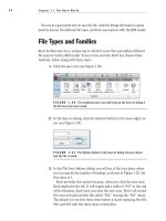
Revit Structure user interface with a project file open
Objectives
After completing this lesson, you will be able to:
■ Identify the different parts of the Revit Structure user interface.
■ Describe the Revit Structure ribbon framework.
■ State the recommended practices for using the user interface.
■ Explore the Revit Structure user interface.
Lesson: Exploring the User Interface ■ 11
The Revit Structure User Interface
Revit Structure is a powerful application that uses the building information modeling methodology and
runs on the Microsoft Windows operating system. Like most Windows applications, the user interface
of Revit Structure features a ribbon with tabs and panels, toolbars, and dialog boxes that you can use
to perform various tasks. You use the mouse to select buttons from the panels or toolbars to perform
operations.
Recent Files Window
Every time you launch Revit Structure, a startup window named Recent Files is displayed. This window
provides links to recently opened project or family files.
Recent Files window
12 ■ Chapter 2: Revit Structure Basics
Identifying the Primary User Interface Elements
The following illustration shows the ribbon in Revit with different tabs, panels, and buttons.
User Interface
Element
Description
Application Button
Opens the application menu that provides access to common tools, such as
Save, Print, and Publish.
Tab
Contains tools, settings, and standard functions. Only one tab can be active
at a time and the active tab is on top.
Panel
Groups buttons for similar functions and tools.
Expanded Panel
Expands a panel to display available actions and is indicated by an arrow
next to the panel name. You can temporarily pin an open expanded panel.
Button
Starts a tool or operation.
Split Button
Opens a drop-down with actions for the particular tool.
Dialog Launcher
Opens a dialog box.
Lesson: Exploring the User Interface ■ 13
The following illustration shows the Project Browser, status bar, View Control Bar, and other elements
of the Revit Structure user interface.
User Interface
Element
Description
Project Browser
Displays a tree view of a logical hierarchy for all views, schedules, sheets, and
families in the current project.
Status Bar
Displays the name of the family and element type when you position the
cursor over an object. Displays tips or hints when you use a comment.
View Control Bar
Provides shortcuts to commonly used view commands, such as View Scale
and Model Graphics Style.
View Window
Displays the view that you have selected in the Project Browser. Views can be
tiled or maximized to fill the entire view window.
Navigation Bar
Displays Zoom controls and opens the Steering Wheels.
View Cube
Works as an orientation control for 3D views.