Tiêu chuẩn iso 18213 4 2008
Bạn đang xem bản rút gọn của tài liệu. Xem và tải ngay bản đầy đủ của tài liệu tại đây (397.71 KB, 28 trang )
INTERNATIONAL
STANDARD
ISO
18213-4
First edition
2008-03-15
--`,,```,,,,````-`-`,,`,,`,`,,`---
Nuclear fuel technology — Tank
calibration and volume determination for
nuclear materials accountancy —
Part 4:
Accurate determination of liquid height in
accountancy tanks equipped with dip
tubes, slow bubbling rate
Technologie du combustible nucléaire — Étalonnage et détermination
du volume de cuve pour la comptabilité des matières nucléaires —
Partie 4: Détermination précise de la hauteur de liquide dans une cuve
bilan équipée de cannes de bullage, bullage lent
Reference number
ISO 18213-4:2008(E)
Copyright International Organization for Standardization
Provided by IHS under license with ISO
No reproduction or networking permitted without license from IHS
© ISO 2008
Not for Resale
ISO 18213-4:2008(E)
PDF disclaimer
This PDF file may contain embedded typefaces. In accordance with Adobe's licensing policy, this file may be printed or viewed but
shall not be edited unless the typefaces which are embedded are licensed to and installed on the computer performing the editing. In
downloading this file, parties accept therein the responsibility of not infringing Adobe's licensing policy. The ISO Central Secretariat
accepts no liability in this area.
Adobe is a trademark of Adobe Systems Incorporated.
--`,,```,,,,````-`-`,,`,,`,`,,`---
Details of the software products used to create this PDF file can be found in the General Info relative to the file; the PDF-creation
parameters were optimized for printing. Every care has been taken to ensure that the file is suitable for use by ISO member bodies. In
the unlikely event that a problem relating to it is found, please inform the Central Secretariat at the address given below.
COPYRIGHT PROTECTED DOCUMENT
© ISO 2008
All rights reserved. Unless otherwise specified, no part of this publication may be reproduced or utilized in any form or by any means,
electronic or mechanical, including photocopying and microfilm, without permission in writing from either ISO at the address below or
ISO's member body in the country of the requester.
ISO copyright office
Case postale 56 • CH-1211 Geneva 20
Tel. + 41 22 749 01 11
Fax + 41 22 749 09 47
Web www.iso.org
Published in Switzerland
ii
Copyright International Organization for Standardization
Provided by IHS under license with ISO
No reproduction or networking permitted without license from IHS
© ISO 2008 – All rights reserved
Not for Resale
ISO 18213-4:2008(E)
Contents
Page
Foreword............................................................................................................................................................ iv
Introduction ........................................................................................................................................................ v
--`,,```,,,,````-`-`,,`,,`,`,,`---
1
Scope ..................................................................................................................................................... 1
2
Physical principles involved................................................................................................................ 1
3
3.1
3.2
3.3
3.4
Required equipment, measurement conditions, and operating procedures.................................. 6
General................................................................................................................................................... 6
Tank and its measurement system ..................................................................................................... 6
Software................................................................................................................................................. 6
Operating procedures .......................................................................................................................... 8
4
4.1
4.2
4.3
4.4
4.5
Determination of height from measurements of pressure ............................................................... 8
Differential pressure ............................................................................................................................. 8
Pressure sensor calibration drift ........................................................................................................ 9
Buoyancy effects .................................................................................................................................. 9
Bubbling overpressure....................................................................................................................... 10
Liquid height ....................................................................................................................................... 11
5
Results ................................................................................................................................................. 11
Annex A (informative) Estimation of quantities that affect the determination of liquid height................ 13
Annex B (informative) Bubbling overpressure.............................................................................................. 17
Annex C (informative) Operating procedure for making pressure measurements ................................... 19
Bibliography ..................................................................................................................................................... 21
iii
© ISO 2008 – All rights reserved
Copyright International Organization for Standardization
Provided by IHS under license with ISO
No reproduction or networking permitted without license from IHS
Not for Resale
ISO 18213-4:2008(E)
Foreword
ISO (the International Organization for Standardization) is a worldwide federation of national standards bodies
(ISO member bodies). The work of preparing International Standards is normally carried out through ISO
technical committees. Each member body interested in a subject for which a technical committee has been
established has the right to be represented on that committee. International organizations, governmental and
non-governmental, in liaison with ISO, also take part in the work. ISO collaborates closely with the
International Electrotechnical Commission (IEC) on all matters of electrotechnical standardization.
International Standards are drafted in accordance with the rules given in the ISO/IEC Directives, Part 2.
The main task of technical committees is to prepare International Standards. Draft International Standards
adopted by the technical committees are circulated to the member bodies for voting. Publication as an
International Standard requires approval by at least 75 % of the member bodies casting a vote.
Attention is drawn to the possibility that some of the elements of this document may be the subject of patent
rights. ISO shall not be held responsible for identifying any or all such patent rights.
ISO 18213-4 was prepared by Technical Committee ISO/TC 85, Nuclear energy, Subcommittee SC 5,
Nuclear fuel technology.
⎯
Part 1: Procedural overview
⎯
Part 2: Data standardization for tank calibration
⎯
Part 3: Statistical methods
⎯
Part 4: Accurate determination of liquid height in accountancy tanks equipped with dip tubes, slow
bubbling rate
⎯
Part 5: Accurate determination of liquid height in accountancy tanks equipped with dip tubes, fast
bubbling rate
⎯
Part 6: Accurate in-tank determination of liquid density in accountancy tanks equipped with dip tubes
iv
Copyright International Organization for Standardization
Provided by IHS under license with ISO
No reproduction or networking permitted without license from IHS
© ISO 2008 – All rights reserved
Not for Resale
--`,,```,,,,````-`-`,,`,,`,`,,`---
ISO 18213 consists of the following parts, under the general title Nuclear fuel technology — Tank calibration
and volume determination for nuclear materials accountancy:
ISO 18213-4:2008(E)
Introduction
ISO 18213 deals with the acquisition, standardization, analysis, and use of calibration to determine liquid
volumes in process tanks for the accountancy of nuclear materials. This part of ISO 18213 is complementary
to the other parts, ISO 18213-1 (procedural overview), ISO 18213-2 (data standardization), ISO 18213-3
(statistical methods), ISO 18213-5 (fast bubbling rate) and ISO 18213-6 (in-tank determination of liquid
density).
The procedure presented herein for determining liquid height from measurements of induced pressure applies
specifically when a very slow bubbling rate is employed. A similar procedure that is appropriate for a fast
bubbling rate is given in ISO 18213-5.
Measurements of the volume and height of liquid in a process accountancy tank are often made in order to
estimate or verify the tank's calibration or volume measurement equation. The calibration equation relates the
response of the tank's measurement system to some independent measure of tank volume.
Beginning with an empty tank, calibration data are typically acquired by introducing a series of carefully
measured quantities of some calibration liquid into the tank. The quantity of liquid added, the response of the
tank's measurement system, and relevant ambient conditions such as temperature are measured for each
incremental addition. Several calibration runs are made to obtain data for estimating or verifying a tank's
calibration or measurement equation. A procedural overview of the tank calibration and volume measurement
process is given in ISO 18213-1. An algorithm for standardizing tank calibration and volume measurement
data to minimize the effects of variability in ambient conditions that prevail during the measurement period is
given in ISO 18213-2. The procedure presented in this part of ISO 18213 for determining the height of
calibration liquid in the tank from a measurement of the pressure it induces in the tank's measurement system
is a vital component of that algorithm.
In some reprocessing plants, the volume of liquid transferred into or out of a tank is determined by the levels
of two siphons. The high level corresponds to the nominal volume, and the low level to the heel volume. If the
transfer volume cannot be measured directly, then it is necessary to calibrate this volume (as described in the
previous paragraph), because the difference between the actual volume and that used for inventory
calculations will appear as a systematic error.
The ultimate purpose of the calibration exercise is to estimate the tank's volume measurement equation (the
inverse of the calibration equation), which relates tank volume to measurement system response. Steps for
using the measurement equation to determine the volume of process liquid in the tank are presented in
ISO 18213-1. The procedure presented in this part of ISO 18213 for determining the height of process liquid in
a tank from a measurement of the pressure it induces in the tank's measurement system is also a key step in
the procedure for determining process liquid volumes.
--`,,```,,,,````-`-`,,`,,`,`,,`---
v
© ISO 2008 – All rights reserved
Copyright International Organization for Standardization
Provided by IHS under license with ISO
No reproduction or networking permitted without license from IHS
Not for Resale
--`,,```,,,,````-`-`,,`,,`,`,,`---
Copyright International Organization for Standardization
Provided by IHS under license with ISO
No reproduction or networking permitted without license from IHS
Not for Resale
INTERNATIONAL STANDARD
ISO 18213-4:2008(E)
Nuclear fuel technology — Tank calibration and volume
determination for nuclear materials accountancy —
Part 4:
Accurate determination of liquid height in accountancy tanks
equipped with dip tubes, slow bubbling rate
1
Scope
This part of ISO 18213 specifies a procedure for making accurate determinations of the liquid height in
nuclear-materials-accountancy tanks that are equipped with pneumatic systems for determining the liquid
content. With such systems, gas is forced through a probe (dip tube) whose tip is submerged in the tank liquid.
The pressure required to induce bubbling is measured with a manometer located at some distance from the
tip of the probe. This procedure applies specifically when a very slow bubbling rate is employed.
A series of liquid height determinations made with a liquid of known density is required to estimate a tank's
calibration equation (see ISO 18213-1), the function that relates the elevation (height) of a point in the tank to
an independent determination of tank volume associated with that point. For accountability purposes, the
tank's measurement equation (the inverse of its calibration equation) is used to determine the volume of
process liquid in the tank that corresponds to a given determination of the liquid height.
2
Physical principles involved
The methodology in this part of ISO 18213 is based on measurements of the difference in hydrostatic
pressure at the base of a column of liquid in a tank and the pressure at its surface, as measured in a bubbler
probe inserted into the liquid. Specifically, the pressure, P, expressed in pascals, exerted by a column of liquid
at its base is related to the height of the column and the density of the liquid, in accordance with
Equation (1) 1):
P = gHMρM
(1)
where
ρM is the average density of the liquid in the column (at temperature Tm), in kg/m3;
g
1)
is the local acceleration due to gravity, in m/s2.
--`,,```,,,,````-`-`,,`,,`,`,,`---
HM is the the height of the liquid column (at temperature Tm), in m;
The subscript “M” is used to indicate the value of a temperature-dependent quantity at the temperature Tm.
1
© ISO 2008 – All rights reserved
Copyright International Organization for Standardization
Provided by IHS under license with ISO
No reproduction or networking permitted without license from IHS
Not for Resale
ISO 18213-4:2008(E)
For a liquid of known density, ρ, Equation (1) can be used to determine the height, H, of the liquid column
above a given point from (a measurement of) the pressure, P, exerted by the liquid at that point. Therefore,
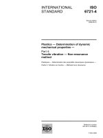
process tanks are typically equipped with bubbler probe systems to measure pressure. Components of a
typical pressure measurement system (see Figure 1) are discussed in detail in ISO 18213-1, together with a
description of the procedural aspects of a typical calibration exercise.
In practice, it is not absolute pressure that is measured, but rather the difference in pressure between the
bottom and top of the liquid column. Gas is forced through two probes to measure this differential pressure.
The tip of one probe (the long or major probe) is located near the bottom of the tank and immersed in the
liquid. The tip of the second probe (reference probe) is located in the tank above the liquid surface.
To measure the pressure, P, exerted by a column of liquid, the pressure of gas in the probe immersed in the
liquid should be measured while the gas-liquid interface is at static equilibrium. In practice, it is not possible to
measure this pressure directly because it is difficult to maintain a stable and reproducible gas-liquid interface
level in the probe. Therefore, a dynamic system is used to make measurements under conditions as close to
equilibrium as possible: Gas is forced through the probe at a very low and constant flow rate, and its pressure
is measured continuously. The fluctuation with time of these measurements (around some central value)
depends on the bubbling frequency.
Provided the gas flow rate is low and constant, the gas pressure at the tip of the major probe first increases
with time during the formation of a bubble. The release of a bubble from the tip of the probe causes a sudden
increase in the level of the bubble-liquid interface at the tip of the probe and a corresponding decrease in
pressure. For a probe with a small diameter (less than 8 mm), the pressure reaches a maximum and then
decreases slightly before the sudden drop associated with bubble separation. For probes with larger
diameters (greater than 8 mm), the maximum pressure that occurs just before bubble separation may not be
accompanied by a decrease, but may instead show a short period of relative stability followed by a sudden
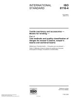
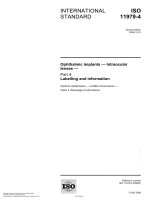
drop in response to bubble separation. The dynamics of bubble formation and release, together with their
effect on pressure in the probe, are shown in Figures 2 and 3.
Measurements of pressure are made at its maximum in the bubble formation-and-separation cycle because
this is the point at which pressure is most stable. Measuring the maximum pressure results in an overpressure
(a positive bias), denoted by (δp)max, relative to the actual pressure at the tip of the probe. A formula for
computing the overpressure, (δp)max, is given in 4.4.
Various factors, in addition to bubbling overpressure, can affect the accuracy of the height determinations that
follow from Equation (1). Temperature variations potentially have the greatest effect, especially on the
comparability of two or more measurements (such as those taken for calibration), primarily because liquid
density changes with temperature. Moreover, differences between actual pressures at the tip of the probes
and observed pressures at the manometer can result from the buoyancy effect of air and the mass of gas in
the probe lines. A general algorithm for standardizing pressure measurements that compensates for
temperature variations and other measurement factors is presented in ISO 18213-2. For the case in which
pressure measurements are made with a very slow bubbling rate, details of the pressure-to-height calculation
step of this standardization algorithm are presented in Clause 4 of this part of ISO 18213. Analogous
calculations that apply for a fast bubbling rate are given in ISO 18213-5. Procedures for estimating the
uncertainty of the resulting height determinations are given in ISO 12813-3.
--`,,```,,,,````-`-`,,`,,`,`,,`---
2
Copyright International Organization for Standardization
Provided by IHS under license with ISO
No reproduction or networking permitted without license from IHS
© ISO 2008 – All rights reserved
Not for Resale
ISO 18213-4:2008(E)
NOTE
This configuration is typical but other configurations are possible, see Reference [11] for examples.
Key
1 manometer
2
3
gas supply (N2 or air)
flowmeters
Major probe
Minor probe
Reference probe
P1
P2
Pr
r1 (primary)
r2 (secondary)
—
Height of liquid above
reference point
H1
H2
—
Elevation of pressure
gauge (manometer) above
reference point
E1
E2
Er
Elevation of reference
probe above liquid surface
h = E 1 − E r − H1
h = E 2 − E r − H2
—
Elevation of reference
point above bottom of tank
ε
ε+Sa
—
Probe designation
Reference point
a
Vertical distance (probe separation): S = H1 − H2.
Figure 1 — Elements of a typical pressure measurement system for determining liquid content
--`,,```,,,,````-`-`,,`,,`,`,,`---
3
© ISO for
2008
– All rights reserved
Copyright International Organization
Standardization
Provided by IHS under license with ISO
No reproduction or networking permitted without license from IHS
Not for Resale
ISO 18213-4:2008(E)
a) Radius of the bubbler probe, r = 3 mm
a
b
∆P = 3,7
∆P = 4,8
d
e
∆P = 7,1
∆P = 7,2
c
∆P = 5,7
f
∆P = 7,4
b) Radius of the bubbler probe, r = 10 mm
a
∆P = 2,0
c
∆P = 5,4
b
∆P = 4,4
d
∆P = 5,9
c) Radius of the bubbler probe, r = 15 mm
a
b
∆P = 1,8
∆P = 2,8
c
∆P = 5,7
∆P = mm of H2O.
r
h
--`,,```,,,,````-`-`,,`,,`,`,,`---
Key
radius of the bubbler probe, mm
bubble height, mm
Figure 2 — Evolution of a bubble in water
4
Copyright International Organization for Standardization
Provided by IHS under license with ISO
No reproduction or networking permitted without license from IHS
© ISO 2008 – All rights reserved
Not for Resale
ISO 18213-4:2008(E)
Key
t
time, s
∆P overpressure, mm of H2O
r
radius of the bubbler probe, mm
Figure 3 — Evolution of bubbling overpressure in water
5
--`,,```,,,,````-`-`,,`,,`,`,,`---
© ISO 2008 – All rights reserved
Copyright International Organization for Standardization
Provided by IHS under license with ISO
No reproduction or networking permitted without license from IHS
Not for Resale
ISO 18213-4:2008(E)
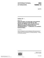
Figure 4 — End of the dip tube
3
Required equipment, measurement conditions, and operating procedures
--`,,```,,,,````-`-`,,`,,`,`,,`---
3.1
General
The pressure measurements to which this part of ISO 18213 applies are made either to calibrate a tank or to
determine the volume of process liquid it contains. The same equipment, operating procedures, and
standardization steps are used for both purposes. The elements of a pressure measurement system for
determining the liquid content of a process tank are described in detail in Clause 4 of ISO 18213-1:2007.
Measurement conditions and operating procedures for making pressure measurements to determine liquid
height are described in detail in Clause 6 of ISO 18213-1:2007.
Only aspects of equipment, measurement conditions and operating procedures that differ from those
described in ISO 18213-1 and that are specific to a slow bubbling rate are discussed in 3.2 to 3.4.
3.2
Tank and its measurement system
The tank should be connected to an air flow system that ensures a steady slow bubble rate (e.g. 2 to 4
bubbles per minute for a 15 mm diameter probe; see ISO 18213-1:2007, 4.2). For a slow bubbling rate, the
submerged probes should have a cylindrical geometry relative to the vertical axis (see Figure 4).
Experience with differential electromanometers has shown that they exhibit measurement drift. It is therefore
recommended that the instrument “zero” (i.e. the reading when the same pressure is applied at both inlets) be
read and recorded periodically. If the drift proves to be significant, this information can be used to correct the
raw data as necessary before other standardization steps are carried out.
3.3
Software
The measurement system should be connected to a micro-computer that controls operations and processes
the data into requisite form (see ISO 18213-1:2007, 4.5). The software should be adapted to the
measurement system and it should meet the following requirements.
⎯
A pressure measurement should be made under conditions as close to equilibrium as possible, therefore
at a slow enough bubbling rate (say one bubble every 15 s to 25 s for a 15 mm probe) so that the
maximum overpressure is nearly independent of the bubbling rate. The software should include a
subroutine that is capable of measuring bubbling frequency.
6
Copyright International Organization for Standardization
Provided by IHS under license with ISO
No reproduction or networking permitted without license from IHS
© ISO 2008 – All rights reserved
Not for Resale
ISO 18213-4:2008(E)
⎯
The pressure should be measured at the point of maximum overpressure (see Figures 5 and 6). The
software should therefore contain a subroutine to monitor the minimum and maximum overpressure
during the bubble cycle.
⎯
The software should monitor the pressure values in the upper third of the fluctuation range, determine the
maximum value, and select the value(s) to be retained for the height calculation. In practice, ten rapid
(5 Hz) measurements near the maximum pressure are retained to minimize the effect of measurement
fluctuations. The criteria for selecting points to be retained depend on the “bubble profile”. Therefore a
subroutine is required to record and select suitable readings. A graphical display of all pressure
measurements is most helpful for selecting suitable readings. If the maximum pressure is obtained before
the bubble breaks away, as is the case for small diameter probes (see Figure 3), ten values are selected
from the readings around this maximum. For larger diameter probes, the bubble separation causes a
rapid drop in pressure: the pressure falls below the monitoring range. In this case, the 6th through the
15th readings prior to the point of separation are used in the calculation. In all cases, the average of the
selected values is retained.
⎯
The previous three steps are carried out for five successive bubbles. The average and standard deviation
of these five points are calculated and stored.
The total time required to make the measurements for a determination of liquid height is closely linked to the
time required for the liquid surface to reach equilibrium (i.e. to stabilize) following the addition of liquid to the
tank. Less than 5 min is required to actually make the required measurements.
Key
X
Y
time, s
differential pressure, ∆P, mV
a
Overpressure, δP.
b
0,25 s.
Figure 5 — Bubble profile with a maximum before separation
--`,,```,,,,````-`-`,,`,,`,`,,`---
7
© ISO 2008 – All rights reserved
Copyright International Organization for Standardization
Provided by IHS under license with ISO
No reproduction or networking permitted without license from IHS
Not for Resale
ISO 18213-4:2008(E)
Key
X time
Y
differential pressure, ∆P
a
15 points.
b
10 points.
Maximum, M.
Minimum, m.
1/3 (M−m).
c
d
e
Figure 6 — Bubble profile without a maximum before separation
3.4
Operating procedures
Unlike the situation for a fast bubbling rate, operating procedures are required to switch the air flow from a fast
bubbling rate that is used during routine operations to a slow bubbling rate that is required during
measurement periods. This can be accomplished by means of the steps described in Annex C.
4
4.1
Determination of height from measurements of pressure
Differential pressure
When gas flows at a constant, slow rate through a dip tube immersed in liquid, a periodic fluctuation of
pressure is observed at a pressure sensor (usually located at some distance above the tank). As a bubble
forms, the pressure at the tip of the dip tube increases continuously, and then decreases abruptly when the
bubble breaks away. Therefore, if accurate measurements of pressure are required, they shall be taken under
well-defined conditions. The point at which the pressure achieves its maximum is selected because pressure
is relatively stable at this point and measurements have well-defined physical significance. A very slow gas
flow rate (2 to 4 bubbles per minute for a 15 mm diameter probe) is required to achieve a state of
quasi-equilibrium.
The bubbling pressure depends not only on the height of liquid above the tip of the dip tube, but also on the
pressure in the tank at the liquid surface. What is measured in practice is the difference between the pressure
of gas inside the submerged tube, P1(E1), and the pressure of the same gas flowing into a second tube that
vents into the vapour space at the top of the tank above the liquid surface, Pr(E1):
∆P1 = P1(E1) – Pr(E1)
(2)
--`,,```,,,,````-`-`,,`,,`,`,,`---
8
Copyright International
Organization for Standardization
Provided by IHS under license with ISO
No reproduction or networking permitted without license from IHS
© ISO 2008 – All rights reserved
Not for Resale
ISO 18213-4:2008(E)
The differential pressure, ∆P1, is measured by a manometer located at some elevation, E1, above the tip of
the major probe. One inlet of the manometer is connected to the dip tube whose tip is submerged in the tank
liquid and a second is connected to the reference probe that vents into the air space at the top of the tank.
As noted in Clause 2, various factors can affect the accuracy of the calculation for determining height from
pressure based on Equation (1). Therefore, measurements of differential pressure shall be adjusted to
compensate for variations in ambient conditions during the measurement period before they can be converted
into accurate measures of liquid height. Appropriate corrections are discussed in 4.2 to 4.4.
4.2
Pressure sensor calibration drift
Pressure fluctuations (e.g. drift) over time may result from a zero shift in the pressure sensors (manometers).
Therefore, it is necessary to make measurements of the instrument “zero” before and at regular intervals
during a series of measurements (e.g. every hour for instance depending on the instrument). This is done by
equalizing the pressure at both inlets of the manometer and recording the results. These measurements
should be used to correct pressure measurement as necessary for the effect of zero drift (which can exceed
10 Pa). Excellent results can often be obtained simply by making a linear adjustment (shift) to the observed
pressure measurements.
In general, however, the response of the pressure sensor and its measurement chain (sensor and voltmeter)
is not a linear function of pressure. Thus, it may be necessary to develop a suitable model of measurement
system response. A low-order polynomial will typically be adequate for this purpose.2)
4.3
Buoyancy effects
After pressure measurements have been corrected for instrument drift, they can in principle be converted into
determinations of height, H1,M, by means of Equation (1) rewritten in accordance with Equation (3):
H1,M = ∆P1/(gρM)
(3)
where
ρM is the average density of the liquid in the tank at its measurement temperature, Tm.
However, according to the principle of Archimedes, it is in fact more accurate to use Equation (4):
H1,M = ∆P1/[g(ρM − ρg,r)]
(4)
where
ρg,r is the density of the medium (gas) in which the measurements are made, typically air in the tank
above the liquid surface.
Moreover, the differential pressure, ∆P1, is measured by a pressure sensor that is not located at the liquid
surface, but typically at a markedly different elevation. Thus, the weight of the gas column in the pneumatic
lines should also be taken into account. Because pressure equilibrium exists on both sides of the liquid-gas
interface, one can write
P1(E1) + gE1ρg,1 = Pr(E1) + gErρ g,r + g(E1 – Er – H1,M) ρa,s + gH1,MρM + (δp)max
(5)
2) With Crouzet 43 or 44 manometers, for example, the response is described by a quadratic polynomial that reduces
possible bias of several pascals to less than one pascal.
--`,,```,,,,````-`-`,,`,,`,`,,`---
9
© ISO 2008 – All rights reserved
Copyright International Organization for Standardization
Provided by IHS under license with ISO
No reproduction or networking permitted without license from IHS
Not for Resale
ISO 18213-4:2008(E)
where
H1,M
is the height of liquid in the tank above the tip of the bubbling (major) probe 3);
E1
is the elevation of the manometer (pressure sensor) above the tip of the major probe;
Er
is the elevation of the manometer above the tip of the reference probe;
ρg,1
is the density of the bubbling gas at pressure P1 in the major probe;
ρg,r
is the density of the bubbling gas at pressure Pr in the reference probe;
ρa,s
is the density of air in the tank above the liquid surface at pressure Pr;
(δp)max
is the maximum overpressure, relative to that at the tip of the probe, observed during the
bubbling process.
It follows from Equation (5) that
H1,M = [P1(E1) − Pr(Er) + gE1ρg,1 – gE1ρa,s – gErρ g,r + gErρa,s − (δp)max] / [g(ρM – ρa,s)]
= [∆P1 + gE1(ρg,1 – ρa,s) – gEr(ρg,r – ρa,s) − (δp)max] / [g(ρM – ρa,s)]
(6)
If the bubbling gas is air, then ρg,1 = ρa,1 and ρg,r = ρa,r. In this case, Equation (6) can be written as
H1,M = [∆P1 + gE1(ρa,1 – ρa,s) – gEr(ρa,r – ρa,s) − (δp)max] / [g(ρM – ρa,s)]
(7)
The expression for H1,M in Equation (7) includes adjustments to the measured differential pressure, ∆P1, that
compensate for the buoyancy of the medium (air) in which the measurements are made, the weight of the gas
in the pneumatic lines, and the maximum bubbling overpressure at the tip of the submerged probe. A formula
for computing the maximum overpressure, (δp)max, is given in 4.4. Other quantities on the right-hand side of
Equation (7) may be computed by means of formulae given in Annex A.
Equation (7) is used to determine liquid heights from measurements of pressure for both tank calibration and
volume determination.
4.4
Bubbling overpressure
Measurements of pressure are made at the maximum in the bubble formation-and-separation cycle because
the pressure is most stable at this point. In Equation (7), the maximum overpressure, relative to the actual
pressure at the tip of the probe, is denoted by (δp)max. For aqueous solutions, it is shown in Annex B that this
overpressure can be described by the following empirical relationship:
(δp)max = (grρM) / [rc0,5/2 − 0,14] = (2grρM) / [rc0,5 − 0,28]
(8)
where
r
is the radius of fixation of the bubble;
c = g(ρM − ρg)/σ
(9)
3) The subscript “1” is used in this part of ISO 18213 to indicate quantities that refer to the major probe (see Figure 1).
The steps for standardizing data for a second probe are completely analogous.
10
--`,,```,,,,````-`-`,,`,,`,`,,`---
Copyright International Organization for Standardization
Provided by IHS under license with ISO
No reproduction or networking permitted without license from IHS
© ISO 2008 – All rights reserved
Not for Resale
ISO 18213-4:2008(E)
where
ρg is the the density of gas in pressure line (ρg = ρa,1 if the bubbling gas is air);
σ
is the the surface tension at the liquid-gas interface.
The normalized overpressure (expressed in terms of liquid height), given by Equation (8), depends on the
liquid in the tank through c, as given by Equation (9). This quantity is essentially independent of pressure and
is therefore also independent of the height of liquid in the tank. The quantity c varies with temperature as the
ratio (ρM/σ)0,5.
4.5
Liquid height
Taken together, Equations (7) to (9) yield an estimate of liquid height, H1,M, that is valid at temperature Tm, the
temperature of the liquid in the tank at the time of measurement.
The accuracy of height determinations obtained by means of Equations (7) to (9) is limited by how well the
density of the measured liquid is determined at the prevailing temperature. It is also important to note that
H1,M is the height of the liquid in the tank only at the measurement temperature. In particular, H1,M is not the
height of the same liquid at some other temperature.
Some of the effects identified in Equations (7) to (9) may be quite small. Whether or not they must be taken
into account in a particular situation depends on the capability of the tank's measurement system (e.g.
manometer) and established measurement accuracy requirements. If the quantities in these equations must
be taken into account, they should be measured whenever possible. However, an algorithm is given in
Annex A for estimating these quantities when measurements are unavailable. Under normal operating
conditions, use of the suggested default values in lieu of actual measurements will provide acceptable results
in nearly all situations.
5
Results
Starting with a measure of the pressure required to induce bubble formation at the tip of a probe submerged in
the liquid in an accountancy tank, the standardization procedure described in Clause 4 yields an accurate
measure of the height of the column of liquid exerting the pressure. With high-precision manometers and good
technique applied under stable conditions, it is possible to achieve relative accuracies for individual height
determinations in the range of 0,01 % to 0,02 % 4), 5) for pressures of approximately 10 000 Pa or greater.
This degree of accuracy corresponds to 1 Pa to 2 Pa, or approximately 0,1 mm to 0,2 mm, for a 1 m column of
water.
--`,,```,,,,````-`-`,,`,,`,`,,`---
The accuracy of liquid height determinations obtained from Equations (7) to (9) is limited by the accuracy of
available measurements of liquid density. Thus, to successfully employ the methods of this part of ISO 18213,
the density of the measured liquid must be determined with sufficient accuracy at its measurement
temperature. Therefore, a liquid (such as water) whose density has been very accurately determined at all
measurement temperatures is required for calibration. In tanks equipped with two or more dip tubes of
differing lengths, it is possible to make accurate determinations of the densities of process liquids from in-tank
measurements. The first step is to accurately determine the vertical separation between the two probes (i.e. to
calibrate their separation) using a suitable calibration liquid. The probe separation calibration can in turn be
used to determine the density of the process liquid in question. Details of this two-stage procedure are
presented in ISO 18213-6.
4) In ISO 18213, all estimates of accuracy are expressed in terms of the half-width of two standard deviation (95 %)
confidence intervals. Thus, the assertion here is that relative standard deviations for individual measurements in the range
0,005 % to 0,01 % are possible.
5) Depending on the resolution of the manometer, it may be necessary to average the results of several height
determinations to achieve this level of precision (see ISO 18213-1:2007, 6.6.3).
11
© ISO 2008 – All rights reserved
Copyright International Organization for Standardization
Provided by IHS under license with ISO
No reproduction or networking permitted without license from IHS
Not for Resale
ISO 18213-4:2008(E)
Because liquid density changes with temperature, a height measurement, H1,M, obtained from Equations (7)
to (9), corresponds to the height of liquid in the tank only at the measurement temperature, Tm. In particular,
the height of the liquid used to determine H1,M is not equal to H1,M at any other temperature. Moreover,
process tanks do not in general have constant cross-sectional areas, so heights determined for a liquid at one
temperature are not directly comparable to those determined at other temperatures, even for the same liquid.
Therefore, except in very special cases, it is not appropriate to use an equation of the form H2 = H1.ρ1/ρ2 to
make thermal adjustments. In particular, the ratio of the densities of water at two temperatures should not be
used to infer the height of process liquid at one temperature from its height at another because unacceptably
large errors can result. To ensure that the resulting height determinations are comparable, the standardization
steps in Clause 4 should be applied individually to each measurement of pressure.
The value of H1,M obtained from Equations (7) to (9) is valid only at the measurement temperature, Tm.
Therefore, it is necessary to standardize the height measurements made at differing temperatures to a fixed
reference temperature to compensate for thermally induced changes in the tank and dip tubes.
Standardization of several measurements at a fixed reference temperature is accomplished as follows. When
the liquid in the tank is at temperature Tm, then H1,M determines a point on the tank wall at the liquid surface 6).
If the tank temperature now changes to Tr, then the elevation of the indicated point (but not the height of the
liquid used to determine H1,M) above the tip of the probe changes to
H1,r = H1,M/(1+ α∆Tm)
(10)
where ∆Tm = Tm − Tr and α is the linear (thermal) coefficient of expansion for the tank and its probes. To
ensure comparability in the presence of temperature variations, all height determinations obtained from
Equations (7) to (9) should be standardized to a convenient reference temperature (e.g. Tr = 25 °C or
Tr = 31 °C) by means of Equation (10). See ISO 18213-2:2007, 5.3 for additional details.
An equation has been developed by Jones [8] that relates the differential pressure exerted by a column of
water at one temperature to the pressure it exerts at another temperature. A paper by Jones and Crawford [10]
describes an experiment which shows that the calculated results are in good agreement with the observed
results. For water, this eliminates the need to apply the standardization steps of Clause 4 individually to each
pressure measurement. Similar equations can be developed for other liquids, but a safe alternative is to
always make the corrections indicated by Equations (7) to (9) for each measurement of pressure.
An algorithm is presented in ISO 18213-2 for standardizing a set of data and using these (standardized) data
to calibrate a tank (i.e. to estimate the relationship between the response of the tank's measurement system
and some independent measure of its liquid content). The procedure specified in this part of ISO 18213 for
determining liquid height from pressure is a key step in the overall standardization-and-calibration process.
Steps in this part of ISO 18213 are also required when the calibration equation (or its inverse) is subsequently
used to determine process liquid volumes (see Clause 7 of ISO 18213-1:2007).
6)
--`,,```,,,,````-`-`,,`,,`,`,,`---
12
H1,M denotes the height of the point determined by means of Equations 7 to 9 for a liquid at temperature Tm.
Copyright International Organization for Standardization
Provided by IHS under license with ISO
No reproduction or networking permitted without license from IHS
© ISO 2008 – All rights reserved
Not for Resale
ISO 18213-4:2008(E)
Annex A
(informative)
Estimation of quantities that affect the determination of liquid height
A.1 Introduction
Procedures are presented in this annex for estimating the quantities required to determine liquid height, H1,M,
from differential pressure, ∆P1, by means of Equations (7) to (9). In these equations, heights are expressed in
metres, pressures are expressed in pascals, and densities are expressed in kilograms per cubic metre. The
local acceleration due to gravity, g, is expressed in metres par second squared.
A.2 Liquid density, ρ
Any liquid compatible with the process liquid can be used for tank calibration, provided that accurate
measurements of its density can be obtained at all measurement temperatures. Demineralized water is a
preferred calibration liquid because its density is well known and can be accurately determined at all
temperatures of interest. Equation (A.1) gives very accurate determinations of the density of air-free (freshly
distilled) water, ρM, in kilograms per cubic metre, for temperatures T = Tm between 4 °C and 40 °C:
ρM = A + BT + CT2 + DT3 + ET4 + FT5
(A.1)
where
A = 999,843 22
B = 6,684 416 × 10−2
C = −8,903 070 × 10−3
D = 8,797 523 × 10−5
E = −8,030 701 × 10−7
F = 3,596 363 × 10−10
For temperatures between 3 °C and 30 °C, the estimated residual standard deviation for this fit is less than
0,001 kg/m3. For other temperatures between 1 °C and 40 °C, the reported standard deviation does not
exceed 0,001 4 kg/m3.
Water can become saturated after being exposed to air for a relatively short period of time (approximately
15 h). If necessary, the density of air-saturated water at 1 atm can be calculated by adding the following
correction to the estimate obtained from Equation (A.1):
∆ρM = −4,873 × 10−3 + 1,708 × 10−4T – 3,108 × 10−6 T2
(A.2)
--`,,```,,,,````-`-`,,`,,`,`,,`---
Equation (A.2) is applicable for temperatures between 0 °C and 20 °C. The correction for air saturation is
−0,002 70 kg/m3 at 20 °C and its effect diminishes with increasing temperature. The estimated total
uncertainty of values calculated with Equation (A.2) is reported as 2 × 10⁻⁴ kg/m3 at the 99 % confidence level.
Thus, the effect of air saturation at temperatures greater than 20 °C can safely be ignored for most safeguards
applications.
13
© ISO 2008 – All rights reserved
Copyright International Organization for Standardization
Provided by IHS under license with ISO
No reproduction or networking permitted without license from IHS
Not for Resale
ISO 18213-4:2008(E)
Equations (A.1) and (A.2) are based on a recent re-determination of the density of water [11]. Equation (A.1),
or Equation (A.1) and Equation (A.2) in combination, can be used to compute the density of water with
sufficient accuracy and precision for safeguards purposes.
If some liquid other than water is used for calibration, then its density must be determined with suitable
accuracy at all measurement temperatures before Equations (7) to (9) (see 4.3 and 4.4) can be successfully
applied.
--`,,```,,,,````-`-`,,`,,`,`,,`---
Likewise, the use of Equations (7) to (9) to determine the height of some process liquid in the tank requires an
accurate measure of its density at the measurement temperature. A method for making accurate
determinations of liquid density from in-tank measurements is presented in ISO 18213-6.
A.3 Density of gas in the pressure lines
A.3.1 General formula for air density
The density of the gas in the pressure lines is required to evaluate some of the terms in Equations (7) to (9). If
the gas is air, then its density, ρa, in kilograms per cubic metre, can be determined from its temperature,
pressure and relative humidity by means of Equation (A.3) [9]:
⎛ −5 315,56 ⎞ ⎤
⎡
⎜
⎟⎥
(0,003 484 7) ⎢
8
ρa =
P − 6,653 06 × 10 × U × e ⎝ T + 273,15 ⎠ ⎥
⎢
(T + 273,15)
⎢⎣
⎥⎦
(A.3)
where
P
is the pressure, in pascals;
U
is the relative humidity of the air, in percent saturation;
T
is the average temperature of the gas, in degrees Celsius.
If the bubbling gas is not air (e.g. N2), then a suitable alternative to Equation (A.3) is required. In any case,
Equation (A.3) can be used to estimate the density of the air in the tank above the liquid surface.
A.3.2 Density of air in the major probe line, ρa,1
Measurements of P (Pa), U (% saturation), and T (°C) are required to use Equation (A.3) for estimating the
density of air in the major probe line. If measurements are not available, the following default values will yield
acceptable results in nearly all cases.
A suitable default value for P is
P = ∆P1 + Ps
(A.4)
where
∆P1 is the observed differential pressure at the manometer;
Ps is the barometric pressure minus off-gas pressure.
Standard atmospheric pressure at sea level is 1,013 25 × 105 Pa, and typical off-gas pressure is 500 Pa,
equivalent to the pressure exerted by a 50 mm column of water. If these values are used in Equation (A.4),
the result is
P = ∆P1 + 1,008 25 × 105
(A.5)
14
Copyright International Organization for Standardization
Provided by IHS under license with ISO
No reproduction or networking permitted without license from IHS
© ISO 2008 – All rights reserved
Not for Resale