Tiêu chuẩn iso 08116 4 2008
Bạn đang xem bản rút gọn của tài liệu. Xem và tải ngay bản đầy đủ của tài liệu tại đây (199.05 KB, 16 trang )
INTERNATIONAL
STANDARD
ISO
8116-4
Third edition
2008-12-15
Textile machinery and accessories —
Beams for winding —
Part 4:
Test methods and quality classification of
flanges for weaver’s beams, warper’s
beams and sectional beams
Matériel pour l'industrie textile — Ensouples pour enroulement —
Partie 4: Méthodes d’essai et classes de qualité pour les joues
d’ensouples de tissage, d’ourdissoirs et sectionnelles
Reference number
ISO 8116-4:2008(E)
--`,,```,,,,````-`-`,,`,,`,`,,`---
Copyright International Organization for Standardization
Provided by IHS under license with ISO
No reproduction or networking permitted without license from IHS
Not for Resale
© ISO 2008
ISO 8116-4:2008(E)
PDF disclaimer
This PDF file may contain embedded typefaces. In accordance with Adobe’s licensing policy, this file may be printed or viewed but
shall not be edited unless the typefaces which are embedded are licensed to and installed on the computer performing the editing. In
downloading this file, parties accept therein the responsibility of not infringing Adobe’s licensing policy. The ISO Central Secretariat
accepts no liability in this area.
Adobe is a trademark of Adobe Systems Incorporated.
Details of the software products used to create this PDF file can be found in the General Info relative to the file; the PDF-creation
parameters were optimized for printing. Every care has been taken to ensure that the file is suitable for use by ISO member bodies. In
the unlikely event that a problem relating to it is found, please inform the Central Secretariat at the address given below.
--`,,```,,,,````-`-`,,`,,`,`,,`---
COPYRIGHT PROTECTED DOCUMENT
© ISO 2008
All rights reserved. Unless otherwise specified, no part of this publication may be reproduced or utilized in any form or by any means,
electronic or mechanical, including photocopying and microfilm, without permission in writing from either ISO at the address below or
ISO’s member body in the country of the requester.
ISO copyright office
Case postale 56 • CH-1211 Geneva 20
Tel. + 41 22 749 01 11
Fax + 41 22 749 09 47
Web www.iso.org
Published in Switzerland
ii
Copyright International Organization for Standardization
Provided by IHS under license with ISO
No reproduction or networking permitted without license from IHS
© ISO 2008 – All rights reserved
Not for Resale
ISO 8116-4:2008(E)
Foreword
ISO (the International Organization for Standardization) is a worldwide federation of national standards bodies
(ISO member bodies). The work of preparing International Standards is normally carried out through ISO
technical committees. Each member body interested in a subject for which a technical committee has been
established has the right to be represented on that committee. International organizations, governmental and
non-governmental, in liaison with ISO, also take part in the work. ISO collaborates closely with the
International Electrotechnical Commission (IEC) on all matters of electrotechnical standardization.
International Standards are drafted in accordance with the rules given in the ISO/IEC Directives, Part 2.
The main task of technical committees is to prepare International Standards. Draft International Standards
adopted by the technical committees are circulated to the member bodies for voting. Publication as an
International Standard requires approval by at least 75 % of the member bodies casting a vote.
Attention is drawn to the possibility that some of the elements of this document may be the subject of patent
rights. ISO shall not be held responsible for identifying any or all such patent rights.
ISO 8116-4 was prepared by Technical Committee ISO/TC 72, Textile machinery and accessories,
Subcommittee SC 3, Machinery for fabric manufacturing including preparatory machinery and accessories.
This third edition cancels and replaces the second edition (ISO 8116-4:1995), which has been technically
revised.
ISO 8116 consists of the following parts, under the general title Textile machinery and accessories — Beams
for winding:
--`,,```,,,,````-`-`,,`,,`,`,,`---
⎯
Part 1: General vocabulary
⎯
Part 2: Warper’s beams
⎯
Part 3: Weaver’s beams
⎯
Part 4: Test methods and quality classification of flanges for weaver’s beams, warper’s beams and
sectional beams
⎯
Part 5: Sectional beams for warp knitting machines
⎯
Part 6: Beams for ribbon weaving and ribbon knitting
⎯
Part 7: Beams for dyeing slivers, rovings and yarns
⎯
Part 8: Definitions of run-out tolerances and methods of measurement
⎯
Part 9: Dyeing beams for textile fabrics
iii
© ISO 2008 – All rights reserved
Copyright International Organization for Standardization
Provided by IHS under license with ISO
No reproduction or networking permitted without license from IHS
Not for Resale
--`,,```,,,,````-`-`,,`,,`,`,,`---
Copyright International Organization for Standardization
Provided by IHS under license with ISO
No reproduction or networking permitted without license from IHS
Not for Resale
INTERNATIONAL STANDARD
ISO 8116-4:2008(E)
Textile machinery and accessories — Beams for winding —
Part 4:
Test methods and quality classification of flanges for weaver’s
beams, warper’s beams and sectional beams
1
Scope
This part of ISO 8116 specifies the test procedure for flanges for weaver’s beams, warper’s beams and
sectional beams and the quality classes in this respect.
2
Normative references
The following referenced documents are indispensable for the application of this document. For dated
references, only the edition cited applies. For undated references, the latest edition of the referenced
document (including any amendments) applies.
ISO 8116-1, Textile machinery and accessories — Beams for winding — Part 1: General vocabulary
ISO 8116-2:2008, Textile machinery and accessories — Beams for winding — Part 2: Warper’s beams
ISO 8116-3, Textile machinery and accessories — Beams for winding — Part 3: Weaver’s beams
ISO 8116-5:2008, Textile machinery and accessories — Beams for winding — Part 5: Sectional beams for
warp knitting machines
3
Terms and definitions
For the purposes of this document, the terms and definitions given in ISO 8116-1 and the following apply.
3.1
quality class
classification of beam flanges according to their deformation behaviour under load
4
--`,,```,,,,````-`-`,,`,,`,`,,`---
3.2
maximum test load
Fmax
maximum value of load applied to the beam flange during testing according to its quality class
Quality classification
Beam flanges are classified according to four quality classes. The designation of the quality classes is Q1, Q2,
Q3 or Q4.
Depending on the quality class, the beam flanges are loaded with different ultimate loads. These limit values
are given in Clause 6.
For examples of application by quality class, see Annex A.
1
© ISO 2008 – All rights reserved
Copyright International Organization for Standardization
Provided by IHS under license with ISO
No reproduction or networking permitted without license from IHS
Not for Resale
ISO 8116-4:2008(E)
5
Test methods
5.1
Principle
The beam flange is subjected to a test load and the resulting deformation is measured.
For weaver’s beams, the test load is applied to the flange via a beam barrel. For warper’s beams and
sectional beams, the load is applied to the beam flange via a pressure plate. A pressure ring with a defined
inner diameter is used as an anvil.
The permanent deformation and the plastic deformation of the flange shall not exceed the defined limit values
when the maximum load is applied.
5.2
Apparatus
5.2.1
Press device, with indications for the application of the test load.
5.2.2
Three dial gauges, for determination of deformation of the flange with an accuracy of 0,01 mm.
5.2.3 Measurement device, for joint installation of the three dial gauges on the bearing device, in an angle
of 120° each.
5.2.4
Steel pressure ring.
5.2.5
Beam barrel, for load application (for weaver’s beams).
5.2.6
Pressure plate, for load application (for warper’s beams and sectional beams).
5.3
Testing configuration
--`,,```,,,,````-`-`,,`,,`,`,,`---
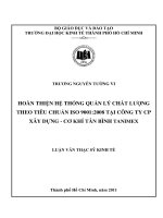
For measurement of flange deformation, three dial gauges are installed on the bearing device by means of the
measurement device. These are used to measure the relative path between the outer diameter of the beam
barrel d2 and the circle diameter d1 − 20 mm. The dial gauges are staggered by 120°. The testing
configuration for weaver’s beams is given in Figure 1. The testing configurations for warper’s beams are given
in Figure 2 and Figure 3. The testing configuration for sectional beams is given in Figure 4.
2
Copyright International Organization for Standardization
Provided by IHS under license with ISO
No reproduction or networking permitted without license from IHS
© ISO 2008 – All rights reserved
Not for Resale
ISO 8116-4:2008(E)
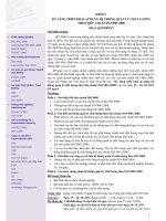
Dimensions in millimetres
Key
1
2
dial gauge (schematic representation)
beam barrel
d1 outer diameter of weaver’s beam flange
d2 outer diameter of weaver’s beam barrel
3
4
threaded ring
weaver’s beam
Di
5
steel pressure ring
inner diameter of pressure ring
Figure 1 — Testing configuration for weaver’s beam
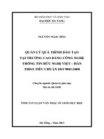
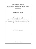
Dimensions in millimetres
Key
1 dial gauge (schematic representation)
d1 outer diameter of warper’s beam flange
2
3
pressure plate
warper’s beam
d2 outer diameter of warper’s beam barrel
Di inner diameter of pressure ring
4
5
steel pressure ring
warper’s beam barrel (not required for pressure test)
Figure 2 — Testing configuration for warper’s beam flange with shaft (Type A)
and cylindrical hole (Type B)
--`,,```,,,,````-`-`,,`,,`,`,,`---
3
© ISO 2008 – All rights reserved
Copyright International Organization for Standardization
Provided by IHS under license with ISO
No reproduction or networking permitted without license from IHS
Not for Resale
ISO 8116-4:2008(E)
The diameter of the pressure plate for load application for warper’s beams of Type A and Type B is defined as
d2 − 20 mm (see Figure 2).
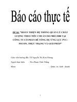
Key
1 dial gauge (schematic representation)
d1 outer diameter of warper’s beam flange
2
3
pressure plate
warper’s beam flange
d2 outer diameter of warper’s beam barrel
Di inner diameter of pressure ring
4
5
steel pressure ring
warper’s beam barrel (not required for pressure test)
Figure 3 — Testing configuration for warper’s beam flange with tooth cone — Type C
The diameter of the pressure plate for load application for warper’s beams with tooth cone (Type C) is defined
using d5 in accordance with ISO 8116-2:2008, Table 2.
4
Copyright International Organization for Standardization
Provided by IHS under license with ISO
No reproduction or networking permitted without license from IHS
© ISO 2008 – All rights reserved
Not for Resale
--`,,```,,,,````-`-`,,`,,`,`,,`---
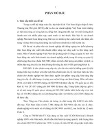
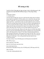
Dimensions in millimetres
ISO 8116-4:2008(E)
Dimensions in millimetres
Key
1 dial gauge (schematic representation)
pressure plate
sectional beam flange
4
5
steel pressure ring
sectional beam barrel (not required for pressure test)
d2 outer diameter of sectional beam barrel
d3 bore diameter of flange (see also ISO 8116-5:2008,
Figure 1)
Di inner diameter of pressure ring
Figure 4 — Testing configuration for sectional beams
--`,,```,,,,````-`-`,,`,,`,`,,`---
d1 outer diameter of sectional beam flange
2
3
The diameter of the pressure plate for load application for sectional beams of knitting machines is defined
using d3 + 40 mm.
5.4
Performance
The measurement device is installed as described in 5.3. The beam flange, the pressure ring and the
pressure plate, if required, are aligned centrally below the press loading pad.
Stepwise loading of the flange shall occur in steps to be chosen usefully.
The load applied and the deformation are determined at the test area for each loading step. The value of the
total deformation is calculated from the average of the three measurement values. After each load step,
unloading of the flange is optional.
After unloading, the values indicated are read with the dial gauge. The values for the plastic deformation are
calculated from the average of the three measurement values.
Then loading is applied with the next higher load value.
This procedure is repeated until the defined maximum test load of the corresponding quality class as given in
Equation (2) and Table 1 is reached.
The beam flange corresponds to the quality class if the value measured for the total deformation and the value
measured for the plastic deformation are below the values obtained when using Equation (3) and Equation (4).
5
© ISO 2008 – All rights reserved
Copyright International Organization for Standardization
Provided by IHS under license with ISO
No reproduction or networking permitted without license from IHS
Not for Resale
ISO 8116-4:2008(E)
Once the given maximum load has been achieved, the plastic deformation shall be measured after unloading.
Subsequently, the dial gauges are set to “zero”. The maximum test load shall again be applied. After
unloading, only an insignificantly low residual deformation value shall be read.
6
Pressure ring diameter, maximum test load and limit values of deformation
The diameter of the pressure ring, maximum test load and limit values of deformation shall be calculated using
Equations (1), (2) or (3) for any flange geometry:
⎯
for weaver’s beams in accordance with ISO 8116-3, the values are given in Table 2;
⎯
for warper’s beams in accordance with ISO 8116-2, the values are given in Table 3;
⎯
for sectional beams in accordance with ISO 8116-5, the values are given in Table 4.
6.1
Pressure ring diameter
The diameter of the pressure ring is calculated, depending on the inner and outer diameter of the beam flange,
using Equation (1):
Di =
2 d 13 − d 23
×
3 d 12 − d 22
(1)
where
Di
is the inner diameter of the pressure ring, in millimetres;
d1
is the outer diameter of the beam flange, in millimetres;
d2
is the outer diameter of the beam barrel, in millimetres.
The tolerance for the diameter of the pressure ring, Di, may not exceed ± 1 mm.
NOTE
Equation (1) corresponds to the centre of the diameter of a circular ring segment on the condition that the
angle of the circular ring segment reaches zero. In practice, the actual load on the beam flange is different, depending on
the winding.
6.2
Maximum test load
Depending on the quality class, the maximum test load is calculated from the maximum test load given in
Table 1 multiplied by the maximum winding area of the beam flange, using Equation (2).
Fmax = Amax × pi
(2)
where
Fmax
is the maximum test load, in kilonewtons;
Amax
is the maximum winding area of the beam flange, in square millimetres;
Amax =
pi
π
× ( d 12 − d 22 )
4
is the maximum test load, in megapascals.
--`,,```,,,,````-`-`,,`,,`,`,,`---
6
Copyright International Organization for Standardization
Provided by IHS under license with ISO
No reproduction or networking permitted without license from IHS
© ISO 2008 – All rights reserved
Not for Resale
ISO 8116-4:2008(E)
6.3
Quality class
Maximum test load pi
MPa
Q1
0,08
Q2
0,2
Q3
0,5
Q4
0,8
Limit value of deformation
The limit value of total deformation at maximum test load is calculated, depending on the geometry of the
flange, using Equation (3):
f tot −lim =
4 × (d1 − d 2 )
1 000
(3)
where
ftot-lim
is the admissible total flange deformation, in millimetres;
d1
is the outer diameter of the beam flange, in millimetres;
d2
is the outer diameter of the beam barrel, in millimetres.
The limit value of the plastic deformation at maximum test load amounts to a quarter of the limit value of total
deformation in the case of initial loading of the beam flange.
If the maximum test load is again applied to the beam flange, as shown in Equation (4), the proportion of
plastic deformation shall be insignificantly low.
f
(d − d 2 )
f plast −lim = tot −lim = 1
4
1 000
(4)
where
fplast-lim is the admissible plastic flange deformation, in millimetres;
6.4
ftot-lim
is the admissible total flange deformation, in millimetres;
d1
is the outer diameter of the beam flange, in millimetres;
d2
is the outer diameter of the beam barrel, in millimetres.
Values for weaver’s beams
The values for the pressure ring diameter, the maximum test load and the limit values of deformation for
weaver’s beams in accordance with ISO 8116-3 are given in Table 2.
7
© ISO 2008 – All rights reserved
Copyright International Organization for Standardization
Provided by IHS under license with ISO
No reproduction or networking permitted without license from IHS
Not for Resale
--`,,```,,,,````-`-`,,`,,`,`,,`---
Table 1 — Limit loads of quality classes
ISO 8116-4:2008(E)
Table 2 — Test values for weaver’s beams in accordance with ISO 8116-3
Flange geometry
6.5
Pressure
ring inner
diameter
Maximum test load of quality Class Q1
Limit values of flange
deformations
d1
d2
Di
FmaxQ1
FmaxQ2
FmaxQ3
FmaxQ4
ftot-lim
fplast-lim
mm
mm
mm
kN
kN
kN
kN
mm
mm
500
150
356
14
36
89
143
1,4
0,4
600
150
420
21
53
133
212
1,8
0,5
700
150
484
29
73
184
294
2,2
0,6
750
150
517
34
85
212
339
2,4
0,6
800
150
549
39
97
242
388
2,6
0,7
800
216
564
37
93
233
373
2,3
0,6
850
216
596
42
106
265
425
2,5
0,6
900
216
628
48
120
300
480
2,7
0,7
950
216
660
54
134
336
538
2,9
0,7
1 000
269
705
58
146
364
583
2,9
0,7
1 250
269
865
94
234
585
936
3,9
1,0
1 400
269
962
119
297
741
1 186
4,5
1,1
1 500
269
1 027
137
342
855
1 368
4,9
1,2
Values for warper’s beams
The values for the pressure ring diameter, the maximum test load and the limit values of deformation for
warper’s beams in accordance with ISO 8116-2 are given in Table 3.
--`,,```,,,,````-`-`,,`,,`,`,,`---
8
Copyright International Organization for Standardization
Provided by IHS under license with ISO
No reproduction or networking permitted without license from IHS
© ISO 2008 – All rights reserved
Not for Resale
ISO 8116-4:2008(E)
Table 3 — Test values for warper’s beams in accordance with ISO 8116-2
Flange geometry
Maximum test load of quality class Q1
Limit values of flange
deformations
d1
d2
Di
FmaxQ1
FmaxQ2
FmaxQ3
FmaxQ4
ftot-lim
fplast-lim
mm
mm
mm
kN
kN
kN
kN
mm
mm
800
300
588
35
86
216
346
2,0
0,5
800
320
594
34
84
211
338
1,9
0,5
815
300
597
36
90
225
361
2,1
0,5
815
320
603
35
88
221
353
2,0
0,5
900
300
650
45
113
283
452
2,4
0,6
900
320
656
44
111
278
445
2,3
0,6
915
300
659
47
117
293
469
2,5
0,6
915
320
665
46
115
289
462
2,4
0,6
1 000
300
713
57
143
357
572
2,8
0,7
1 000
320
718
56
141
352
564
2,7
0,7
1 015
300
722
59
148
369
591
2,9
0,7
1 015
320
728
58
146
364
583
2,8
0,7
1 100
360
793
68
170
424
679
3,0
0,7
1 250
300
872
93
231
578
925
3,8
1,0
1 250
320
877
92
229
573
917
3,7
0,9
1 250
400
898
88
220
551
881
3,4
0,9
1 400
450
1 006
110
276
690
1 104
3,8
1,0
NOTE
6.6
Pressure
ring inner
diameter
To achieve the quality classes Q3 and Q4, deviations from the geometric provisions given in ISO 8116-2 are possible.
Values for sectional beams for knitting machines
The values for the pressure ring diameter, the maximum test load and the tolerances of deformation for
sectional beams of knitting machines in accordance with ISO 8116-5 are given in Table 4.
Table 4 — Test values for sectional beams in accordance with ISO 8116-5
Flange geometry
Pressure
ring inner
diameter
Maximum test load of quality class Q1
Limit values of flange
deformations
--`,,```,,,,````-`-`,,`,,`,`,,`---
d1
d2
Di
FmaxQ1
FmaxQ2
FmaxQ3
FmaxQ4
ftot-lim
fplast-lim
mm
mm
mm
kN
kN
kN
kN
mm
mm
355
110
254
7
18
45
72
1,0
0,2
532
196
390
15
14
34
55
0,6
0,2
762
298
564
31
77
193
309
1,9
0,5
1 000
360
730
55
137
342
547
2,6
0,6
9
© ISO 2008 – All rights reserved
Copyright International Organization for Standardization
Provided by IHS under license with ISO
No reproduction or networking permitted without license from IHS
Not for Resale
ISO 8116-4:2008(E)
Annex A
(informative)
Examples of application by quality class
A.1 Choice of quality class
In using beam flanges, the quality class is chosen depending on the load. See Table A.1 for examples of
quality class for different yarn types and mean winding parameters
A.2 Effect of winding parameters on the loading
The following winding parameters have a decisive effect on the loading of the beam flanges:
⎯
yarn characteristics (e.g. type, winding, titre, E-module, filament titre, lateral strain);
⎯
parameter during winding process (warp traverse, winding stress);
⎯
conditioning behaviour (e.g. relaxation, resulting winding density);
⎯
winding diameter;
⎯
barrel geometry.
Table A.1 — Examples of quality class for different yarn types and mean winding parameters
Yarn type
Q1
Staple fibre yarns
Q2
Filament yarns from regenerated cellulosic fibres and silk
Q3
For synthetic multifilament yarns which are completely relaxed after the thread-forming spinning
operation (FDY) a, e.g. polyamide, polyacrylonitrile, polyolefin
Q4
For synthetic multifilament yarns which are not completely relaxed after the thread-forming
spinning operation (POY) b, e.g. polyamide, polyacrylonitrile, polyolefin, polyurethane
a
Fully drawn yarn.
b
Pre-oriented yarn.
10
Copyright International Organization for Standardization
Provided by IHS under license with ISO
No reproduction or networking permitted without license from IHS
© ISO 2008 – All rights reserved
Not for Resale
--`,,```,,,,````-`-`,,`,,`,`,,`---
Quality class
--`,,```,,,,````-`-`,,`,,`,`,,`---
Copyright International Organization for Standardization
Provided by IHS under license with ISO
No reproduction or networking permitted without license from IHS
Not for Resale
ISO 8116-4:2008(E)
--`,,```,,,,````-`-`,,`,,`,`,,`---
ICS 59.120.20
Price based on 10 pages
© ISO 2008 – All rights reserved
Copyright International Organization for Standardization
Provided by IHS under license with ISO
No reproduction or networking permitted without license from IHS
Not for Resale