Astm e 1025 11
Bạn đang xem bản rút gọn của tài liệu. Xem và tải ngay bản đầy đủ của tài liệu tại đây (211.84 KB, 7 trang )
Designation: E1025 − 11
Standard Practice for
Design, Manufacture, and Material Grouping Classification
of Hole-Type Image Quality Indicators (IQI) Used for
Radiology1
This standard is issued under the fixed designation E1025; the number immediately following the designation indicates the year of
original adoption or, in the case of revision, the year of last revision. A number in parentheses indicates the year of last reapproval. A
superscript epsilon (´) indicates an editorial change since the last revision or reapproval.
E746 Practice for Determining Relative Image Quality Response of Industrial Radiographic Imaging Systems
E747 Practice for Design, Manufacture and Material Grouping Classification of Wire Image Quality Indicators (IQI)
Used for Radiology
E1735 Test Method for Determining Relative Image Quality
of Industrial Radiographic Film Exposed to X-Radiation
from 4 to 25 MeV
E1316 Terminology for Nondestructive Examinations
E2662 Practice for Radiologic Examination of Flat Panel
Composites and Sandwich Core Materials Used in Aerospace Applications
2.2 Department of Defense (DoD) Documents:
MIL-I-24768 Insulation, Plastics, Laminated, Thermosetting; General Specification for4
1. Scope*
2
1.1 This practice covers the design, material grouping
classification, and manufacture of hole-type image quality
indicators (IQI) used to indicate the quality of radiologic
images.
1.2 This practice is applicable to X-ray and gamma-ray
radiology.
1.3 The values stated in inch-pound units are to be regarded
as standard.
1.4 This standard does not purport to address all of the
safety concerns, if any, associated with its use. It is the
responsibility of the user of this standard to establish appropriate safety and health practices and determine the applicability of regulatory limitations prior to use.
2. Referenced Documents
3. Terminology
2.1 ASTM Standards:3
B139/B139M Specification for Phosphor Bronze Rod, Bar,
and Shapes
B150/B150M Specification for Aluminum Bronze Rod, Bar,
and Shapes
B164 Specification for Nickel-Copper Alloy Rod, Bar, and
Wire
B166 Specification for Nickel-Chromium-Iron Alloys (UNS
N06600, N06601, N06603, N06690, N06693, N06025,
N06045, and N06696), Nickel-Chromium-CobaltMolybdenum Alloy (UNS N06617), and Nickel-IronChromium-Tungsten Alloy (UNS N06674) Rod, Bar, and
Wire
3.1 Definitions—The definitions of terms relating to gamma
and X-radiology in Terminology E1316, Section D, shall apply
to the terms used in this practice.
4. Hole-Type IQI Requirements
4.1 Image quality indicators (IQIs) used to determine
radiologic-image quality levels shall conform to the following
requirements.
4.1.1 All image quality indicators (IQIs) shall be fabricated
from materials or alloys identified or listed in accordance with
7.3. Other materials may be used in accordance with 7.4.
4.1.2 Standard Hole-Type IQIs:
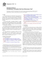
4.1.2.1 Standard Hole-Type Image quality indicators (IQIs)
shall dimensionally conform to the requirements of Fig. 1.
4.1.3 Modified Hole-Type IQI:
4.1.3.1 The rectangular IQI may be modified in length and
width as necessary for special applications, provided the hole
size(s) and IQI thickness conform to Fig. 1 or 4.1.4, as
applicable.
1
This practice is under the jurisdiction of ASTM Committee E07 on Nondestructive Testing and is the direct responsibility of Subcommittee E07.01 on
Radiology (X and Gamma) Method.
Current edition approved Dec. 15, 2011. Published January 2012. Originally
approved in 1984. Last previous edition approved in 2005 as E1025 - 05. DOI:
10.1520/E1025-11.
2
For ASME Boiler and Pressure Vessel Code applications see related Practice
SE-1025 in Section II of that Code.
3
For referenced ASTM standards, visit the ASTM website, www.astm.org, or
contact ASTM Customer Service at For Annual Book of ASTM
Standards volume information, refer to the standard’s Document Summary page on
the ASTM website.
4
Available from Standardization Documents Order Desk, DODSSP, Bldg. 4,
Section D, 700 Robbins Ave., Philadelphia, PA 19111-5098, http://
dodssp.daps.dla.mil.
*A Summary of Changes section appears at the end of this standard
Copyright © ASTM International, 100 Barr Harbor Drive, PO Box C700, West Conshohocken, PA 19428-2959. United States
1
E1025 − 11
NOTE
NOTE
NOTE
NOTE
NOTE
1—Tolerances for IQI thickness and hole diameter.
2—Tolerances for True T-hole Diameter IQI thickness and hole diameter shall be 610 %.
3—XX identification number equals T in .001 inches.
4—IQIs No. 1 through 9 for Standard Hole Type IQI’s (4.1.2) are not 1T, 2T, and 4T.
5—Holes shall be true and normal to the IQI. Do not chamfer.
Identification
Number T
(Note 3)
1–4
5–20
21–50
51–160
Over 160
A in. (mm)
1.500 (38.1)
±0.015 (0.38)
1.500 (38.1)
±0.015 (0.38)
1.500 (38.1)
±0.015 (0.38)
2.250 (57.15)
±0.030 (0.762)
1.330T
±0.005 (0.127)
B in. (mm)
0.750 (19.05)
±0.015 (0.38)
0.750 (19.05)
±0.015 (0.38)
0.750 (19.05)
±0.015 (0.38)
1.375 (34.93)
±0.030 (0.762)
0.830T
±0.005 (0.127)
C in. (mm)
0.438 (11.13)
±0.015 (0.38)
0.438 (11.13)
±0.015 (0.38)
0.438 (11.13)
±0.015 (0.38)
0.750 (19.05)
±0.030 (0.762)
...
D in. (mm)
0.250 (6.35)
±0.015 (0.38)
0.250 (6.35)
±0.015 (0.38)
0.250 (6.35)
±0.015 (0.38)
0.375 (9.53)
±0.030 (0.762)
...
FIG. 1 IQI Design
2
E in. (mm)
0.500 (12.7)
±0.015 (0.38)
0.500 (12.7)
±0.015 (0.38)
0.500 (12.7)
±0.015 (0.38)
1.000 (25.4)
±0.030 (0.762)
...
F in. (mm)
0.250 (6.35)
±0.030 (0.76)
0.250 (6.35)
±0.030 (0.76)
0.250 (6.35)
±0.030 (0.76)
0.375 (9.53)
±0.030 (0.762)
...
Tolerances (Note 2)
±10%
±0.0005 (0.127)
±0.0025 (0.635)
±0.005 (0.127)
±0.010 (0.254)
E1025 − 11
4.1.3.2 The IQI’s shall be identified as specified in 4.1.5 to
4.1.5.2, as applicable, except that the identification numbers
may be placed adjacent to the IQI if placement on the IQI is
impractical.
4.1.3.3 When modified IQI’s are used, details of the modification shall be documented in the records accompanying the
examination results.
4.1.4 True T-hole Diameter IQI:
4.1.4.1 It may be desirable for non-film applications to use
true T-hole diameter IQI’s for numbers 1 through 9.
4.1.4.2 Hole sizes for true T-hole diameter IQI’s may be
made by using laser or an electric discharge machining (EDM)
process and shall be within 610 % of 1T, 2T and 4T (See Fig.
1, Note 3 for T)
4.1.4.3 When true T-hole-diameter IQI’s are used, details of
the modifications shall be documented in the records accompanying the examination results.
4.1.5 Both the rectangular and the circular IQIs shall be
identified with number(s) made of lead or a material of similar
radiation opacity. The number shall be bonded to the rectangular IQI’s and shall be placed adjacent to circular IQI’s to
provide identification of the IQI on the image. The identification numbers shall indicate the thickness of the IQI in
thousandths of an inch, that is, a number 10 IQI is 0.010 in.
thick, a number 100 IQI is 0.100 in. thick, etc. Additional
identification requirements are provided in 7.2.
4.1.5.1 Alternative Identification Method—It may be desirable for non-film applications to eliminate the lead number
identifiers and replace them with either material addition or
material removal methods as stated below:
(1) Material Addition Method—Numbers may be made of
the same material as that of the IQI and of sufficient thickness
to be clearly discernable within the radiologic image.
(2) Material Removal Method—Numbers may be cut into
the IQI in such a manner as to be clearly discernable in the
radiologic image. Processes such as laser etching, chemical
etching, precision stamping, etc., may be used to create the
numbers within the IQI.
4.1.5.2 Alloy-group identification shall be in accordance
with 7.2. Rectangular IQI’s shall be notched as shown in Fig.
2, except the corner notch for Group 001 is at a 45 degree
angle. Round IQI’s shall be vibrotooled or etched as shown in
Fig. 3.
4.1.5.3 True T-hole diameter IQI identification numbers
shall be rotated 90° as compared to Standard Hole Type IQIs.
See Fig. 4.
NOTCH TOLERANCES
Width +15°
−0°
(A) Depth +1⁄16 in. (1.588mm)
−1⁄32 in. (0.794 mm)
FIG. 2 Rectangular IQI Notch Identification and Material Grouping
5. IQI Procurement
5.1 When selecting IQI’s for procurement, the following
factors should be considered:
5.1.1 Determine the alloy group(s) of the material to be
examined.
5.1.2 Determine the thickness or thickness range of the
material(s) to be examined.
5.1.3 Determine the Image Quality Level requirements as
described in Section 6 and Table 1.
5.1.4 Select the applicable IQI’s that represent the required
IQI thickness and alloy(s).
NOTE 1—This practice does not recommend or suggest specific IQI sets
to be procured. Section 5 is an aid in selecting IQI’s based on specific
needs.
6. Image Quality Levels
6.1 Image quality levels are designated by a two part
expression; X-YT. The first part of the expression, X, refers to
the IQI thickness expressed as a percentage of the specimen
thickness. The second part of the expression, YT, refers to the
diameter of the required hole and is expressed as a multiple of
3
E1025 − 11
TABLE 1 Typical Image Quality Levels
Standard Image Quality Levels
Minimum
Image Quality
Perceptible Equivalent IQI
IQI Thickness
Levels
Hole
Sensitivity, %A
Diameter
1⁄50 (2 %) of Specimen Thickness
2-1T
1T
1.4
2T
2.0
2-2TB
2-4T
4T
2.8
Special Image Quality Levels
1⁄100 (1 %) of Specimen Thickness
1-1T
1T
0.7
1-2T
2T
1
1⁄25 (4 %) of Specimen Thickness
2T
4
4-2T
FIG. 3 Circular IQI Identification
A
Equivalent IQI sensitivity is that thickness of the IQI, expressed as a percentage
of the part thickness, in which the 2T hole would be visible under the same
conditions.
B
For Level 2-2T Radiologic—The 2T hole in an IQI, 1⁄50 (2 %) of the specimen
thickness, is visible.
from this standard; however, Practice E747 (see Table 4)
contains provisions whereby wire sizes equivalent to corresponding 1T, 2T and 4T holes for various plaque thicknesses
are provided. Appendix X1 of Practice E747 also provides
methods for determining equivalencies between wire and hole
type IQI’s. This is not an alternative IQI provision for the
originally specified IQI requirements of this practice, but may
be useful for establishing technical image equivalency on a
case basis need with specific customer approvals.
FIG. 4 True T-hole Diameter Type IQI Identification Orientation
the IQI thickness, T (for example, the image quality level 2-2T
means that the IQI thickness, T, is no more than 2 % of the
specimen thickness and that the diameter of the required IQI
hole is 2 × T).
6.6 Test Methods E746 and E1735 provide additional tools
for determining relative image quality response of industrial
radiological systems when exposed to energy levels described
within those test methods. Both of these test methods use the
“equivalent penetrameter sensitivity” (EPS) concept to provide
statistical image quality information that allows the imaging
system or other exposure components to be assessed on a
relative basis. These test methods are not alternative IQI
provisions for the originally specified IQI requirements of this
practice, but may be useful on a case basis with specific
customer approvals, for establishing technical image equivalency of certain aspects of the radiological imaging process.
NOTE 2—Standard Hole Type Image Quality Indicators (IQI’s) less than
number 10 have hole sizes 0.010, 0.020, and 0.040 in. diameter regardless
of the IQI thickness. Therefore, Standard Hole Type IQI’s less than
number 10 do not represent the quality levels specified in 6.1 and Table 1.
The equivalent IQI sensitivity (EPS) can be calculated using the equation
in Appendix X1.
6.2 Typical image quality level designations are shown in
Table 1. The level of inspection specified should be based on
service requirements of the product. Care should be taken in
specifying True T-hole Diameter Type IQI’s (4.1.4) and/or
image quality levels 2-1T, 1-1T, and 1-2T by first determining
that these levels can be maintained in production.
7. Material Groups
6.3 In specifying image quality levels, the contract, purchase order, product specification, or drawing should state the
proper two-part expression and clearly indicate the thickness of
the material to which the level refers. In place of a designated
two–part expression, the IQI number and minimum discernible
hole size shall be specified.
7.1 General:
7.1.1 Materials have been designated in nine groups based
on their radiation absorption characteristics: Group 001 for
non-metals. Groups 03, 02, and 01 for light metals and Groups
1 through 5 for heavy metals.
7.1.2 The non-metals group, typically in the form of fiberreinforced phenolic resin, are identified as 001 since these
materials have the least radiation absorption of all the material
groups.
7.1.3 The light metal groups, magnesium (Mg), aluminum
(A1), and titanium (Ti) are identified 03, 02, and 01 respectively for their predominant alloying constituent. The materials
are listed in order of increasing radiation absorption.
7.1.4 The heavy metal groups, steel, copper base, nickel
base, and kindred alloys are identified 1 through 5. The
materials increase in radiation absorption with increasing
numerical designation.
6.4 Appendix X1 of this practice provides a method for
determining equivalent IQI sensitivity (EPS) in percent. Under
certain conditions (as described within the purchaser-supplier
agreement), EPS may be useful in relating a discernible hole
size of the IQI thickness with the section thickness radiographed for establishing an overall technical image quality
equivalency. This is not an alternative IQI provision for the
originally specified IQI requirement of this practice, but may
be a useful tool for establishing technical image equivalency on
a case basis need with specific customer approvals.
6.5 Practice E747 contains provisions for wire IQI’s that use
varying length and diameter wires to effect image quality
requirements. The requirements of Practice E747 are different
NOTE 3—The metals groups were established experimentally at 180 kV
on 3⁄4-in. (19-mm) thick specimens. They apply from 125 kV to the
4
E1025 − 11
7.3.6.1 Image quality indicators (IQI’s) shall be made of
aluminum bronze (Specification B150/B150M).
7.3.6.2 Use on all aluminum bronzes and all nickelaluminum bronzes.
7.3.7 Materials Group 3:
7.3.7.1 Image quality indicators (IQI’s) shall be made of
nickel-chromium-iron alloy (UNS No. NO6600) (Inconel).6
(Specification B166.)
7.3.7.2 Use on nickel-chromium-iron alloy and 18 %
nickel-maraging steel.
7.3.8 Materials Group 4:
7.3.8.1 Image quality indicators (IQI’s) shall be made of 70
to 30 nickel-copper alloy (Monel)7 (Specification B164) or
equivalent.
7.3.8.2 Use on nickel, copper, all nickel-copper series, or
copper-nickel series of alloys, and all brasses (copper-zinc
alloys). Group 4 IQI’s may be used on the leaded brasses, since
leaded brass increases in attenuation with increase in lead
content. This would be equivalent to using a lower group IQI.
7.3.9 Materials Group 5:
7.3.9.1 Image quality indicators (IQI’s) shall be made of
phosphor bronze (Specification B139/B139M).
7.3.9.2 Use on bronzes including gun-metal and valve
bronze, leaded-tin bronze of higher lead content than valve
bronze. Group 5 IQI’s may be used on bronze of higher lead
content since leaded bronze increases in attenuation with
increase in lead content. This would be equivalent to using a
lower group IQI.
multivolt range. The non-metal group was established experimentally at a
range of 15 to 60 kV on 0.100-in to 0.250-in (2.54-mm to 6.35-mm) thick
specimens using MIL-I-24768 thermosetting plastic laminated insulation
materials type FBE and FBG.
7.1.5 Common trade names or alloy designations have been
used for clarification of the pertinent materials.
7.1.6 The materials from which the IQI for the group are to
be made are designated in each case, and these IQI’s are
applicable for all materials listed in that group. In addition, any
group IQI may be used for any material with a higher group
number, provided the applicable quality level is maintained.
7.2 Identification System:
7.2.1 A notching system has been designated for the nine
materials groups of IQI’s and is shown in Fig. 2 for rectangular
IQI’s.
7.2.2 For circular IQI’s, a group designation shall be vibrotooled or etched on the IQI to identify it by using the letter “G”
followed by the group number, for example, G4 for a Group 4
IQI. For identification of the group on the image, corresponding lead characters shall be placed adjacent to the circular IQI,
just as is done with the lead numbers identifying the thickness.
An identification example is shown in Fig. 3.
7.3 Materials Groups:
7.3.1 Materials Group 001:
7.3.1.1 Image quality indicators (IQI’s) may be made from
phenolic resin laminate materials specified in MIL-I-24768, or
any of the materials listed in Practice E2662.
7.3.1.2 Use on polymer matrix composite materials or other
low density non-metal materials at low energies, typically
below 50 kV.
7.3.2 Materials Group 03:
7.3.2.1 Image quality indicators (IQI’s) shall be made of
magnesium or magnesium shall be the predominant alloying
constituent.
7.3.2.2 Use on all alloys of which magnesium is the
predominant alloying constituent.
7.3.3 Materials Group 02:
7.3.3.1 Image quality indicators (IQI’s) shall be made of
aluminum or aluminum shall be the predominant alloying
constituent.
7.3.3.2 Use on all alloys of which aluminum is the predominant alloying constituent.
7.3.4 Materials Group 01:
7.3.4.1 Image quality indicators (IQI’s) shall be made of
titanium or titanium shall be the predominant alloying constituent.
7.3.4.2 Use on all alloys of which titanium is the predominant alloying constituent.
7.3.5 Materials Group 1:
7.3.5.1 Image quality indicators (IQI’s) shall be made of
carbon steel or Type 300 series stainless steel.
7.3.5.2 Use on all carbon steel, all low-alloy steels, all
stainless steels, manganese-nickel-aluminum bronze (Superston).5
7.3.6 Materials Group 2:
5
NOTE 4—In developing the nine listed materials groups, a number of
other trade names or other nominal alloy designations were evaluated. For
the purpose of making this practice as useful as possible, these materials
are listed and categorized, by group, as follows:
(1) Group 2—Haynes Alloy IN-100.8
(2) Group 3—Haynes Alloy No. 713C, Hastelloy D,9 G.E. Alloy SEL,
Haynes Stellite Alloy No. 21,9 GMR-235 Alloy, Haynes Alloy No. 93,
Inconel X,6 Inconel 718, and Haynes Stellite Alloy NO. S-816.
(3) Group 4—Hastelloy Alloy F, Hastelloy Alloy X, and Multimeter Alloy
Rene 41.
(4) Group 5—Alloys in order of increasing attenuation: Hastelloy Alloy B,
Hastelloy Alloy C, Haynes Stellite Alloy No. 31, Thetaloy, Haynes Stellite
No. 3, Haynes Alloy No. 25. IQIs of any of these materials are considered
applicable for the materials that follow it.
(5) Group 001—Garolite
NOTE 5—The committee formulating these recommendations, recommended other materials may be added to the materials groups listed as the
need arises or as more information is gained, or that additional materials
groups may be added.
7.4 Radiologically Similar IQI Materials:
7.4.1 For materials not herein covered, IQI’s of radiographically similar materials may be used when the following
requirements are met. Two blocks of equal thickness, one of
the material to be examined (production material) and one of
the IQI material, shall be radiographed on one film by one
6
Inconel is a registered trademark of The International Nickel Co., Inc.,
Huntington, WV 25720.
7
Monel is a registered trademark of The International Nickel Co., Inc.,
Huntington, WV 25720.
8
All Haynes alloys are registered trademarks of Union Carbide Corp., New
York, NY.
9
All Hastelloys and Haynes Stellite alloys are registered trademarks of Cabot
Corp., Boston, MA.
Superston is a registered trademark of Superston Corp., Jersey City, NJ.
5
E1025 − 11
8. IQI Certification
exposure at the lowest energy level to be used for production
radiography. Film density readings shall be between 2.0 and
4.0 for both materials. If the film density of the material to be
radiographed is within the range of 0 to +15 % of the IQI
material, the IQI material shall be considered radiographically
similar and may be used to fabricate IQI’s for examination of
the production material.
7.4.1.1 Radiological similarity tests may be performed with
non-film radiological systems, however, the minimum and
maximum pixel values for both materials shall be within the
range established for production examinations.
7.4.2 It shall always be permissible to use IQI’s of radiologically less dense material than the subject material being
examined.
8.1 Records shall be available that attest to the conformance
of the material type, grouping (notches), and dimensional
tolerances of the IQI’s specified by this practice.
9. Precision and Bias
9.1 Precision and Bias—No statement is made about the
precision or bias for indicating the quality of radiological
images since the results merely state whether there is conformance to the criteria for success specified in this practice.
10. Keywords
10.1 density; image quality level; IQI; radiologic; radiology; X-ray and gamma radiation
APPENDIX
(Nonmandatory Information)
X1. EQUIVALENT IQI (PENETRAMETER) SENSITIVITY (EPS)10
X1.1 To find the equivalent IQI sensitivity (percent), the
hole size (diameter in inches), of the IQI thickness (inches), for
a section thickness (inches), the following equation may be
used:
where:
α
= 100
X
Œ
α
X
T
H
=
=
=
=
equivalent IQI sensitivity, %,
section thickness to be examined, in.,
IQI Thickness, in., and
hole diameter, in.
TH
,
2
10
O’Connor, D. T., and Criscuolo, E. L., “The Quality of Radiographic
Inspection,” ASTM Bulletin, ASTM, Vol 213, 1956, p. 52.
SUMMARY OF CHANGES
Committee E07 has identified the location of selected changes to this standard since the last issue (E1025 - 05)
that may impact the use of this standard. (December 15, 2011)
(5) Section 7: Added non-metals materials Group 001 for low
energy applications and compliance for Practice E2662; Editorial clarifications; Reworded Section 7.4 for Radiographic
Similar Materials to clarify calculation.
(6) Section 9: Editorially changed “radiographs” to “radiological images.”
(7) Figure 1: Added metric units and notes to drawing; Updated
Notes Section; Updated Table to include metric units.
(8) Figure 2: Added drawing for notch detail for non-metals
group 001.
(9) Table 1: Spelling correction.
(10) Figure 4: New drawing to show IQI identification orientation for True T-hole Diameter IQIs.
(1) Section 2: Updated Reference Documents.
(2) Section 4: Defined the current IQI (with minimum hole
sizes per Fig 1) as a “Standard Hole Type IQI”; Added
“Modified Hole Type IQI” to allow for modifications in length
and width which are may be used for geometric magnification
applications where the entire IQI is required to be in the image;
Added “True T-hole Diameter IQI” for which may be used for
geometric magnification applications where true 2 % EPS is
desired; Added alternative identification method other than
lead numbers and to require True T-hole Diameter IQI identification numbers rotated 90 degrees.
(3) Section 5: Added 5.1.3 to consider Image Quality requirement for IQI procurement.
(4) Section 6: Editorial clarifications.
6
E1025 − 11
(11) Appendix X1: Editorial clarifications; Deleted Nomograph since the provided equation is more accurate.
ASTM International takes no position respecting the validity of any patent rights asserted in connection with any item mentioned
in this standard. Users of this standard are expressly advised that determination of the validity of any such patent rights, and the risk
of infringement of such rights, are entirely their own responsibility.
This standard is subject to revision at any time by the responsible technical committee and must be reviewed every five years and
if not revised, either reapproved or withdrawn. Your comments are invited either for revision of this standard or for additional standards
and should be addressed to ASTM International Headquarters. Your comments will receive careful consideration at a meeting of the
responsible technical committee, which you may attend. If you feel that your comments have not received a fair hearing you should
make your views known to the ASTM Committee on Standards, at the address shown below.
This standard is copyrighted by ASTM International, 100 Barr Harbor Drive, PO Box C700, West Conshohocken, PA 19428-2959,
United States. Individual reprints (single or multiple copies) of this standard may be obtained by contacting ASTM at the above
address or at 610-832-9585 (phone), 610-832-9555 (fax), or (e-mail); or through the ASTM website
(www.astm.org). Permission rights to photocopy the standard may also be secured from the Copyright Clearance Center, 222
Rosewood Drive, Danvers, MA 01923, Tel: (978) 646-2600; />
7