Astm e 1190 11
Bạn đang xem bản rút gọn của tài liệu. Xem và tải ngay bản đầy đủ của tài liệu tại đây (122.92 KB, 6 trang )
Designation: E1190 − 11
Standard Test Methods for
Strength of Power-Actuated Fasteners Installed in Structural
Members1
This standard is issued under the fixed designation E1190; the number immediately following the designation indicates the year of
original adoption or, in the case of revision, the year of last revision. A number in parentheses indicates the year of last reapproval. A
superscript epsilon (´) indicates an editorial change since the last revision or reapproval.
1. Scope
3. Terminology
1.1 These test methods describe procedures for determining
the static axial tensile and shear strengths of power-actuated
fasteners installed in structural members made of concrete,
concrete masonry, and steel.
3.1 Definitions of general terms may be found in Terminology E631.
3.2 Definitions of Terms Specific to This Standard:
3.2.1 displacement—movement of a fastener relative to the
structural member. In tensile tests, displacement is measured
along the axis of the fastener; in shear tests it is measured in the
direction of the applied load perpendicular to the axis of the
fastener.
1.2 These test methods are intended for use with fasteners
that are installed perpendicular to a plane surface of the
structural member.
1.3 Tests for combined tension and shear, fatigue, dynamic,
and torsional load resistance are not covered.
3.2.2 drive pin—a nail-like metal fastener designed to attach
one material to another.
1.4 The values stated in SI units are to be regarded as
standard. The values given in parentheses are mathematical
conversions to inch-pound units that are provided for information only and are not considered standard.
1.5 This standard does not purport to address all of the
safety concerns, if any, associated with its use. It is the
responsibility of the user of this standard to establish appropriate safety and health practices and determine the applicability of regulatory limitations prior to use. Specific hazard
statements are given in Section 6.
3.2.3 edge distance, c—the distance from the longitudinal
axis (center) of a fastener to the nearest edge of the structural
member in which it is installed.
3.2.4 embedment depth, hef—the distance from the surface
of the structural member to the installed end of the fastener
including its point, if any.
3.2.5 fastener spacing, s—the distance between the longitudinal axes of two fasteners in the same plane. Also, distance
between longitudinal axis of fastener and nearest edge of
test-system supports (see s in Fig. 1).
2. Referenced Documents
2.1 ASTM Standards:2
E4 Practices for Force Verification of Testing Machines
E575 Practice for Reporting Data from Structural Tests of
Building Constructions, Elements, Connections, and Assemblies
E631 Terminology of Building Constructions
2.2 ANSI Standards:3
ANSI A10.3 Safety Requirements for Powder-Actuated Fastening Systems
3.2.6 powder-actuated fastening system—a system that uses
explosive powder to embed the fastener in structural elements.
3.2.7 power-actuated fastening system—a system that uses
explosive powder, gas combustion, or compressed air or other
gas to embed the fastener in structural elements.
3.2.8 shear test—a test in which a force is applied perpendicularly to the axis of the fastener and parallel to the surface
of the structural member.
3.2.9 static load—a load or series of loads that are supported
by or are applied to a structure so gradually that forces caused
by change in momentum of the load and structural elements are
negligible and all parts of the system at any instant are
essentially in equilibrium.
1
These test methods are under the jurisdiction of ASTM Committee E06 on
Performance of Buildings and are the direct responsibility of Subcommittee E06.13
on Structural Performance of Connections in Building Construction.
Current edition approved Sept. 1, 2011. Published October 2011. Originally
approved in 1987. Last previous edition approved in 2007 as E1190 – 95 (2007).
DOI: 10.1520/E1190-11.
2
For referenced ASTM standards, visit the ASTM website, www.astm.org, or
contact ASTM Customer Service at For Annual Book of ASTM
Standards volume information, refer to the standard’s Document Summary page on
the ASTM website.
3
Available from American National Standards Institute (ANSI), 25 W. 43rd St.,
4th Floor, New York, NY 10036, .
3.2.10 structural member—an element of a structural system such as a beam, column, or truss.
3.2.11 tensile test—a test in which a fastener is loaded
axially in tension at a specified rate.
Copyright © ASTM International, 100 Barr Harbor Drive, PO Box C700, West Conshohocken, PA 19428-2959. United States
1
E1190 − 11
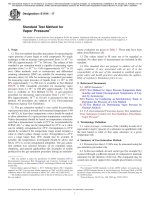
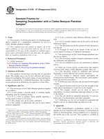
FIG. 1
Typical Static Tension Test Arrangement
fastener by means of a connector that will minimize the direct
transfer of bending forces through the connection. When
displacements are measured, dial gages or a linear variable
differential transformer (LVDT) shall be mounted in a manner
so as to ensure accurate displacement measurement.
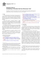
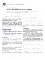
5.1.2 Shear Test:
5.1.2.1 A system suitable for applying shear forces is shown
in Fig. 2. for a single fastener specimen. The components of the
test fixture shall be of sufficient size and strength to prevent
yielding during application of the ultimate test load. The test
system support shall be of sufficient size to prevent local failure
of the structural member in the bearing contact area. When
displacements are measured, dial gages or a linear variable
differential transformer (LVDT) shall be mounted in a manner
so as to ensure accurate displacement measurement.
5.1.2.2 The thickness of the shear fixture in the immediate
vicinity of the test fastener shall be approximately equal to the
fastener shank diameter at the point of intersection of the
fastener and the base material unless otherwise specified. The
hole in the shear fixture designed to accommodate the fastener
shall have a diameter that is 0.5 6 0.1 mm (0.020 6 0.004 in.)
greater than that of the fastener shank diameter tested.
Alternatively, a shear fixture using a slot to accommodate the
fastener instead of a round hole shall be permitted. The loading
end of the slot shall have a width that is 0.5 6 0.1 mm
(0.020 6 0.004 in.) greater than that of the fastener shank
diameter tested. The non-loading end of the slot is permitted to
be larger than the fastener head or thread diameter. The initial
shape of the hole or the loading end of the slot in the shear
fixture shall correspond to that of the fastener shank cross
section and shall be maintained throughout all tests. For shear
fixtures using a slot to accommodate the fastener instead of a
3.2.12 threaded stud—a round metal-wire fastener, with a
pointed shank at one end and threads along the other end,
designed to be used as a removable fastening or in conjunction
with a threaded coupler.
4. Significance and Use
4.1 These test methods are intended to measure the anchoring capability and shear resistance of power-actuated fasteners
to provide information from which applicable design values are
to be derived for use in structural applications, such as in
members of concrete, concrete masonry, and steel.
5. Apparatus
5.1 Equipment—Any system suitable for applying tensile
and shear forces shall be used, provided the requirements for
rate of loading in 9.4 are met, and the instrumentation is
capable of measuring the forces to an accuracy within 6 2 %
of the applied force, when calibrated in accordance with
Practices E4. The device shall be of sufficient capacity to
prevent yielding of its various components and shall ensure
that the applied tensile forces remain parallel to the axes of the
fasteners and that the applied shear forces remain parallel to the
surface of the structural member during testing. Load cells
shall be used for laboratory testing. If pressure gages are used
for field testing, they shall be calibrated immediately prior to
use.
5.1.1 Tensile Test—A system suitable for applying tensile
forces is shown in Fig. 1 for a single fastener specimen. The
test system supports shall be of sufficient size to prevent failure
of the surrounding structural member. The loading rod shall be
of a size to develop the ultimate strength of the fastener
hardware with minimal elongation and shall be attached to the
2
E1190 − 11
FIG. 2
Typical Static Shear Test Arrangement
positioned to measure displacement in the direction of the
applied force. The displacement sensor shall be placed on the
structural member to allow the sensing element to be in direct
contact with the fastener or be attached directly to the fastener.
For tests on clusters of fasteners, the instrument shall lie in a
plane through the axis of the shear loading rod or plate. An
extension of the axis of the shear fixture shall pass through the
centroid of the cluster of fasteners.
hole, loading is to be applied parallel to the slot. Worn or
deformed holes or slots shall be repaired. When required, insert
sleeves shall be installed in the shear plate to meet these
requirements, provided they do not increase deformation of the
anchorage under load.
5.2 Optional Displacement Measurements— Displacement
or deformation measurements are not required to derive design
data for a given fastening system.
5.2.1 Tension Test (see Fig. 1)—Dial gages, having a smallest division of not more than 0.025 mm (0.001 in.), or any
suitable measurement devices or calibrated sensors of at least
comparable accuracy and sensitivity, such as an LVDT, shall be
used to measure displacement of the fastening system relative
to the structural member. The instruments shall be positioned
to measure the vertical movement of the fastener with respect
to points on the structural member, at a minimum distance of
40 mm (1.6 in.) from the center of the test fastener. The
instruments shall be mounted on the fastener specimen or
loading rod at a distance not more than 100 mm (4.0 in.) from
the structural member surface, in order to minimize extraneous
movements (hardware elongation) in the displacement measurements.
5.2.2 Tests of a Group of Fasteners— Only one set of
instruments is required for a group of fasteners tested as a
closely spaced cluster. The displacement to be used for the
evaluation of the findings is the average deformation indicated
by all instruments mounted symmetrically equidistant from the
center of the cluster.
5.2.3 Shear Test (see Fig. 2)—A single dial gage, having a
smallest division of not more than 0.025 mm (0.001 in.) or any
suitable measurement device, such as an LVDT, or calibrated
sensor of at least comparable accuracy and sensitivity shall be
used to measure the displacement of the fastening system
relative to the structural member. The instrument shall be
6. Hazards
6.1 Take precaution to ensure that people are not injured and
that test equipment, instrumentation, and the building, its
components, and its finish are not damaged prior to, during, or
after load application, by any unexpected release of potential
strain energy accumulated during testing.
6.2 All operators of powder-actuated tools used for the
installation of test specimens shall be licensed by the manufacturer. Operators shall comply with ANSI A10.3 requirements and local safety requirements.
7. Test Specimens
7.1 Fastening System—The fastening system shall be representative of the type and lot to be used in field construction
and shall include all accessory hardware normally required.
7.2 Fastener Installation—The fasteners shall be installed
using the manufacturer’s installation instructions and tools or,
where specific deviation is justified, in accordance with accepted field methods or to meet the requirements of the tests.
7.3 Fastener Placement—All fasteners (types, sizes, embedment depths) to be used in a given installation shall either be
tested individually or in groups of two or more at the intended
spacing. Fasteners shall be installed at distances equal to or
greater than those specified in Table 1 to preclude influences
3
E1190 − 11
TABLE 1 Fastener Spacing, s, and Edge Distance, c, to Preclude
Influences on Fastener Performance
Shank Diameter,
mm (in.)
Minimum Fastener
Spacing,
mm (in.)
Steel
Concrete
25 (1.0)
100 (4.0)
2.5 to 4.0
(0.100 to 0.156)
4.1 to 5.0
25 (1.0)
130 (5.1)
(0.157 to 0.199)
5.1 to 6.5
40 (1.6)
150 (5.9)
(0.200 to 0.250)
† The value in parenthesis was corrected editorially
TABLE 2 Number of Tests Required For Statistical Data
Coefficient of Variation, %
Up to 15
15 and greater
Minimum Edge Distance,
mm (in.)
Steel
12 (0.5)
Concrete
80 (3.2)†
12 (0.5)
90 (3.5)
25 (1.0)
100 (4.0)
Minimum Number of Tests Required
10
30
Alternatively, if the sample size is ten and the coefficient of
variation is 15 % or greater, the fastener capacity shall be based
on the lowest test value for the original ten tests instead of
increasing the sample size.
8.2 All installed fasteners shall be tested regardless of
fastener embedment, angle of installation, damage to the
structural member, or damage to the fastener. Fasteners that
cannot be tested, because they did not set at all, that is were not
installed properly, shall be reported as invalid data points.
Invalid data points shall not be included when determining the
average ultimate test values.
from adjacent fasteners or edges during testing. These distances are not to be considered minimum distances. Tests shall
be performed to determine minimum spacing and edge distances.
7.4 Structural Member—The structural member in which
the fastener is to be installed shall be representative of the
materials and configuration intended for field use. Concrete or
masonry structural members do not have to be reinforced with
steel (Note 1).
8.3 For developing minimum edge distances and fastener
spacings, the number of fasteners for each condition shall be at
least ten.
NOTE 1—The location and orientation of reinforcement embedded in
concrete and masonry members may influence fastener capacity. Their
influence shall be evaluated if reinforcement is used.
9.1 Positioning of Loading System:
9.1.1 Tension Test—Position the loading system over the
fastener, such as shown in Fig. 1, in such a way that the test
system supports are equidistant from the test fastener and
spaced sufficiently apart as not to influence the test findings.
The failure plane of the fastening system shall not interact with
the test system supports. Provide uniform contact between the
surface of the structural member and the test system supports.
Position and attach the loading rod so that the load is applied
through the center of a single fastener, as shown in Fig. 1, or
through the centroid of a cluster of fasteners. Whenever a
loading plate is required in the testing of a cluster of fasteners,
make every effort to provide uniform loading of the individual
fasteners of the cluster.
9.1.2 Shear Test—Position and fasten the structural member
as shown in Fig. 2 in such a way that the test surface of the
structural member is parallel to the shear plate and the long
axis of the shear rod. Place the shear fixture onto the structural
member and secure it in place with the appropriate nut or other
locking device used for the particular fastener to be tested. The
amount of force exerted on the shear plate by the nut or locking
device has a significant effect on the shear capacity of the
fastening system and shall be uniform for each series of tests
performed. The amount of force applied shall be in accordance
with that specified by the fastener manufacturer or, where
specific deviation is justified, in accordance with accepted field
methods.
9. Procedure
7.5 The concrete or masonry structural member thickness,
T, shall be sufficient to ensure that the installation and testing
of the fastener will not crack or cause any other failure of the
base material.
7.6 The length, L, and width, W, of concrete structural
members shall ensure that no shear breakout or tension failure
spall intersects either the outside edges of the structural
member or the bearing contact points of the test frame.
7.7 The edge distance, c, shall be as in Table 1 where the
reaction bridge in the shear test set-up shown in Fig. 2 provides
a minimum 150-mm (5.9-in.) clearance along the edge of the
concrete structural member and a minimum 50-mm (2.0-in.)
clearance along the edge of a steel structural member (not
shown). A shear reaction bridge is not required when concrete
edge distances exceed 150 mm or steel edge distances exceed
50 mm.
7.8 When testing fasteners installed in horizontal mortar
joints, the masonry wall shall be treated as a complete
structural member. The minimum edge distances and spacing
listed in Table 1 for concrete structural members do not apply
to masonry walls. Fasteners shall be installed in masonry walls
using the manufacturer’s installation instructions or in accordance with accepted field methods.
9.2 Mounting of Instruments (see 5.2):
9.2.1 Tension Test—Use dial gages, measurement devices,
or suitable sensors, as specified in 5.2.1, for each individual
fastener or cluster of fasteners. Mount the instruments on the
fastener or loading rod in accordance with the requirements of
5.2.1. Place the sensing elements of the instruments normal to
and in contact with a special bearing plate on the surface of the
structural member in such a way as to measure displacement in
the direction of the applied load. For clusters, use at least two
8. Number of Tests
8.1 Tensile or Shear Resistance—For determining the average tensile or shear resistance, perform at least the minimum
number of tests per condition specified in Table 2. Depending
on the purpose of the test, the number of tests shall be
increased. These tests shall be repeated for each variation in
fastener type, size, embedment depth, location, and for each
variation in the type or strength of structural member.
4
E1190 − 11
12. Report
instruments in any convenient arrangement consistent with the
requirements of 5.2.2.
9.2.2 Shear Test—Use a single instrument to measure shear
slip of either individual or clustered fasteners. Mount the
instrument on the structural member to allow the sensing
element to be attached directly to the fastener as previously
described, in such a way as to measure displacement in the
direction of the applied load.
12.1 The report on static tests shall include the applicable
information listed in Practice E575 and specifically the following:
12.1.1 Date of test and date of report,
12.1.2 Test sponsor and test agency,
12.1.3 Identification of fasteners tested: manufacturer,
model, type, material, finish, shape, dimensions, and other
pertinent information, such as power level of cartridges used to
install test specimens, cracks, and other defects,
12.1.4 Description of the fastening system tested and physical description of the structural members, including dimensions of the test section, and pretest curing, if any,
12.1.5 Detailed drawings or photographs of test specimens
before and after testing if not fully described otherwise,
12.1.6 Description of test equipment used and calibration
records,
12.1.7 Physical strength properties of the structural member
in which the fastener(s) is embedded, based on test data for
concrete cylinders, masonry units, or grout, obtained at time of
fastener tests,
12.1.8 Concrete mixture(s), including a complete description of the type and size of aggregate used in the concrete and
water-cement ratio, if applicable,
12.1.9 Mill certificates for structural steel members,
12.1.10 Description of the procedure and materials used to
install the fastening system,
12.1.11 Age, in days, of the structural member at time of
test,
12.1.12 Age, in hours or days, of fastening system since
installation, where applicable,
12.1.13 Moisture condition, at the time of test, of the
structural member in percent of oven-dry weight (Note 2),
where applicable,
12.1.14 Average depth, in millimetres (inches), of fastener
embedment,
12.1.15 Description of test method and loading procedure
used and actual rate of loading,
12.1.16 Number of replicate specimens tested,
12.1.17 Number of, and reason(s) for, test specimens not
tested,
12.1.18 Individual and mean maximum load values, in
newtons (or pounds-force), per embedded fastener (Pt or Ps, or
both) and standard deviations, where applicable,
12.1.19 Individual and mean slip values (optional) at ultimate and intermediate load values, in millimetres (inches), and
load versus displacement graphs (optional),
12.1.20 Photographs, sketches, or word descriptions of the
failure modes observed,
12.1.21 Summary of findings,
12.1.22 Relevant test limitations and recommendations, and
12.1.23 Listing of observers of tests and signatures of
responsible persons.
9.3 Load Application for a Given Period—If application of
a given load is required for a certain period, such as 24 h,
deformation readings shall be taken at the beginning, at
intervals during this period, and at the end of this period, to
allow the satisfactory plotting of a time-deformation curve for
the complete period.
9.4 Rate of Loading—Apply the rate of increment loading at
a constant rate of motion of the movable crosshead of the
testing machine or at a uniform rate of loading. Run the test
with the force being applied at a uniform rate so that the
ultimate strength of the fastener is reached in no less than 30 s.
10. Failure Analysis
10.1 Load at Failure—Determine the maximum test load for
each assembly tested to failure.
10.2 Concrete or Masonry Failure Modes— Failure occurs
by one or a combination of the following modes:
10.2.1 Brittle failure of the structural member in the form of
a shear cone.
10.2.2 Failure of the structural member by cracking that
radiates outward from the location of the fastening device,
resulting in pull-out of the fastener.
10.2.3 Failure of the bond between a fastener and the
structural member.
10.3 Fastener Failure Modes—Failure occurs by one or a
combination of the following modes:
10.3.1 Failure of the bond between a fastener and the
structural member (tension).
10.3.2 Ductile failure of the fastener (tension).
10.3.3 Shear failure of the fastener.
10.3.4 Bending failure of the fastener (shear).
10.4 The yielding or fracture of any component of the
fastening device including hardware accessories shall constitute failure.
11. Calculation
11.1 Maximum Load Data:
11.1.1 Determine the average of the maximum loads per
fastener as the arithmetic mean of all maximum loads for a
given test series where Pt = average ultimate load in a tension
test series, and Ps = average ultimate load in a shear test series.
11.1.2 In tests of clusters of fasteners, the average of the
maximum loads per test series is divided by the number of
fasteners per cluster in order to obtain the average of the
maximum loads per fastener.
11.1.3 Determine the standard deviation.
NOTE 2—The moisture content of the structural member at time of test
may be determined by several methods including drying of small samples
to constant mass or use of moisture meters.
5
E1190 − 11
13. Precision and Bias
13.1 Precision—No data are available on precision of these
test methods.
13.2 Bias—Data cannot be obtained on bias of these test
methods since no standard reference materials exist.
14. Keywords
14.1 concrete; drive pin; edge distance; failure modes;
fastener; masonry; powder-actuated; power-actuated; shear
test; spacing; structural member; tension test; threaded stud
ASTM International takes no position respecting the validity of any patent rights asserted in connection with any item mentioned
in this standard. Users of this standard are expressly advised that determination of the validity of any such patent rights, and the risk
of infringement of such rights, are entirely their own responsibility.
This standard is subject to revision at any time by the responsible technical committee and must be reviewed every five years and
if not revised, either reapproved or withdrawn. Your comments are invited either for revision of this standard or for additional standards
and should be addressed to ASTM International Headquarters. Your comments will receive careful consideration at a meeting of the
responsible technical committee, which you may attend. If you feel that your comments have not received a fair hearing you should
make your views known to the ASTM Committee on Standards, at the address shown below.
This standard is copyrighted by ASTM International, 100 Barr Harbor Drive, PO Box C700, West Conshohocken, PA 19428-2959,
United States. Individual reprints (single or multiple copies) of this standard may be obtained by contacting ASTM at the above
address or at 610-832-9585 (phone), 610-832-9555 (fax), or (e-mail); or through the ASTM website
(www.astm.org). Permission rights to photocopy the standard may also be secured from the ASTM website (www.astm.org/
COPYRIGHT/).
6