Indirect space vector control of matrix converter
Bạn đang xem bản rút gọn của tài liệu. Xem và tải ngay bản đầy đủ của tài liệu tại đây (823.5 KB, 6 trang )
Indirect Space Vector Control of Matrix Converter
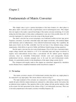
Michal Kabasta, VSB – Technical University Ostrava
Abstract
In this paper is presents a control strategy for
three-phase matrix converter, which is based on the
Space Vector Modulation technique (SVM). SVM
technique is utilized to calculate the duty cycles of
the active voltage vectors that must be applied in
each switching cycle period, in order to satisfy the
input and output requirements. SVM technique use
simpler algorithm if is compare with first
modulation technique proposed by Venturini. The
SVM technique allows us a direct understanding of
switching patterns and their characteristics from the
viewpoint of analysis and control. The validity of
the proposed method is proven from simulation and
the output voltage and the input current generated
by the model of converter are shown here.
1. Introduction
Many of industrial application require AC/AC
energy conversion and AC/AC converters. AC/AC
converters take electrical energy and changed it to
different ac system – waveforms with different
amplitude, different frequency and phase. We can
classify two main class of ac converters, first ist
indirect ac converters and second is direct energy
converters. In indirect energy converters are usually
two energy stage – rectifier, which convert input ac
energy to dc energy and then is here inverter for
changing dc energy back to ac energy with different
variables on output, if is compare with input ac
energy. These two stages of energy conversion Fig.
1. are decoupled and controlled independently and
average energy flow is equal. The difference between
the instantaneous input and output power must be
absorbed or delivered by an energy storage element
within converter. This energy storage element is a
capacitor or an inductor.
AC
DC
DC
AC
DC
LINK
(a)
AC
AC
(b)
Fig. 1. (a ) indirect AC/AC (b) di rect AC /A C conv erter
But if is use direct energy converter, then the
energy storage element is not needed Fig. 1. (b). In
direct energy converter are two main areas. First is
cycloconverter and the main function is change the
output frequency lower then input frequency. In this
topology is impossible to get higher output
frequency then frequency on input side. The desired
output waveforms are making by synthesizing it
from pieces of the input waveform. Second stream
is matrix converter (MC) and this is better then
cycloconverter for adjustable drive, because here is
not any limit on the output frequency, limitation is
only on output amplitude, which is smaller then
input amplitude Fig. 2. This limitation can be solving
using overmodulation technique.
0
0
0,4
-0,4
0,8
-0,8
1,2
-1,2
90
180
270
360
Input Voltage
Output Voltage
Fig. 2. I nput and outp ut wav eforms
Matrix converter replace two energy conversion
to only one energy conversion, because within
converter is not any energy storage element. MC
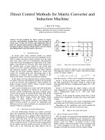
need special semiconductor switches. The matrix
converter requires a bidirectional switch, capable of
blocking voltage and conducting current in both
directions – the energy flow can get from source to
load and back. These bidirectional switches,
consisting of a pair of devices with turn-off
capability, are usually insulated gate bipolar
transistors (IGBTs), in either a common collector or
a common emitter back-to-back arrangement.
Usually, each IGBT has an anti-parallel diode Fig. 3.
Matrix converters contain an array Fig. 3. of bi-
directional semiconductor switches and this array
allows connection of all input lines to all output
lines.
441
X International PhD Workshop
OWD’2008, 18–21 October 2008
Fig. 3. Dir ec t ma trix conv erter and bidi rectional
switches
If the switches are arrangement as is shown on
Fig. 3. then the power flow in converter is able be
reverse. Thanks to absence of any energy storage
element, the instantaneous power on input must be
the same as the power on output side. Unfortunately
reactive power input does not have to equal the
reactive power output. In MC it is possible to the
control of phase angle between the voltages and
current at the input – the output phase angle can be
different from input phase. Another good think is
that the forms of waveforms at the two sides are
independent. So the input can be three-phase ac and
output dc, or both can be dc, or both can be ac.
From this case, the MC topology is good for
universal power conversion such as: AC/DC,
DC/AC, DC/DC, AC/AC without any change of
topology [5], [7].
2. Control of Matrix Converter
For many AC drive applications is good to use a
compact voltage source converter to provide
sinusoidal output voltages with varying amplitude
and frequency. But if is use indirect power converter,
then inside is usually large capacitor or inductor and
this is not good for size of converter. In MC is not
any DC-link so the MC can be smaller then common
indirect converter. Of course, that MC need good
control strategy, because in MC is not any natural
path for commutation. The control of MC is divide
to the two section. First section is direct control of
matrix converter, second is indirect control of matrix
converter.
2.1 Limitation of Control for MC
For explanation of limitation of control is use
Fig. 4. where is simplified 3ph 3ph. matrix convertor
topology.
Matrix converter consists nine bidirectional
switches and each output phase is done from set of
three switch which are connected to three input
phases.
Fig. 4. Simpli fi ed topo logy of 3ph. -3ph. matrix
converter
In this combination is possible to connect any of
input phase a ,b ,c to any output phase A, B, C at any
instant. If MC is supplied as the voltage sources, the
input phase must not be shorted at any time and if
inductive load is on output side, then the output
phases can not be open. This condition is shown in
Fig.5. for set of switch on output phase A.
(a)
(b)
Fig. 5. Swit ching restricti on (a) sho rt circui t on input
phases (b) op en circui t on output p hases
Mathematically the conditions are below [1], [2]:
If the switch function of a switch S
ij
in Fig. 4. is
defined as
1)(
=
tS
ij
,S
ij
closed
{
}
cbai
,,
∈
,
{
}
CBAj
,,
∈
0, S
ij
open
The constraints can be expressed as:
1
=++
cjbjaj
SSS
{
}
CBAj
,,
∈
(1)
The control strategy based on this two basic
rules, the number of legal switch states is 27. Each
switch state can be described by three letter code.
The code describe which output phase is connected
to which input side. For example, the state of switch
with name aba show, that output phase A is
connected to input phase a, output phase B is
connected to input phase b and output phase C is
connected to input phase a.
3 Direct Control of Matrix Converter
In this case, the output waveforms are made from
small pieces from input waveforms. This is done
selecting catch of the input phases in sequence for
defined period of time. The sequence for each
442
phases is the same [3]. How this waveform looks is
shown in Fig. 6. The output voltages have inside
some segments from three input voltages. Input
current includes segments from three output
currents.
Fig. 6 One o utput p hase
The idea of direct control of MC is based on
mathematical expression (2,3), which describe the
conditions between output and input side. With help
of these equations is defined the duty cycle for each
switch.
For output voltage:
=
)(
)(
)(
)()()(
)()()(
)()()(
)(
)(
)(
tv
tv
tv
tmtmtm
tmtmtm
tmtmtm
tv
tv
tv
c
b
a
cCbCaC
cBbBaB
cAbAaA
C
B
A
(2)For input current:
=
)(
)(
)(
)()()(
)()()(
)()()(
)(
)(
)(
ti
ti
ti
tmtmtm
tmtmtm
tmtmtm
ti
ti
ti
C
B
A
cCcBcA
bCbBbA
aCaBaA
c
b
a
(3)
Where
seq
aA
aA
T
t
tm
=
)(
a
aA
t
is switch connected
to the input phase a and output phase A . This
equation can be represented in short form too:
[
]
[
]
[
]
[ ] [ ] [ ]
)()()(
)()()(
titMti
tvtMtv
O
T
I
IO
=
=
(4)
Where
[
]
)(
tM
is modulation matrix.
Simulation result for this control for matrix
converter will be show below.
4. Indirect Space Vector Control of
Matrix Converter
A principle of this control strategy is based on
virtual DC-link in matrix converter. This DC-link is
not physically present, but the switches are divide to
the virtual rectifier and virtual inverter Fig. 7. The
indirect space vector modulation is gaining as a
standard technique in the matrix converter
modulation [6], [4], [8].
M
a
b
c
S
1
S
7
V
DC
V
DC+
I
DC+
V
DC-
I
DC-
S
9
S
11
S
3
S
5
S
2
S
4
S
6
S
8
S
10
S
12
A
B
C
Virtual Rectifier
Virtual Inverter
Fig. 7. Virtu al DC-link
Indirect space vector modulation is equivalent
circuits combining current source rectifier and
voltage source inverter connected by DC-link.
Inverter stage has a standard 3ph voltage source
topology based on six switches S7-S12 and rectifier
stage based on switches S1-S6 with same topology.
This two circuit has provided platform for analyze
and derive several extends PWM strategies.
The basic idea of the indirect modulation
technique is to decouple the control of the input
current and the control of the output voltage. This is
done by splitting the transfer function T for the
matrix converter in (5) into the product of a rectifier
and an inverter transfer function.
R
I
T
∗
=
⋅
=
6
5
4
3
2
1
12
10
8
11
9
7
S
S
S
S
S
S
S
S
S
S
S
S
SSS
SSS
SSS
cCbCaC
cBbBaB
cAbAaA
(5)
where the matrix I is the inverter transfer
function and the matrix R is the rectifier transfer
function. This way to model the matrix converter
provides the basis to regard the matrix converter as a
back-to-back PWM converter without any DC-link
energy storage.
This means the well know space vector PWM
strategies for voltage source inverter (VSI) or PWM
rectifier can be applied to the matrix converter.
⋅
⋅
=
c
b
a
C
B
A
V
V
V
S
S
S
S
S
S
S
S
S
S
S
S
V
V
V
6
5
4
3
2
1
12
10
8
11
9
7
(6)
443
The above transfer matrix exhibits that the
output phases are compounded by the product and
sum of the input phases through inverter switches
S7-S12 and rectifier switches S1-S6.
⋅
⋅+⋅
⋅+⋅
⋅+⋅
⋅+⋅⋅+⋅
⋅+⋅⋅+⋅
⋅+⋅⋅+⋅
=
c
b
a
C
B
A
V
V
V
SSSS
SSSS
SSSS
SSSSSSSS
SSSSSSSS
SSSSSSSS
V
V
V
612511
61059
6857
412311212111
4103921019
48372817
(7)
The first row represents how output phase A is
built from the input phase a, b and c and this
mathematical expression can be interpreted again in
the graphical viewpoint. If the equivalent circuit is
seen from the inverter output phase A, two switches
S7 and S8 of phase A half bridge is directly
connected to input phases a, b and c through six
rectifier switches S1-S6. Fig. 8
.
. shows how the switch
set of equivalent circuit can be transformed into the
relevant switch set of the nine bidirectional switched
matrix converter in the case of phase A and gives an
basic idea that the duty cycles of the matrix
converter branch can be derived by multiplying the
duty cycles of the corresponding rectifier and
inverter switches in the equivalent circuit [4].
(a)
(b)
Fig. 8. Transfor mation from equiv alent circui t to phase
A in matrix c onverte r
Therefore the indirect modulation technique
enables well-known space vector PWM to be applied
for a rectifier as well as an inverter stage.
The switches of inverter can have only eight
allowed combinations, because the output must not
be short though three half bridge. This eight
combination can be divide into six active nonzero
output voltages vector V1 ~ V6 and two zero
output voltages vector V0 show in Fig. 9. .
The voltage space vector V1[100] indicates that
output phase VA is connected to positive rail VDC+
and the other phase VB, VC are connected to
negative rail VDC- and its vector magnitude is
calculated from
6
3
4
3
2
3
4
3
2
1
3
2
3
1
3
1
3
2
3
2
3
2
π
ππ
ππ
j
DC
j
DC
j
DCDC
j
C
j
BA
eV
eVeVV
eVeVVV
⋅=
=
⋅⋅−⋅⋅−⋅=
=
⋅+⋅+=
(8)
Fig. 9. Hexago n for inv erter voltag e
For virtual rectifier is allowed nine switching
combination to avoid a open circuit in rectifier. This
nine combination is divided into six active nonzero
input currents vectors I1 ~ I6 and three zero input
currents vector I0 Fig. 10 I1 [ab] indicates that
input phase a is connected to the positive rail of the
virtual DC-link VDC+ and input phase b is to the
negative rail VDC Its vector magnitude is
calculated from
6
3
4
3
2
3
4
3
2
1
3
2
0
3
2
3
2
π
ππ
ππ
j
DC
jj
DCDC
j
c
j
ba
eI
eeII
eIeIII
−
⋅=
=
⋅+⋅−=
=
⋅+⋅+=
(9)
Fig. 10. Hexag on for r ectifier c urrent
5. Simulation Result
The control of matrix converter is simulated
using the Matlab-Simulink package. Equation (2,3) is
used to obtain the elements of transfer matrix M(t).
The most important part of the simulation on direct
444
control for MC is the generation of the switching
functions of the bidirectional switches. These
functions are gate drive signals of the power
switches in the real converter. Simulation of indirect
space vector control of MC generate gate drive
signals on different way, first is checked the sector on
phases and then is choose the correspond vector
from table to get the right size of amplitude.
Different between direct and indirect control is, that
direct control is clearly mathematically based on
equation and indirect control is based on predefined
rules from table.
Parameters of simulation:
Source voltages 230V, 50Hz, load resistance
R=1,1Ω, load inductance L=0,005H
5.1. Simulation Result for Direct Control of
MC
Fig. 11. Input Voltages
Fig. 12. Input Currents
Fig. 13. Output Vol ta ges
Fig. 14. Output Curren ts
5.2. Simulation Result for Indirect Control
of MC
Fig. 15. Inpu t Voltages
Fig. 16. Inpu t Currents
Fig. 17. Output Voltag es
445
Fig. 18. Output Curren ts
6. Conclusion
The working principle of the MC controlled with
the direct transfer function approach and basic from
indirect space vector control has been presented.
Both control method was explained and used to get
the block diagram for the simulation. The model
reproduces a very good waveform on output side. In
addition, it can be observed that the MC can
generate output frequencies that are not restricted by
the source frequency – explanation on indirect
control, where is virtual DC-link, what is the case in
phase controlled cycloconverters.If is use drive
system with MC, then the the drive system is made
for capable of operating in all four-quadrant regions.
The simulation results agree with the theoretical
expectations, that the direct convert are able created
sinusoidal waveforms on output side, which is
necessary for good working condition of drive
systems.
Bibliography
[1] Altun H., Sunter. S.: Matrix Converter Induction
Motor Drive: Modeling, Simulation And Control,
Electrical Engineering 2003
[2] Rodriguez J., Silva E., Burgos R., Blaabjerk F.:
Modelling, Analysis and Simulation of Matrix
Converters, 2003
[3] Alesina A., Venturini M : Analysis and Design of
Optimum-Amplitude Nine-Switch Direct AC-AC
Converters, IEEE Transactions on Power
Electronics, Vol. 4 .No.1., 1989
[4] Osmančík L., Kabašta M.: Maticové měniče,
Elosys 2007, Trencin 2007
[5] Wheeler P., Rodriguez J., Clare J., Empringham L.,
Weinstein A : Matrix Converters: A Technology
Review, IEEE Trans. Ind. Electron., vol. 49,
N◦2, April 2002
[6] Wheeler P., Clare J.C., Empringham L.: A Vector
Controlled MCT Matrix Converter Induction
Motor Drive with Minimized Commutation
Times and Enhanced Waveform Quality, IEEE
Industrial Application Society Annual Meeting,
Pittsburgh 2002
[7] Clare J., Wheeler P.: Introduction to Matrix
Introduction to Matrix Converter Technology,
IEE Seminar 2003
[8] Kabašta M.: Metody řízení maticových měničů,
Elosys 2008, Trencin 2008
Authors:
Ing. Michal Kabašta
VŠB – Technical University
of Ostrava
17. listopadu 15
708 33 Ostrava – Poruba
Czech Republic
email:
446

![[Khiem] improvement of matrix converter drive reliability by online fault detection and a fault tolerant switching strategy IEEE trans](https://media.store123doc.com/images/document/14/y/ib/medium_ibr1399917315.jpg)