động cơ servo
Bạn đang xem bản rút gọn của tài liệu. Xem và tải ngay bản đầy đủ của tài liệu tại đây (7.51 MB, 224 trang )
VER 1.6
Introduction
iii
Introduction
Hello. Thank you for choosing LS Mecapion L7 Series.
This user manual describes how to use the product and what precautions to take.
Failure to comply with guidelines may cause injury or product damage. Be sure to read this
user manual before you use the product and follow all guidelines.
The contents of this manual are subject to change without prior notice depending on software
versions.
No reproduction of part or all of the contents of this manual in any form, by any means or for any
purpose, shall be permitted without the explicit written consent of LS Mecapion.
The patent, trademark, copyright and other intellectual property rights in this user manual are
reserved by LS Mecapion. No use for purposes other than those related to the product of LS
Mecapion shall be authorized.
Safety Precautions
iv
Safety Precautions
Safety precautions are categorized as either Danger or Caution, depending on the
seriousness of the precaution.
Precautions
Definition
Danger
Failure to comply with guidelines may cause death or serious injury.
Caution
Failure to comply with guidelines may cause injury or property damage.
Certain conditions that are listed as Caution may also result in serious injury .
Electric Shock Precautions
Danger
Before wiring or inspection tasks, turn off the power. Wait 15 minutes until the charge lamp
goes off, and then check the voltage.
Be sure to ground both the servo drive and the servo motor.
Only specifically trained professional engineers are permitted to perform wiring tasks.
Perform wiring tasks after you install both the servo drive and the servo motor.
Do not operate the device with wet hands.
Do not open the servo drive cover while in operation.
Do not operate the device with the servo drive cover removed.
Even if the power is off, do not remove the servo drive cover.
Fire Prevention Precautions
Caution
Install the servo drive, the servo motor, and the regenerative resistance on non-combustible
material.
In case of servo drive malfunction, disconnect the input power.
Safety Precautions
v
Installation Precautions
Store and use the product in an environment as follows:
Environment
Conditions
Servo Drive
Servo Motor
Usage temp.
0 ~ 50 ℃
0 ~ 40 ℃
Storage temp.
-20 ~ 65 ℃
-20 ~ 60 ℃
Usage
humidity
Below 90% RH (non-condensing)
Below 80% RH
Storage
humidity
Below 90% RH
Altitude
Below 1000 m
Spacing
When installing 1 unit:
More than 40 mm space at the top and
bottom of the control panel
More than 10 mm space at the left and
right sides of the control panel
When installing 2 or more units:
More than 100 mm space at the top of
the control panel
More than 40 mm space at the bottom
of the control panel
More than 30 mm space at the left and
right sides of the control panel
More than 2 mm between units
Refer to "2.2.2 Installation Inside the
Control Panel."
Others
Install in a location free from iron, corrosive gas, and combustible gas.
Install in a location free from vibration or shock.
Caution
Make sure that the installation orientation is correct.
Do not drop the product or expose it to excessive shock.
Install in a location that is free from water, corrosive gas, combustible gas, or flammable
material.
Install in a location that can support the weight of the product.
Do not stand on the product or place heavy objects on top of it.
Be sure to maintain the specified spacing when you install the servo drive.
Be sure not to get conductive or flammable debris inside either the servo drive or the servo
motor.
Firmly fix the servo motor onto the machine.
Be sure to install a servo motor with a gearbox in the specified direction.
Do not touch the rotating unit of the servo motor while you operate the machine.
Do not apply excessive shock when you connect a coupling to the servo motor shaft.
Do not place a load on the servo motor shaft that is heavier than specified.
Safety Precautions
vi
Wiring Precautions
Caution
Be sure to use AC 200-230 V for the input power of the servo drive.
Be sure to connect the servo drive ground terminal.
Do not connect commercial power directly to the servo motor.
Do not connect commercial power directly to the U, V, W output terminal of the servo drive.
Directly connect U, V, W output terminals of the servo drive and U, V, W input terminals of the
servo motor, but do not install a magnetic contactor between the wiring.
Be sure to use a pressurized terminal with an insulation tube when you connect the power
terminal for the servo drive.
When wiring, be sure to separate the U, V, and W cables for the servo motor power and
encoder cable.
Be sure to use robotic cable if the motor requires movement.
Before you perform power line wiring, turn off the input power of the servo drive, and then wait
until the charge lamp goes off completely.
Be sure to use shielded twisted-pair wire for the pulse command signal (PF+, PF-, PR+, PR-),
speed command signal (SPDCOM), and torque command signal (TRQCOM).
Precautions for Initial Operation
Caution
Check the input voltage (AC 200-230 V) and power unit wiring before you turn on the power.
The servo must be in the OFF mode when you turn on the power.
Before you turn on the power, check the motor's ID and the encoder pulse for L7 □A □□□A.
Set the motor ID ([P0-00]) and the encoder pulse ([P0-02]) for L7 □A □□□A first after you
turn on the power.
After you complete the above settings, set the drive mode for the servo drive that is connected
to the upper level controller to [P0-03].
Refer to Chapter 1.2 "System Configuration" to perform CN1 wiring for the servo drive
according to each drive mode.
You can check the ON/OFF state for each input terminal of CN1 at [St-14].
Precautions for Handling and Operation
Caution
Check and adjust each parameter before operation.
Do not touch the rotating unit of the motor during operation.
Do not touch the heat sink during operation.
Be sure to attach or remove the CN1 and CN2 connectors when the power is off.
Extreme change of parameters may cause system instability.
Safety Precautions
vii
Precautions for Use
Caution
Install an emergency stop circuit on the outside to immediately stop operation if necessary.
Reset the alarm when the servo is off. Be warned that the system restarts immediately if the
alarm is reset while the servo is on.
Minimize electromagnetic interference by using a noise filter or DC reactor. Otherwise, adjacent
electrical devices may malfunction because of the interference.
Use only the specified combinations of servo drive and servo motor.
The electric brake on the servo motor keeps the mortor at a standstill. Do not use it for ordinary
braking.
The electric brake may not function properly depending on the brake lifespan and mechanical
structure (for example, if the ball screw and servo motor are combined via the timing belt).
Install an emergency stop device to ensure mechanical safety.
Malfunction Precautions
Caution
For potentially dangerous situations that may occur during emergency stop or device
malfunction, use a servo motor with an electric brake, or separately install a brake system on
the outside.
In case of an alarm, solve the source of the problem. After you solve the problem and ensure
safety, deactivate the alarm and start operation again.
Do not get close to the machine until the problem is solved.
Precautions for Repair/Inspection
Caution
Before performing servicing tasks, turn off the power. Wait 15 minutes until the charge lamp
goes off, and then check the voltage. Voltage may remain in the condenser even after you turn
off power and may cause an electric shock.
Only authorized personnel are permitted to perform repair, inspection or replacement of parts.
Do not modify the product.
General Precautions
Caution
This user manual is subject to change upon product modification or standards changes. In case
of such changes, the user manual will be issued with a new product number.
Product Application
Caution
This product is not designed or manufactured for machines or systems that are used in
situations related to human life.
This product is manufactured under strict quality control. However, be sure to install safety
devices when applying the product to a facility where a malfunction in the product might cause
a major accident or significant loss.
Safety Precautions
viii
EEPROM Lifespan
Caution
EEPROM is rewritable up to 1 million times for the purpose of, among others, recording
parameter settings. The servo drive may malfunction depending on the lifespan of EEPROM
when the total counts of the following tasks exceed 1 million.
EEPROM recording as a result of parameter changes
EEPROM recording as a result of alarm trigger
Table of Contents
ix
Table of Contents
Introduction iii
Safety Precautions iv
Table of Contents ix
1. Product Components and Signals 1-1
1.1 Product Components 1-1
1.1.1 Product Verification 1-1
1.1.2 Part Names 1-3
1.2 System Configuration 1-7
1.2.1 Overview 1-7
1.2.2 Wiring Diagram of the Entire CN1 Connector 1-9
1.2.3 Example of Position Operation Mode Wiring 1-10
1.2.4 Example of Speed Operation Mode Wiring 1-11
1.2.5 Example of Torque Operation Mode Wiring 1-12
1.2.6 Examples of Speed / Position Operation Mode Wiring 1-13
1.2.7 Example of Speed/Torque Operation Mode Wiring 1-14
1.2.8 Example of Position/Torque Operation Mode Wiring 1-15
1.3 Signals 1-16
1.3.1 Digital Input Contact Signal 1-16
1.3.2 Analog Input Contact Signal 1-17
1.3.3 Digital Output Contact Signal 1-17
1.3.4 Monitor Output Signal and Output Power 1-18
1.3.5 Pulse Train Input Signal 1-18
1.3.6 Encoder Output Signal 1-19
2. Installation 2-1
2.1 Servo Motor 2-1
2.1.1 Usage Environment 2-1
2.1.2 Prevention of Excessive Shock 2-1
2.1.3 Motor Connection 2-1
2.1.4 Load Device Connection 2-2
2.1.5 Cable Installation 2-2
2.2 Servo Drive 2-3
2.2.1 Usage Environment 2-3
2.2.2 Installation Inside the Control Panel 2-4
2.2.3 Power Wiring 2-5
3. Wiring Method 3-1
3.1 Internal Block Diagram 3-1
3.1.1 L7 Drive Block Diagram [L7SA001□ - L7SA004□] 3-1
3.1.2 L7 Drive Block Diagram [L7SA008□ - L7SA035□] 3-2
3.2 Power Wiring 3-3
3.2.1 L7 Drive Wiring Diagram [L7SA001□ - L7SA035□] 3-3
3.2.2 Dimensions for Power Circuit Electrical Parts 3-4
3.3 Timing Diagram 3-5
3.3.1 Timing Diagram During Power Input 3-5
Table of Contents
x
3.3.2 Timing Diagram at the Time of Alarm Trigger 3-6
3.4 Control Signal Wiring 3-7
3.4.1 Contact Input Signal 3-7
3.4.2 Contact Output Signal 3-8
3.4.3 Analog Input/Output Signals 3-9
3.4.4 Pulse Train Input Signal 3-10
3.4.5 Encoder Output Signal 3-11
3.5 Quadrature Encoder Signaling Unit (CN2) Wiring 3-12
3.5.1 APCS-EAS Cable 3-12
3.5.2 APCS-EBS Cable 3-12
3.6 Serial Encoder Signaling Unit (CN2) Wiring 3-13
3.6.1 APCS-ECS Cable 3-13
3.7 Transmission of Absolute Encoder Data 3-15
3.7.1 Transmission of Absolute Encoder Data 3-15
4. Parameters 4-1
4.1 How to Use the Loader 4-1
4.1.1 Name and Function of Each Part 4-1
4.1.2 Status Summary Display 4-2
4.1.3 Parameter Handling 4-4
4.1.4 Data Display 4-8
4.1.5 External Input Contact Signal Display [St-14] 4-10
4.1.6 External Input Signal and Logic Definition 4-11
4.1.7 External Output Contact Signal Display [St-15] 4-19
4.1.8 External Output Signal and Logic Definition 4-20
4.2 Parameter Description 4-26
4.2.1 Parameter System 4-26
4.2.2 Operation Status Display Parameter 4-27
4.2.3 System Setting Parameter 4-30
4.2.4 Control Setting Parameter 4-34
4.2.5 Input/Output Setting Parameter 4-37
4.2.6 Speed Operation Setting Parameter 4-40
4.2.7 Position Operation Setting Parameter 4-42
4.2.8 Operation Handling Parameter 4-45
4.3 Operation Status Display 4-49
4.3.1 Status Display [St-00] 4-49
4.3.2 Speed Display 4-49
4.3.3 Position Display 4-49
4.3.4 Torque and Load Display 4-49
4.3.5 I/O Status Display 4-50
4.3.6 Miscellaneous Status and Data Display 4-50
4.3.7 Version Display 4-51
4.4 Parameter Setting 4-52
4.4.1 System Parameter Setting 4-52
4.4.2 Control Parameter Setting 4-55
4.4.3 Analog Input/Output Parameter Setting 4-59
4.4.4 Input/Output Contact Point Parameter Setting 4-61
4.4.5 Speed Operation Parameter Setting 4-63
4.4.6 Position Operation Parameter Setting 4-64
Table of Contents
xi
4.5 Alarms and Warnings 4-66
4.5.1 Servo Alarm Status Summary Display List 4-66
4.5.2 Servo Warning Status Summary Display List 4-68
4.6 Motor Type and ID (to be continued on the next page) 4-69
5. Handling and Operation 5-1
5.1 What to Check Before Operation 5-1
5.1.1 Wiring Check 5-1
5.1.2 Drive Signal (CN1) Wiring Check 5-1
5.1.3 Surrounding Environment Check 5-1
5.1.4 Machine Status Check 5-1
5.1.5 System Parameter Check 5-2
5.2 Handling 5-3
5.2.1 Manual JOG Operation [Cn-00] 5-3
5.2.2 Program JOG Operation [Cn-01] 5-5
5.2.3 Alarm Reset [Cn-02] 5-6
5.2.4 Reading Alarm History [Cn-03] 5-7
5.2.5 Alarm History Reset [Cn-04] 5-8
5.2.6 Auto Gain Tuning [Cn-05] 5-9
5.2.7 Phase Z Search Operation [Cn-06] 5-10
5.2.8 Input Contact Forced ON/OFF [Cn-07] 5-11
5.2.9 Output Contact Forced ON/OFF [Cn-08] 5-13
5.2.10 Parameter Reset [Cn-09] 5-15
5.2.11 Automatic Speed Command Offset Correction [Cn-10] 5-16
5.2.12 Automatic Torque Command Offset Correction [Cn-11] 5-17
5.2.13 Manual Speed Command Offset Correction [Cn-12] 5-18
5.2.14 Manual Torque Command Offset Correction [Cn-13] 5-19
5.2.15 Instantaneous Maximum Load Factor Initialization [Cn-15] 5-20
5.2.16 Parameter Lock[Cn-16] 5-21
5.2.17 Current Offset[Cn-17] 5-22
6. Communication Protocol 6-1
6.1 Overview and Communication Specifications 6-1
6.1.1 Overview 6-1
6.1.2 Communication Specifications and Cable Access Rate 6-2
6.2 Communication Protocol Base Structure 6-3
6.2.1 Sending/Receiving Packet Structure 6-3
6.2.2 Protocol Command Codes 6-5
6.3 L7 Servo Drive Communication Address Table 6-10
6.3.1 Operation Status Parameter Communication Address Table 6-10
6.3.2 System Parameter Communication Address Table 6-12
6.3.3 Control Parameter Communication Address Table 6-14
6.3.4 Input/Output Parameter Communication Address Table 6-16
6.3.5 Speed Operation Parameter Communication Address Table 6-17
6.3.6 Position Operation Parameter Communication Address Table 6-18
7. Product Specifications 7-1
7.1 Servo Motor 7-1
7.1.1 Product Features 7-1
7.1.2 Outline Drawing 7-14
7.2 Servo Drive 7-23
Table of Contents
xii
7.2.1 Product Features 7-23
7.2.2 Outline Drawing 7-25
7.3 Options and Peripheral Devices 7-27
8. Maintenance and Inspection 8-1
8.1 Maintenance and Inspection 8-1
8.1.1 Precautions 8-1
8.1.2 What to Inspect 8-1
8.1.3 Parts Replacement Cycle 8-2
8.2 Diagnosis of Abnormality and Troubleshooting 8-3
8.2.1 Servo Motor 8-3
8.2.2 Servo Drive 8-4
9. Appendix 9-1
9.1 Motor Type and ID (to be continued on the next page) 9-2
9.2 Test Drive Procedure 9-4
Quality Assurance 9-9
User Manual Revision History 9-10
1. Product Components and Signals
1-1
1. Product Components and Signals
1.1 Product Components
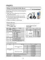
1.1.1 Product Verification
1. Check the name tag to verify that the product matches the model you ordered.
Does the format of the servo drive's name tag match?
Does the format of the servo motor's name tag match?
2. Check the product and options.
Are the type and length of the cables correct?
Does the regenerative resistance conform to the standard?
Is the shape of the shaft end correct?
Is there any abnormality when the oil seal or brake is mounted?
Are the gearbox and the gear ratios correct?
Is the encoder format correct?
3. Check the exterior.
Is there any foreign substance or humidity?
Is there any discoloring, contamination, damage or disconnection of wires?
Are the bolts at joints fastened sufficiently?
Is there any abnormal sound or excessive friction during rotation?
Servo Drive Product Format
Series
Name
Communication
Type
Input
Voltage
Capacity
Encoder Type
Option
Servo
Series
S: Standard I/O
type
N: Network type
A: 220 VAC
B: 400 VAC
001: 100 W 050: 5.0 kW
002: 200 W 075: 7.5 kW
004: 400 W 110: 11.0kW
008: 750 W 150: 15.0kW
010: 1.0 kW
020: 2.0 kW
035: 3.5 kW
A: Quadrature
(Pulse type)
B: Serial
(communication
type)
Exclusive
Option
L7 S A 004 A AA
1. Product Components and Signals
1-2
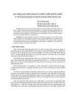
Servo Motor Product Format
Encoder Type
Quadrature(pulse type)
A: Inc. 1024 [P/R]
B: Inc. 2000 [P/R]
C: Inc. 2048 [P/R]
D: Inc. 2500 [P/R]
E: Inc. 3000 [P/R]
F: Inc. 5000 [P/R]
G: Inc. 6000 [P/R]
Serial BISS
(communication type)
N : 19bit S-Turn Abs.
M : 19bit M-Turn Abs.
Servo Motor
Motor Capacity
R3 : 30[W]
R5 : 50[W]
01 : 100[W]
02 : 200[W]
03 : 300[W]
04 : 400[W]
05 : 450[W]
06 : 550/600[W]
07 : 650[W]
08 : 750/800[W]
09 : 850/900[W]
10 : 1.0[kW]
·
·
150 : 15.0[kW]
220 : 22.0[kW]
300 : 30.0[kW]
370 : 37.0[kW]
Motor Shape
S: Solid Shaft
H: Hollow Shaft
B: Assembly
F: Flat Type
Flange Size
A : 40 Flange
B : 60 Flange
C : 80 Flange
D : 100 Flange
E : 130 Flange
F : 180 Flange
G : 220 Flange
H : 250 Flange
J : 280 Flange
Rated RPM
A: 3000 [RPM]
D: 2000 [RPM]
G: 1500 [RPM]
M: 1000 [RPM]
Shaft Cross-section
N: Straight
K: One-sided round
key (standard)
C: C Cut
D: D Cut
T: Tapering
R: Double-sided
round key
H: Hollow Shaft
Oil Seal and Brake
Non-existent: None
attached
1: Oil Seal attached
2: Brake attached
3: Oil Seal and Brake
attached
Gearbox
Specifications
Non-existent:
No gearbox
G1: For general industrial
purposes (Foot Mount)
G2: For general industrial
purposes (Flange Mount)
G3: Precise Gearbox
Gearbox
Classification
03: 1/3
10: 1/10
APM – S B 04 A E K 1 G1 03
1. Product Components and Signals
1-3
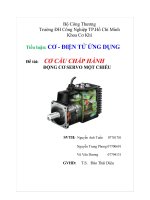
1.1.2 Part Names
Servo Motor
80 Flange or below
80 Flange or below(Flat Type)
130 Flange or higher
Bearing Cap
Shaft
Flange
Frame
Housing
Encoder
Cover
Encoder
Connector
Motor Power
Cable
Motor
Connector
Encoder
Cable
Bearing Cap
Shaft
Flange
Frame
Housing
Encoder
Cover
Encoder
Connector
Motor
Connector
Flange
Shaft
Frame
Power connector
Encoder connector
Mold
Housing
Encoder Cover
1. Product Components and Signals
1-4
Servo Drive
L7SA 001□, L7SA 002□, L7SA 004□
Main power connector (L1,
L2, L3)
Regenerative resistance
connector (B+, B, BI)
When basic installation
is in use short circuit B
and BI terminals
When installing external
resistance install in the
B+ and B terminals
Motor power cable
connector (U, V, W)
Operation keys
(Mode, Up, Down, Set)
Heat sink
Control power connector
(C1, C2)
Ground
CN3:
RS-422 communication
connector
CN2:
Encoder signal connector
CN1:
Control signal connector
Display
Front cover
CN5:
USB connector
CN4:
RS-422 communication
connector
DC reactor connector
(PO, PI)
Short circuit when not used
1. Product Components and Signals
1-5
L7SA 008□, L7SA 010□
CN3:
RS-422 communication
connector
CN2:
Encoder signal connector
CN1:
Control signal connector
Display
Front cover
CN5:
USB connector
CN4:
RS-422 communication
connector
Main power connector
(L1, L2, L3)
Motor power cable
connector (U, V, W)
Heat sink
Control power connector
(C1, C2)
Ground
Operation keys
(Mode, Up, Down, Set)
DC reactor connector
(PO, PI)
Short circuit when not used
Regenerative resistance
connector (B+, B, BI)
When basic installation
is in use short circuit B
and BI terminals.
When installing external
resistance install in the
B+ and B terminals.
1. Product Components and Signals
1-6
L7SA 020□, L7SA 035□
CN3:
RS-422 communication
connector
CN2:
Encoder signal connector
CN1:
Control signal connector
Display
Front cover
CN5:
USB connector
CN4:
RS-422 communication
connector
Main power connector
(L1, L2, L3)
Motor power cable
connector (U, V, W)
Heat sink
Control power connector
(C1, C2)
DC reactor connector
(PO, PI)
Short circuit when not used
Regenerative resistance
connector (B+, B, BI)
When basic installation
is in useshort circuit B
and BI terminals.
When installing external
resistance install in the
B+ and B terminals.
Operation keys
(Mode, Up, Down, Set)
Ground
1. Product Components and Signals
1-7
1.2 System Configuration
1.2.1 Overview
The L7 servo system can be configured in various ways depending on its interface with the
upper level controller.
(1) Position Operation System
The servo is run by pulse commands. You can change the location of the servo motor by
changing command pulses based on a certain transfer unit.
Position
Controller
Speed
Controller
Change
Position
Command
Pulse
Position
Controller
Speed
Controller
Current
Controller
Position Controller
Upper Level Controller
Servo Drive
Servo Motor
Motor
Encoder
Position Feedback
Advantage: The structure of the upper level controller is simple because pulse input is linked to
transfer units.
Disadvantages:
Fast rotation is compromised when a precise transfer unit is used.
Response is low because multiple levels of controllers are used.
(2) Speed Operation System
The servo is run by speed commands. There are two types of speed commands: analog
voltage command and digital speed command.
Position
Controller
Speed
Controller
Change
Speed
Command
Speed
Controller
Current
Controller
Speed Command
Upper Level Controller Servo Drive Servo Motor
Motor
Encoder
Position Feedback
Advantages:
The servo responds quickly.
Precision control is easy.
Disadvantage: The upper level controller is complex.
1. Product Components and Signals
1-8
(3) Torque Operation System
The servo is run by torque commands. Analog voltage-based commands are used.
Position
Controller
Torque
Controller
Change
Torque
Command
Torque
Controller
Current
Controller
Torque Command
Upper Level Controller Servo Drive Servo Motor
Motor
Encoder
Position Feedback
Advantages:
The servo responds quickly.
Precision control is easy.
Disadvantage: The upper level controller is complex.
(4) Operation Mode
The L7 servo drive can be run in torque, speed, and position modes, depending on its
interface with the upper level controller. The operation modes can be switched by
parameters or digital input contact point.
Operation Mode
System Configuration
0
The servo is run on the torque operation system.
1
The servo is run on the speed operation system.
2
The servo is run on the position operation system.
3
The servo is run with the speed and position operation systems as points of
contact.
4
The servo is run with the speed and torque operation systems as points of
contact.
5
The servo is run with the position and torque operation systems as points of
contact.
1. Product Components and Signals
1-9
1.2.2 Wiring Diagram of the Entire CN1 Connector
STOP 48
EMG 18
CWLIM 19
CCWLIM 20
DIR 46
ALMRST 17
SPD3 21
SPD2 22
SPD1 23
SVON 47
ALARM+38
ALARM-39
READY+40
READY-41
ZSPD43
BRAKE44
INPOS
45
50+24V IN
GND2424
ALO016
ALO115
ALO214
GND2425
SPDCOM 27
GND 8
TRQCOM 1
GND 8
Digital Input Digital Output
Command Pulse Input
Analog Input
DC 24V
3.3kΩ
Line Driver
Open Collector
CN1
-10V ~ +10V
Upper Level
Controller
-10V ~ +10V
Analog Speed
Command/Limit
Analog Torque
Command/Limit
Note 1)
(DIA)
(DI9)
(DI8)
(DI7)
(DI6)
(DI5)
(DI4)
(DI3)
(DI2)
(DI1)
(DO1)
(DO2)
(DO3)
(DO4)
(DO5)
Note 1)
Note 1) Input signals DI1 to DIA and output signals DO1 to DO5 are default signals allocated by the factory.
Note 2) ** These are non-allocated signals. You can change their allocation by setting parameters. For more
information, refer to “4.1.6 External Input Signal and Logic Definition” and “4.1.8 External Output Signal and
Logic Definition.”
VLMT**
TLMT**
Note 2)
WARN**
INSPD**
EGEAR1 **
EGEAR2 **
PCON **
GAIN2 **
P_CLR **
T_LMT **
Note 2)
MODE **
ABS_RQ **
ZCLAMP **
MONIT128
MONIT229
GND37
AO32
/AO33
BO30
/BO31
ZO4
/ZO5
SG36
Analog Output
Encoder Pulse Output
Connect to Connector Case
-10V ~ +10V
-10V ~ +10V
Upper Level
Controller
+12VA34
-12VA35
PULCOM 49
PF+ 9
PF- 10
PR+ 11
PR- 12
1. Product Components and Signals
1-10
1.2.3 Example of Position Operation Mode Wiring
STOP 48
EMG 18
CWLIM 19
CCWLIM 20
DIR 46
ALMRST 17
SPD3 21
SPD2 22
SPD1 23
SVON 47
ALARM+38
ALARM-39
READY+40
READY-41
ZSPD43
BRAKE44
INPOS
45
50+24V IN
GND2424
MONIT128
MONIT229
GND37
AO32
/AO33
BO30
/BO31
ZO4
/ZO5
ALO016
ALO115
ALO214
GND2425
PULCOM 49
PF+ 9
PF- 10
PR+ 11
PR- 12
TRQCOM 1
GND 8
SG36
Digital Input Digital Output
Analog Output
Command Pulse Input
Encoder Pulse Output
Analog Input
Connect to Connector Case
DC 24V
3.3kΩ
Line Driver
Open Collector
CN1
-10V ~ +10V
-10V ~ +10V
-10V ~ +10V
Upper
Level
Controller
-10V ~ +10V
Analog
Torque
Limit
Upper
Level
Controller
EGEAR1
**
EGEAR2
**
PCON **
GAIN2 **
P_CLR **
T_LMT **
VLMT**
TLMT**
Note 1)
Note 2)
Note 2)
(DIA)
(DI9)
(DI8)
(DI7)
(DI6)
(DI5)
(DI4)
(DI3)
(DI2)
(DI1)
(DO1)
(DO2)
(DO3)
(DO4)
(DO5)
Note 1)
Note 1) Input signals DI1 to DIA and output signals DO1 to DO5 are default signals allocated by the factory.
Note 2) ** These are non-allocated signals. You can change their allocation by setting parameters. For more
information, refer to “4.1.6 External Input Signal and Logic Definition” and “4.1.8 External Output Signal and
Logic Definition.”
MODE **
ABS_RQ **
ZCLAMP ** WARN**
INSPD**
+12VA34
-12VA35
1. Product Components and Signals
1-11
1.2.4 Example of Speed Operation Mode Wiring
STOP 48
EMG 18
CWLIM 19
CCWLIM 20
DIR 46
ALMRST 17
SPD3 21
SPD2 22
SPD1 23
SVON 47
ALARM+38
ALARM-39
READY+40
READY-41
ZSPD43
BRAKE44
INPOS
45
50+24V IN
GND2424
ALO016
ALO115
ALO214
GND2425
SPDCOM 27
GND 8
TRQCOM 1
GND 8
Digital Input Digital Output
Command Pulse Input
Analog Input
DC 24V
3.3kΩ
Line Driver
Open Collector
CN1
-10V ~ +10V
Upper
Level
Controller
-10V ~ +10V
Analog
Speed
Command
Analog
Torque Limit
Note 1)
(DIA)
(DI9)
(DI8)
(DI7)
(DI6)
(DI5)
(DI4)
(DI3)
(DI2)
(DI1)
(DO1)
(DO2)
(DO3)
(DO4)
(DO5)
Note 1)
Note 1) Input signals DI1 to DIA and output signals DO1 to DO5 are default signals allocated by the factory.
Note 2) ** These are non-allocated signals. You can change their allocation by setting parameters. For more
information, refer to “4.1.6 External Input Signal and Logic Definition” and “4.1.8 External Output Signal and
Logic Definition.”
VLMT**
TLMT**
Note 2)
WARN**
INSPD**
EGEAR1 **
EGEAR2 **
PCON **
GAIN2 **
P_CLR **
T_LMT **
Note 2)
MODE **
ABS_RQ **
ZCLAMP **
MONIT128
MONIT229
GND37
AO32
/AO33
BO30
/BO31
ZO4
/ZO5
SG36
Analog Output
Encoder Pulse Output
Connect to Connector Case
-10V ~ +10V
-10V ~ +10V
Upper
Level
Controller
+12VA34
-12VA35
1. Product Components and Signals
1-12
1.2.5 Example of Torque Operation Mode Wiring
STOP 48
EMG 18
CWLIM 19
CCWLIM 20
DIR 46
ALMRST 17
SPD3 21
SPD2 22
SPD1 23
SVON 47
ALARM+38
ALARM-39
READY+40
READY-41
ZSPD43
BRAKE44
INPOS
45
50+24V IN
GND2424
ALO016
ALO115
ALO214
GND2425
SPDCOM 27
GND 8
TRQCOM 1
GND 8
Digital Input Digital Output
Command Pulse Input
Analog Input
DC 24V
3.3kΩ
Line Driver
Open Collector
CN1
-10V ~ +10V
Upper
Level
Controller
-10V ~ +10V
Analog
Speed Limit
Analog
Torque
Command
Note 1)
(DIA)
(DI9)
(DI8)
(DI7)
(DI6)
(DI5)
(DI4)
(DI3)
(DI2)
(DI1)
(DO1)
(DO2)
(DO3)
(DO4)
(DO5)
Note 1)
Note 1) Input signals DI1 to DIA and output signals DO1 to DO5 are default signals allocated by the factory.
Note 2) ** These are non-allocated signals. You can change their allocation by setting parameters. For more
information, refer to “4.1.6 External Input Signal and Logic Definition” and “4.1.8 External Output Signal and
Logic Definition.”
VLMT**
TLMT**
Note 2)
WARN**
INSPD**
EGEAR1 **
EGEAR2 **
PCON **
GAIN2 **
P_CLR **
T_LMT **
Note 2)
MODE **
ABS_RQ **
ZCLAMP **
MONIT128
MONIT229
GND37
AO32
/AO33
BO30
/BO31
ZO4
/ZO5
SG36
Analog Output
Encoder Pulse Output
Connect to Connector Case
-10V ~ +10V
-10V ~ +10V
Upper
Level
Controller
+12VA34
-12VA35
1. Product Components and Signals
1-13
1.2.6 Examples of Speed / Position Operation Mode Wiring
STOP 48
EMG 18
CWLIM 19
CCWLIM 20
DIR 46
ALMRST 17
SPD3 21
SPD2 22
SPD1 23
SVON 47
ALARM+38
ALARM-39
READY+40
READY-41
ZSPD43
BRAKE44
INPOS
45
50+24V IN
GND2424
ALO016
ALO115
ALO214
GND2425
PULCOM 49
PF+ 9
PF- 10
PR+ 11
PR- 12
SPDCOM 27
GND 8
TRQCOM 1
GND 8
Digital Input Digital Output
Command Pulse Input
Analog Input
DC 24V
3.3kΩ
Line Driver
Open Collector
CN1
-10V ~ +10V
Upper
Level
Controller
-10V ~ +10V
Analog
Speed
Command
Analog
Torque
Limit
Note 1)
(DIA)
(DI9)
(DI8)
(DI7)
(DI6)
(DI5)
(DI4)
(DI3)
(DI2)
(DI1)
(DO1)
(DO2)
(DO3)
(DO4)
(DO5)
Note 1)
Note 1) Input signals DI1 to DIA and output signals DO1 to DO5 are default signals allocated by the factory.
Note 2) ** These are non-allocated signals. You can change their allocation by setting parameters. For more
information, refer to “4.1.6 External Input Signal and Logic Definition” and “4.1.8 External Output Signal and
Logic Definition.”
Note 3) Input Contact Mode = ON: Speed Control Mode, Mode = OFF: Position Operation Mode
VLMT**
TLMT**
Note 2)
WARN**
INSPD**
EGEAR1 **
EGEAR2 **
PCON **
GAIN2 **
P_CLR **
T_LMT **
Note 2)
MODE **
ABS_RQ **
ZCLAMP **
MONIT128
MONIT229
GND37
AO32
/AO33
BO30
/BO31
ZO4
/ZO5
SG36
Analog Output
Encoder Pulse Output
Connect to Connector Case
-10V ~ +10V
-10V ~ +10V
Upper
Level
Controller
+12VA34
-12VA35
Note 3)