Camry Repair Manual BRAKE
Bạn đang xem bản rút gọn của tài liệu. Xem và tải ngay bản đầy đủ của tài liệu tại đây (928.82 KB, 72 trang )
BR0A9–01
–BRAKE BRAKE SYSTEM
BR–1
2024AuthorĂ: DateĂ:
BRAKE SYSTEM
PRECAUTION
1. Care must be taken to replace each part properly as it could affect the performance of the brake
system and result in a driving hazard. Replace the parts with parts having the same part number
or equivalent.
2. It is very important to keep parts and the area clean when repairing the brake system.
3. If the vehicle is equipped with a mobile communication system, refer to the precautions in the
IN section.
BR0AA–03
BR–2
–BRAKE TROUBLESHOOTING
2025AuthorĂ: DateĂ:
TROUBLESHOOTING
PROBLEM SYMPTOMS TABLE
Use the table below to help you find the cause of the problem. The numbers indicate the priority of the likely
cause of the problem. Check each part in order. If necessary, replace these parts.
Symptom CAUSE PAGE
Low pedal or spongy pedal
1. Fluid leaks for brake system
2. Air in brake system
3. Piston seals (Worn or damaged)
4. Rear brake shoe clearance (Out of adjustment)
5. Master cylinder (Faulty)
6. Booster push rod (Out of adjustment)
DI–536
BR–4
BR–24
BR–31
BR–39
BR–35
BR–9
BR–20
Brake drag
1. Brake pedal freeplay (Minimal)
2. Parking brake lever travel (Out of adjustment)
3. Parking brake wire (Sticking)
4. Rear brake shoe clearance (Out of adjustment)
5. Pad or lining (Cracked or distorted)
6. Piston (Stuck)
7. Piston (Frozen)
8. Anchor, return or tension spring (Faulty)
9. Booster push rod (Out of adjustment)
10.Vacuum leaks for booster system
11.Master cylinder (Faulty)
BR–5
BR–8
BR–35
BR–21
BR–31
BR–36
BR–24
BR–31
BR–39
BR–24
BR–31
BR–39
BR–31
BR–45
BR–20
BR–18
BR–9
Brake pull
1. Piston (Stuck)
2. Pad or lining (Oily)
3. Piston (Frozen)
4. Disc (Scored)
5. Pad or lining (Cracked or distorted)
BR–24
BR–31
BR–39
BR–21
BR–31
BR–36
BR–24
BR–31
BR–39
BR–24
BR–39
BR–21
BR–31
BR–36
–BRAKE TROUBLESHOOTING
BR–3
2026AuthorĂ: DateĂ:
Hard pedal but brake inefficient
1. Fluid leaks for brake system
2. Air in brake system
3. Pad or lining (Worn)
4. Pad or lining (Cracked or distorted)
5. Rear brake shoe clearance (Out of adjustment)
6. Pad or lining (Oily)
7. Pad or lining (Glazed)
8. Disc (Scored)
9. Booster push rod (Out of adjustment)
10.Vacuum leaks for booster system
DI–536
BR–4
BR–21
BR–31
BR–36
BR–21
BR–31
BR–36
BR–35
BR–21
BR–31
BR–36
BR–21
BR–31
BR–36
BR–24
BR–39
BR–20
BR–18
Noise from brakes
1. Pad or lining (Cracked or distorted)
2. Installation bolt (Loose)
3. Disc (Scored)
4. Pad support plate (Loose)
5. Sliding pin (Worn)
6. Pad or lining (Dirty)
7. Pad or lining (Glazed)
8. Anchor, return or tension spring (Faulty)
9. Anti–squeal shim (Damaged)
10.Shoe hold–down spring (Damaged)
BR–21
BR–31
BR–36
BR–24
BR–39
BR–24
BR–39
BR–21
BR–36
BR–24
BR–39
BR–21
BR–31
BR–36
BR–21
BR–31
BR–36
BR–31
BR–45
BR–21
BR–36
BR–31
BR–45
F05595
F05596
BR0AB–03
F05597
R00252
BR–4
–BRAKE BRAKE FLUID
2027AuthorĂ: DateĂ:
BRAKE FLUID
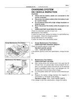
BLEEDING
HINT:
If any work is done on the brake system or if air is suspected in
the brake lines, bleed the air from the system.
NOTICE:
Do not let brake fluid remain on a painted surface. Wash it
off immediately.
1. FILL BRAKE RESERVOIR WITH BRAKE FLUID
Check the fluid level in the reservoir after bleeding each wheel.
Add fluid, if necessary.
Fluid: SAEJ1703 or FMVSS No.116 DOT 3
2. BLEED MASTER CYLINDER
HINT:
If the master cylinder has been disassembled or if the reservoir
becomes empty, bleed the air from the master cylinder.
(a) Disconnect the 2 brake lines from the master cylinder.
(b) Slowly depress the brake pedal and hold it.
(c) Block off the outlet plugs with your fingers, and release
the brake pedal.
(d) Repeat (b) and (c) 3 or 4 times.
3. CONNECT VINYL TUBE TO BRAKE CALIPER OR
WHEEL CYLINDER BLEEDER PLUG
Insert the other end of the tube in a half–full container of brake
fluid.
NOTICE:
Bleed air of the rear brake first. If front brake is bled first,
rear brake air cannot be bled.
4. BLEED BRAKE LINE
(a) Slowly depress the brake pedal several times.
(b) While an assistant depresses the pedal, loosen the
bleeder plug until fluid starts to run out. Then tighten the
bleeder plug.
(c) Repeat this procedure until there are no more air bubbles
in the fluid.
Torque: (Bleeder plug)
8.3 N·m (85 kgf·cm, 74 in.·lbf)
5. REPEAT PROCEDURE FOR EACH WHEEL
R00954
Stop Light
Switch
Push Rod
Pedal Height
BR0YH–01
R00935
Pedal Freeplay
–BRAKE BRAKE PEDAL
BR–5
2028AuthorĂ: DateĂ:
BRAKE PEDAL
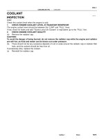
ON–VEHICLE INSPECTION
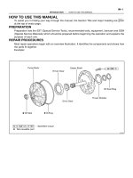
1. CHECK PEDAL HEIGHT
Pedal height from asphalt sheet:
152.0 – 162.0 mm (5.984 – 6.378 in.)
2. IF NECESSARY, ADJUST PEDAL HEIGHT
(a) Disconnect the connector from the stop light switch.
(b) Loosen the stop light switch lock nut and remove the stop
light switch.
(c) Loosen the push rod lock nut.
(d) Adjust the pedal height by turning the pedal push rod.
(e) Tighten the push rod lock nut.
Torque: 25 N·m (260 kgf·cm, 19 ft·lbf)
(f) Install the stop light switch and turn it until it lightly con-
tacts the pedal stopper.
(g) Push in the brake pedal 5–15 mm (0.20–0.59 in.), turn the
stop light switch to lock the nut in the position where the
stop light goes off.
(h) Connect the connector to the stop light switch.
(i) After installation, push in the brake pedal 5–15 mm
(0.20–0.59 in.), check that stop light lights up.
(j) Connect the connector to the stop light switch.
(k) After adjusting the pedal height, check the pedal freeplay.
3. CHECK PEDAL FREEPLAY
(a) Stop the engine and depress the brake pedal several
times until there is no more vacuum left in the booster.
(b) Push in the pedal by hand until the resistance begins to
be felt, then measure the distance.
Pedal freeplay: 1 – 6 mm (0.04 – 0.24 in.)
HINT:
The freeplay to the 1st resistance is due to the play between the
clevis and pin. This is magnified up to 1 – 6 mm (0.04 – 0.24 in.)
at the pedal.
If incorrect, check the stop light switch clearance.
If the clearance is OK, then troubleshoot the brake system.
Stop light switch clearance:
0.5 – 2.4 mm (0.020 – 0.094 in.)
R00934
Pedal Reserve Distance
BR–6
–BRAKE BRAKE PEDAL
2029AuthorĂ: DateĂ:
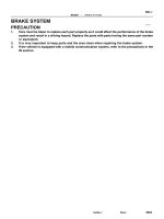
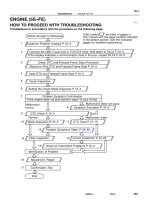
4. CHECK PEDAL RESERVE DISTANCE
(a) Release the parking brake.
(b) With the engine running, depress the pedal and measure
the pedal reserve distance, as shown.
Pedal reserve distance from asphalt sheet at 490 N
(50 kgf, 110.2 lbf): More than 70 mm (2.76 in.)
If the reserve distance is incorrect, troubleshoot the brake sys-
tem.
BR0YI–01
F07004
Lower Panel Insert
S Bushing
Clip
Clevis Pin
No.1 Lower Panel
Return Spring
Cushion Plate
Collar
Brake Pedal
Cowl Side Trim
Front Opening Cover
Brake Pedal
Inside Scuff Plate
M/T:
Stop Light Switch
Wave Washer
Cruise Control ECU
Lithium soap base glycol grease
13 (130, 9)
5.0 (51, 44 in.·lbf)
13 (130, 9)
Pedal Pad
Pedal Pad
S Bushing
A/T:
39 (400, 29)
: Specified torqueN·m (kgf·cm, ft·lbf)
S Non–reusable part
Brake Pedal Bracket
–BRAKE BRAKE PEDAL
BR–7
2030AuthorĂ: DateĂ:
COMPONENTS
W03254
W03255
Lock Nut
Adjusting Nut
BR0AD–03
BR–8
–BRAKE PARKING BRAKE LEVER
2031AuthorĂ: DateĂ:
PARKING BRAKE LEVER
ON–VEHICLE INSPECTION
1. CHECK THAT PARKING BRAKE LEVER TRAVEL
Pull the parking brake lever all the way up, and count the num-
ber of clicks.
Parking brake lever travel at 196 N (20 kgf, 44.1 lbf):
5 – 8 clicks
If incorrect, adjust the parking brake.
2. IF NECESSARY, ADJUST PARKING BRAKE LEVER
TRAVEL
HINT:
Before adjusting the parking brake lever travel, make sure that
the rear brake shoe clearance has been adjusted. For shoe
clearance adjustment, see step 2 on page BR–35 or step 1 on
page BR–48.
(a) Remove the console box.
(b) Loosen the lock nut and adjust the adjusting nut until the
lever travel is correct.
(c) Tighten the lock nut.
Torque: 5.4 N·m (55 kgf·cm, 48 in.·lbf)
(d) Install the console box.
BR0AE–02
Z19120
w/ ABS (& TRAC)
2–way
15 (155, 11)
13 (130, 9)
Master Cylinder
S Gasket
Brake Booster
N·m (kgf·cm, ft·lbf) : Specified torque
S Non–reusable part
w/o ABS
3–way
W03569
N·m (kgf·cm, ft·lbf) : Specified torque
Lithium soap base glycol grease
Grommet
Cylinder Body
No. 2 Piston
No. 1 Piston
Spring
Spring
Cap
Strainer
Reservoir
Grommet
Straight Pin
Reservoir Set Screw
1.7 (18, 16 in.·lbf)
w/ TRAC
–BRAKE BRAKE MASTER CYLINDER
BR–9
2032AuthorĂ: DateĂ:
BRAKE MASTER CYLINDER
COMPONENTS
Z19122
w/o ABS
w/ ABS
Cap
Strainer
Reservoir
No. 2 Piston and Spring
No. 1 Piston and Spring
Cylinder Body
Stopper Bolt
S Gasket
Reservoir Set Screw
Grommet
Snap Ring
Grommet
Cap
Strainer
Reservoir
Reservoir Set Screw
Cylinder Body
S Gasket
Stopper Bolt
Grommet
Grommet
No. 1 Piston and Spring
No. 2 Piston and Spring
Snap Ring
Lithium soap base glycol grease
S Non–reusable part
N·m (kgf·cm, ft·lbf)
: Specified torque
1.7 (18, 16 in.·lbf)
10 (100, 7)
1.7 (18, 16 in.·lbf)
10 (100, 7)
BR–10
–BRAKE BRAKE MASTER CYLINDER
2033AuthorĂ: DateĂ:
BR0AF–03
W04697
SST
R11405
–BRAKE BRAKE MASTER CYLINDER
BR–11
2034AuthorĂ: DateĂ:
REMOVAL
1. DISCONNECT LEVEL WARNING SWITCH CONNEC-
TOR
2. TAKE OUT FLUID WITH SYRINGE
NOTICE:
Do not let brake fluid remain on a painted surface. Wash it
off immediately.
3. DISCONNECT BRAKE LINES
(a) w/ ABS (& TRAC):
Using SST, disconnect the 4 brake lines.
SST 09023–00100
Torque: 15 N·m (155 kgf·cm, 11 ft·lbf)
(b) w/o ABS:
Using SST, disconnect the 5 brake lines.
SST 09023–00100
Torque: 15 N·m (155 kgf·cm, 11 ft·lbf)
4. REMOVE MASTER CYLINDER
Remove the 2 nuts, and pull out the 2 or 3–way, master cylinder
and gasket.
Torque: 13 N·m (130 kgf·cm, 9 ft·lbf)
BR0AG–02
R11406
Soft Jows
R11407
Soft Jows
R12236
A
BR–12
–BRAKE BRAKE MASTER CYLINDER
2035AuthorĂ: DateĂ:
DISASSEMBLY
1. REMOVE RESERVOIR
(a) Remove the set screw and pull out the reservoir.
Torque: 1.7 N·m (18 kgf·cm, 16 in.·lbf)
(b) Remove the cap and strainer from the reservoir.
2. REMOVE 2 GROMMETS
3. Except w/ TRAC:
PLACE CYLINDER IN VISE
4. w/o TRAC:
REMOVE PISTON STOPPER BOLT
Using a screwdriver, push the pistons in all the way and remove
the piston stopper bolt and gasket.
HINT:
Tape the screwdriver tip before use.
Torque: 10 N·m (100 kgf·cm, 7 ft·lbf)
5. w/o TRAC:
REMOVE 2 PISTONS AND SPRINGS
(a) Push in the piston with a screwdriver and remove the
snap ring with snap ring pliers.
HINT:
Tape the screwdriver tip before use.
(b) Remove the No. 1 piston and spring by hand, pulling
straight out, not at an angle.
NOTICE:
S If pulled out and installed at an angle, there is a possi-
bility that the cylinder bore could be damaged.
S At the time of reassembly, please refer to the follow-
ing item.
Be careful not to damage the rubber lips on the pis-
tons.
(c) Place a rag and 2 wooden blocks on the work table, and
lightly tap the cylinder flange against the block edges until
the No. 2 piston drops out of the cylinder.
HINT:
Make sure that the distance (A) from the rag to the top of the
blocks is at least 100 mm (3.94 in.).
W03570
W03590
–BRAKE BRAKE MASTER CYLINDER
BR–13
2036AuthorĂ: DateĂ:
6. w/ TRAC:
REMOVE 2 PISTONS AND SPRINGS
(a) Push in the piston with a screwdriver, and remove the 2
straight pins by turning over the cylinder body.
HINT:
Tape the screwdriver tip before use.
(b) Remove the 2 pistons and springs by hand, pulling
straight out, not at an angle.
NOTICE:
S If pulled out and installed at an angle, there is a possi-
bility that the cylinder bore could be damaged.
S At the time of reassembly, be careful not to damage
the rubber lips on the pistons.
HINT:
At the time of reassembly, insert the pistons with elliptic hole
facing vertically.
BR0AH–01
BR–14
–BRAKE BRAKE MASTER CYLINDER
2037AuthorĂ: DateĂ:
INSPECTION
HINT:
Clean the disassembled parts with compressed air.
1. INSPECT CYLINDER BORE FOR RUST OR SCORING
2. INSPECT CYLINDER FOR WEAR OR DAMAGE
If necessary, clean or replace the cylinder.
BR0AI–02
–BRAKE BRAKE MASTER CYLINDER
BR–15
2038AuthorĂ: DateĂ:
REASSEMBLY
Reassembly is in the reverse order of disassembly (See page BR–12).
NOTICE:
Apply lithium soap base glycol grease to the rubber parts indicated by the arrows
(See page BR–9).
BR0AJ–02
BR–16
–BRAKE BRAKE MASTER CYLINDER
2039AuthorĂ: DateĂ:
INSTALLATION
Installation is in the reverse order of removal (See page BR–11).
HINT:
S Before installation, adjust length of the brake booster push rod (See page BR–20).
S After installation, fill the brake reservoir with brake fluid, bleed the brake system and check for leaks
(See page BR–4).
S Check and adjust brake pedal (See page BR–5).
BR2237
BR0AK–03
BR2238
1st
3rd
2nd
GOOD
NO GOOD
–BRAKE BRAKE BOOSTER ASSEMBLY
BR–17
2040AuthorĂ: DateĂ:
BRAKE BOOSTER ASSEMBLY
ON–VEHICLE INSPECTION
1. OPERATING CHECK
(a) Depress the brake pedal several times with the engine off
and check that there is no change in the pedal reserve
distance.
(b) Depress the brake pedal and start the engine. If the pedal
goes down slightly, operation is normal.
2. AIR TIGHTNESS CHECK
(a) Start the engine and stop it after 1 or 2 minutes. Depress
the brake pedal several times slowly.
If the pedal goes down farthest the 1st time, but gradually rises
after the 2nd or 3rd time, the booster is air tight.
(b) Depress the brake pedal while the engine is running, and
stop the engine with the pedal depressed. If there is no
change in the pedal reserve travel after holding the pedal
for 30 seconds, the booster is air tight.
BR0AL–03
Z19121
Master Cylinder
SGasket
Brake Booster
SGasket
Pin
Clip
Clevis
2–way
S Non–reusable part
N·m (kgf·cm, ft·lbf) : Specified torque
w/ ABS (& TRAC)
3–way
15 (155, 11)
13 (130, 9)
25 (260, 19)
13 (130, 9)
BR–18
–BRAKE BRAKE BOOSTER ASSEMBLY
2041AuthorĂ: DateĂ:
COMPONENTS
BR0AM–03
F06431
–BRAKE BRAKE BOOSTER ASSEMBLY
BR–19
2042AuthorĂ: DateĂ:
REMOVAL
1. REMOVE AIR CLEANER COVER WITH AIR CLEANER
HOSE
2. REMOVE MASTER CYLINDER (See page BR–11)
3. REMOVE CHARCOL CANISTER
4. DISCONNECT VACUUM HOSE FROM BRAKE
BOOSTER
5. REMOVE PEDAL RETURN SPRING
6. REMOVE CLIP AND CLEVIS PIN
7. REMOVE BRAKE BOOSTER, GASKET AND CLEVIS
(a) Remove the 4 nuts and clevis.
(b) Pull out the brake booster and gasket.
BR0AN–03
F03521
SST
Gasket
R11347
SST
BR–20
–BRAKE BRAKE BOOSTER ASSEMBLY
2043AuthorĂ: DateĂ:
INSTALLATION
1. INSTALL BRAKE BOOSTER
(a) Install the booster and a new gasket.
(b) Install the clevis to the operating rod.
(c) Install and torque the booster installation nuts.
Torque: 13 N·m (130 kgf·cm, 9 ft·lbf)
(d) Install the clevis, and torque the lock nut.
Torque: 25 N·m (260 kgf·cm, 19 ft·lbf)
(e) Install the clevis pin into the clevis and brake pedal, and
install the clip to the clevis pin.
(f) Install the pedal return spring.
2. ADJUST LENGTH OF BOOSTER PUSH ROD
(a) Install a new gasket on the master cylinder.
(b) Set the SST on the gasket, and lower the pin until its tip
slightly touches the piston.
SST 09737–00010
(c) Turn the SST upside down, and set it on the booster.
SST 09737–00010
(d) Measure the clearance between the booster push rod
and pin head (SST).
Clearance: 0 mm (0 in.)
(e) Adjust the booster push rod length until the push rod light-
ly touches the pin head.
3. INSTALL CHARCOAL CANISTER TO ORIGINAL POSI-
TION
4. INSTALL MASTER CYLINDER (See page BR–16)
5. INSTALL AIR CLEANER COVER WITH AIR CLEANER
HOSE
6. CONNECT VACUUM HOSE TO BRAKE BOOSTER
7. FILL BRAKE RESERVOIR WITH BRAKE FLUID AND
BLEED BRAKE SYSTEM (See page BR–4)
8. CHECK FOR FLUID LEAKAGE
9. CHECK AND ADJUST BRAKE PEDAL
(See page BR–5)
10. DO OPERATIONAL CHECK (See page BR–17)
BR0AO–03
F06983
F07224
F07225
Anti–squeal Shim
Inner Anti–squeal Shim
Anti–squeal Spring
Pad Support Plate
Inner Pad
Outer Pad
1MZ–FE engine:
5S–FE engine:
Anti–squeal Shim
Inner Anti–squeal Shim
Pad Wear Indicator Plate
Outer Pad
Pad Support Plate
Inner Pad
Disc brake grease
N·m (kgf·cm, ft·lbf)
: Specified torque
34 (350, 25)
34 (350, 25)
–BRAKE FRONT BRAKE PAD
BR–21
2044A uthorĂ: DateĂ:
FRONT BRAKE PAD
COMPONENTS
BR0AP–03
F07213
R02874
BR–22
–BRAKE FRONT BRAKE PAD
2045A uthorĂ: DateĂ:
REPLACEMENT
1. REMOVE FRONT WHEEL
Remove the wheel and temporarily fasten the disc with hub
nuts.
2. INSPECT PAD LINING THICKNESS
Check the pad thickness through the caliper inspection hole
and replace the pads if they are not within the specification.
Minimum thickness: 1.0 mm (0.039 in.)
3. LIFT UP CALIPER
(a) Remove the bolt and flexible hose from the bracket.
(b) 5S–FE engine:
Hold the sliding pin on the bottom and loosen the installa-
tion bolt, and remove the installation bolt.
(c) 1MZ–FE engine:
Remove the bottom side installation bolt.
(d) Lift up the caliper and suspend it securely.
HINT:
Do not disconnect the flexible hose from the caliper.
4. 5S–FE engine:
REMOVE 2 ANTI–SQUEAL SPRINGS
5. REMOVE 2 BRAKE PADS
6. REMOVE 4 ANTI–SQUEAL SHIMS
7. 1MZ–FE engine:
REMOVE PAD WEAR INDICATOR PLATE
8. 1MZ–FE engine:
REMOVE 2 PAD SUPPORT PLATES
9. 5S–FE engine:
REMOVE 4 PAD SUPPORT PLATES
NOTICE:
The anti–squeal springs and support plates can be used
again provided that they have sufficient rebound, no de-
formation, cracks or wear, and have had all rust, dirt and
foreign particles cleaned off.
10. CHECK DISC THICKNESS AND RUNOUT
(See page BR–28)
11. INSTALL 2 OR 4 PAD SUPPORT PLATES
12. INSTALL NEW PADS
NOTICE:
When replacing worn pads, the anti–squeal shims and
wear indicator plates must be replaced together with the
pads.
R00595
R02981
–BRAKE FRONT BRAKE PAD
BR–23
2046A uthorĂ: DateĂ:
(a) 1MZ–FE engine:
Install a pad wear indicator plate on the inner pad.
(b) Apply disc brake grease to both sides of the inner anti–
squeal shims (See page BR–21).
(c) Install the 2 anti–squeal shims on each pad.
(d) Install inner pad with the pad wear indicator plate facing
upward.
(e) Install inner pad.
(f) Install outer pad.
NOTICE:
There should be no oil or grease adhering to the friction
surfaces of the pads or the disc.
(g) 5S–FE engine:
Install the 2 anti–squeal springs.
13. INSTALL CALIPER
(a) Draw out a small amount of brake fluid from the reservoir.
(b) Press in the piston with a hammer handle or similar imple-
ment.
HINT:
If the piston is difficult to push in, loosen the bleeder plug and
push in the piston while letting some brake fluid escape.
(c) Install the caliper.
(d) 5S–FE engine:
Hold the sliding pin and torque the installation bolt.
(e) 1MZ–FE engine:
Install the installation bolt.
Torque: 34 N·m (350 kgf·cm, 25 ft·lbf)
(f) Install the flexible hose and bolt to the bracket.
Torque: 29 N·m (300 kgf·cm, 21 ft·lbf)
14. INSTALL FRONT WHEEL
Torque: 103 N·m (1,050 kgf·cm, 76 ft·lbf)
15. DEPRESS BRAKE PEDAL SEVERAL TIMES
16. CHECK THAT FLUID LEVEL IS AT MAX LINE
BR0AQ–02
F07212
Caliper
Torque Plate
Disc
SGasket
Piston
Piston Seal
Sliding Pin
SDust Boot
Pad Support Plate
Sliding Pin
SSliding Bushing
SDust Boot
Anti–squeal Spring
Outer Pad
Anti–squeal Shim
Inner Anti–squeal Shim
Inner Pad
Disc brake grease
Lithium soap base glycol grease
S Non–reusable part
N·m (kgf·cm, ft·lbf)
: Specified torque
Bleeder Plug
Boot
Set Ring
5S–FE engine:
34 (350, 25)
107 (1,090, 79)
29 (300, 21)
8.3 (85, 74 in.·lbf)
29 (300, 21)
BR–24
–BRAKE FRONT BRAKE CALIPER
2047AuthorĂ: DateĂ:
FRONT BRAKE CALIPER
COMPONENTS
F07226
1MZ–FE engine:
Caliper
Torque Plate
Disc
Piston
Sliding pin
SSliding Bushing
SDust Boot
Pad Support Plate
Sliding Pin
SDust Boot
Pad Wear Indicator Plate
Inner Pad
Piston Seal
Boot
Set Ring
Outer Pad
Inner Anti–squeal Shim
Anti–squeal Shim
Disc Brake grease
Lithium soap base glycol grease
S Non–reusable part
N·m (kgf·cm, ft·lbf)
: Specified torque
Bleeder Plug
34 (350, 25)
107 (1,090, 79)
29 (300, 21)
8.3 (85, 74 in.·lbf)
29 (300, 21)
SGasket
–BRAKE FRONT BRAKE CALIPER
BR–25
2048AuthorĂ: DateĂ: