Nandhopper 1 bit noise synth
Bạn đang xem bản rút gọn của tài liệu. Xem và tải ngay bản đầy đủ của tài liệu tại đây (463.12 KB, 8 trang )
/>Home Sign Up! Explore Community Submit
Nandhopper 1-Bit Noise Synth
by kylemcdonald on December 17, 2008
Table of Contents
intro: Nandhopper 1-Bit Noise Synth . . . . . . . . . . . . . . . . . . . . . . . . . . . . . . . . . . . . . . . . . . . . . . . . . . . . . . . . . . . . . . . . . . . . . . . . . . . . . . . . . . . . . . . . . . . . . . 2
step 1: Materials . . . . . . . . . . . . . . . . . . . . . . . . . . . . . . . . . . . . . . . . . . . . . . . . . . . . . . . . . . . . . . . . . . . . . . . . . . . . . . . . . . . . . . . . . . . . . . . . . . . . . . . . . . . . . 2
Tools . . . . . . . . . . . . . . . . . . . . . . . . . . . . . . . . . . . . . . . . . . . . . . . . . . . . . . . . . . . . . . . . . . . . . . . . . . . . . . . . . . . . . . . . . . . . . . . . . . . . . . . . . . . . . . . . . . . . 2
Materials . . . . . . . . . . . . . . . . . . . . . . . . . . . . . . . . . . . . . . . . . . . . . . . . . . . . . . . . . . . . . . . . . . . . . . . . . . . . . . . . . . . . . . . . . . . . . . . . . . . . . . . . . . . . . . . . . . 2
Extra . . . . . . . . . . . . . . . . . . . . . . . . . . . . . . . . . . . . . . . . . . . . . . . . . . . . . . . . . . . . . . . . . . . . . . . . . . . . . . . . . . . . . . . . . . . . . . . . . . . . . . . . . . . . . . . . . . . . . 2
step 2: Make FSRs . . . . . . . . . . . . . . . . . . . . . . . . . . . . . . . . . . . . . . . . . . . . . . . . . . . . . . . . . . . . . . . . . . . . . . . . . . . . . . . . . . . . . . . . . . . . . . . . . . . . . . . . . . . 2
step 3: Prototype: Make a Square Wave . . . . . . . . . . . . . . . . . . . . . . . . . . . . . . . . . . . . . . . . . . . . . . . . . . . . . . . . . . . . . . . . . . . . . . . . . . . . . . . . . . . . . . . . . . . . 3
step 4: Prototype: Make the Circuit . . . . . . . . . . . . . . . . . . . . . . . . . . . . . . . . . . . . . . . . . . . . . . . . . . . . . . . . . . . . . . . . . . . . . . . . . . . . . . . . . . . . . . . . . . . . . . . . 4
step 5: Solder Everything Together . . . . . . . . . . . . . . . . . . . . . . . . . . . . . . . . . . . . . . . . . . . . . . . . . . . . . . . . . . . . . . . . . . . . . . . . . . . . . . . . . . . . . . . . . . . . . . . 5
step 6: Plug it In and Finalize . . . . . . . . . . . . . . . . . . . . . . . . . . . . . . . . . . . . . . . . . . . . . . . . . . . . . . . . . . . . . . . . . . . . . . . . . . . . . . . . . . . . . . . . . . . . . . . . . . . . 7
step 7: Variations and Notes . . . . . . . . . . . . . . . . . . . . . . . . . . . . . . . . . . . . . . . . . . . . . . . . . . . . . . . . . . . . . . . . . . . . . . . . . . . . . . . . . . . . . . . . . . . . . . . . . . . . 7
Variations . . . . . . . . . . . . . . . . . . . . . . . . . . . . . . . . . . . . . . . . . . . . . . . . . . . . . . . . . . . . . . . . . . . . . . . . . . . . . . . . . . . . . . . . . . . . . . . . . . . . . . . . . . . . . . . . . 7
Notes . . . . . . . . . . . . . . . . . . . . . . . . . . . . . . . . . . . . . . . . . . . . . . . . . . . . . . . . . . . . . . . . . . . . . . . . . . . . . . . . . . . . . . . . . . . . . . . . . . . . . . . . . . . . . . . . . . . . 7
Related Instructables . . . . . . . . . . . . . . . . . . . . . . . . . . . . . . . . . . . . . . . . . . . . . . . . . . . . . . . . . . . . . . . . . . . . . . . . . . . . . . . . . . . . . . . . . . . . . . . . . . . . . . . . . . . 7
Advertisements . . . . . . . . . . . . . . . . . . . . . . . . . . . . . . . . . . . . . . . . . . . . . . . . . . . . . . . . . . . . . . . . . . . . . . . . . . . . . . . . . . . . . . . . . . . . . . . . . . . . . . . . . . . . . . . 8
Customized Instructable T-shirts . . . . . . . . . . . . . . . . . . . . . . . . . . . . . . . . . . . . . . . . . . . . . . . . . . . . . . . . . . . . . . . . . . . . . . . . . . . . . . . . . . . . . . . . . . . . . . . . 8
Comments . . . . . . . . . . . . . . . . . . . . . . . . . . . . . . . . . . . . . . . . . . . . . . . . . . . . . . . . . . . . . . . . . . . . . . . . . . . . . . . . . . . . . . . . . . . . . . . . . . . . . . . . . . . . . . . . . . . 8
/>intro: Nandhopper 1-Bit Noise Synth
Make a cute + expressive 1-bit noise synthesizer with a logic gate and a few other spare parts.
Watch a demo video to get a better idea of what I mean, or listen to some improvisations: 3 2 1.
step 1: Materials
Here are things you'll to do it exactly the same way I did. Some things, like capacitor size, will vary. Other things could be totally different (you might try a different logic
chip, for example).
Tools
Soldering iron + solder
Hot glue gun + glue
Knife/razor
Wire Cutter
Breadboard
Materials
4093 (Quad, 2-input Schmitt trigger NAND gate)
1/8" stereo miniplug connector
9 V battery connector
Small capacitors (I used 220 pF monolothic capacitors)
Single sided copper clad
Conductive foam (comes with microcontrollers and DIP chips)
Wire
Extra
Oscilloscope
Power supply (for watching current draw)
Multimeter
Sound system or headphones
step 2: Make FSRs
The interface to this device consists of four force sensing resistors. They can be anywhere from about 2x2 cm to 4x4 cm. If they're bigger, just make sure the wire is
longer.
Plusea makes some really cool DIY FSRs, but I used my own style, because I don't have the same materials available. For Plusea's FSRs, you're working with around
200 ohms - 200 kiloohms max. For mine, you're working with 5-15 megaohms max. Commercial FSRs are in a similar range (e.g., this one is around 20 megaohms
without a load). This maximum resistance is important to keep in mind when you're selecting capacitors.
/>Image Notes
1. Conductive foam
2. Single sided copper clad
Image Notes
1. Wires soldered to copper clad
2. Conductive foam
Image Notes
1. Completely assembled FSRs
step 3: Prototype: Make a Square Wave
NAND gates have two inputs and one output, and the 4093 has four NAND gates on it. Here's how they're connected. When both inputs are high, the output is low. In
every other situation the output is high. The 4093 also has Schmitt triggers on its inputs, which helps make it resilient to noise and more likely to oscillate regularly.
There are a few ways to get a NAND gate to give you a square wave. We'll use a way that requires one gate, resistor, and capacitor per oscillator:
Wire one input to high (9 V)
Connect one input to ground via a capacitor
Connect the output to the grounded input via a resistor
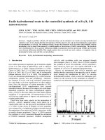
If you watch the output of this gate on an oscilloscope/listen, and switch out capacitor and resistor values, you'll notice you can approximate the frequency of the square
wave by f = (1 / (r x c)). For example, when c = 470 pf and r = 10 megaohms, f = 212 Hz (measured at 250 Hz). This is where those numbers maximum resistance
numbers come in handy for getting an idea of what kind of capacitance value to choose.
In short, if you use this circuit and change the resistance you can change the frequency. Furthermore, you can turn it on and off by wiring input 1 to ground instead of
high.
/>Image Notes
1. 4093 NAND
2. Ground
3. Power (9 V)
4. 10 megaohm feedback resistor from output to input 2
5. 470 pF capacitor to ground on input 2
6. One hole off, but it's supposed to be input 1 tied to high.
Image Notes
1. Close enough to 212 Hz :)
step 4: Prototype: Make the Circuit
There are two main approaches to making this synth.
Figure out what you want in advance, and draw up a circuit that works like that.
Make some sound, and start intuitively adding and removing components however you feel.
Surprisingly, the second approach works really well sometimes. The first Nandhopper I made happened that way, and I think it's the most interesting. Unfortunately, if you
do things the second way it might be really difficult to get the circuit off the breadboard and onto the chip. When you put everything on the chip capacitance changes
slightly between everything, so anything that's fine-tuned might not work anymore.
The first approach is a lot more predictable and repeatable, so I'll describe two layouts that have come from that perspective.
One layout just uses each of the four NAND gates as independent square wave synthesizers. In my experience, they're not genuinely independent and there is always
some sort of leakage between the channels which can make things really interesting. Each pair of gates is mixed into one of the stereo outputs.
The other layout uses two stages: one driving oscillator, that is always running, and three oscillators stuck in a circular/triangular feedback loop. That's the one I
breadboarded here.
Pick one of these, or design your own (or improvise your own, according to your ear).
/>Image Notes
1. Feedback stage
2. Driving stage
Image Notes
1. FSRs
2. Audio output
3. One resistor for connecting the driving oscillator to the feedback loop, one for
completing the feedback loop.
4. Driving oscillator (one input is tied to 9 V)
step 5: Solder Everything Together
Now that everything works on the breadboard, we're going to move it over to the chip.
Start with the power connector. Leave maybe ten centimeters of wire, just in case something goes wrong and you need to cut it off and reuse it. When you solder the
ground and 9 V in place, it will help remind you where things are.
From here, I like "transplanting" the circuit: you have the breadboard next to the chip you're soldering onto, and slowly move components from the breadboard to the chip.
This is one way to make sure you haven't forgotten anything. Make sure you don't forget that the orientation is different if your chip is upside-down and your breadboard
is right-side-up!
Next, add the capacitors. I wrap the legs around the chip so it stays in place, then solder them on once they're where I want. One of the capacitors might have to stretch if
it's going to ground, just make sure the leg doesn't touch anything it shouldn't.
Next, add any extra wires. If you're doing the independent oscillator design, you'll need wires for giving each gate its logic high.
Finally, add your resistors and FSRs. Resistors can be fit snugly under the chip, FSRs should be coming off the sides of the chip's pins.
Don't add the 1/8" connector yet, since you want to make sure the circuit works first. Solder some temporary connections (long wires) to the 1/8" connector.
/>Image Notes
1. 9 V connector
2. Ground
3. 9 V
Image Notes
1. 220 uF monolithic capacitor, wrapped around for temporary stability.
Image Notes
1. All the capacitors, and power, in place.
Image Notes
1. Power, capacitors, resistors, wires, and FSRs in place.
Image Notes
1. The second Nandhopper, with everything in place.
/>step 6: Plug it In and Finalize
Plug it in! Grab a 9 V battery (if you haven't already been using one), some headphones, and test it out. It should be outputting a 0-9 V signal, while sound normally runs
at +/-1V. But sound systems also tend to have capacitors in line with the input that center things around 0 V and remove any DC bias. You should still be careful with
volume: start with it off, and slowly turn it up.
As you improvise you might discover a lot of strange things: touching sensors together might cause weird sounds; depending on how you've wired it, touching the
sensors without applying force might even cause some strange sounds.
If nothing works, check for broken connections or things in contact that aren't supposed to be in contact. Debugging these is probably more work than it's worth, and if it's
not obvious you might be better off building a new one.
If everything works correctly, leave things plugged in and start hot gluing everything in place. Start with the audio connector, and then soldering "real" (shorter)
connections between the chip and audio jack. Then hot glue everything that looks like it could ever come undone. This synth isn't meant to last for a long time, but the
glue will help when you inevitably drop it. I leave things plugged in just to make sure I'm not breaking anything as I apply the glue.
Image Notes
1. Plugged in, before hot glue.
Image Notes
1. Still plugged in, after hot glue.
step 7: Variations and Notes
Variations
Try using something that isn't a NAND, but still has a truth table that allows you to make oscillators (for example, XOR, NOR or NOT).
Multiple Nandhoppers wired together: you've got ten fingers, right?
A different embodiment: imagine a sphere covered in FSRs with the same NAND-based synth in the center.
Try TTL instead of CMOS logic (running off a regulated 9 V battery, or some other power supply in the standard TTL range).
Notes
Thanks again to Dane Kouttron, who explained to me why this worked a long time ago.
If you have any comments, explanations of important things I didn't cover, or ideas for how to make a really responsive and varied noise synth out of a few components
post below!
Related Instructables
aud_mod (video)
by Hladek
Predictive*
digital music
synthesizer
(Pandora's Box
#2) by VIRON
Music Maker's
Gift Guide
(guide) by pt
How to make
music sound
scary! by
emuman4evr
Easy guitar hero
synth by
hockeybuggy
Build a Talk box
inside a Toilet
Plunger by
WidgetPhreak
The Singing
Keyboard Prank
by jgillick
Speaker -
Mircophone
Recorder by
barri_kid
/>Advertisements
Customized Instructable T-shirts
Comments
9 comments Add Comment
AndyGadget says:
Dec 18, 2008. 2:28 AM REPLY
Neat - I've used that type of sensor before in a similar device.
Just a technical point - The one thing you couldn't use is an AND gate. NAND, NOR, XOR or a straight inverter are OK, but the oscillator relies on an
inverting function which the AND cannot do.
kylemcdonald says:
Dec 18, 2008. 3:06 AM REPLY
You're totally right somehow I got wrapped up in the truth tables and forgot about the specifics of why it works. I'll fix that.
AndyGadget says:
Dec 18, 2008. 7:55 AM REPLY
I think you need to tidy up the circuit diagram in step 4 too. You've left off the FSR connections, and all the NANDs are labelled pin 1,2,3.
Not trying to be picky here - just making things easier for anyone following your design. This type of circuit is great fun and it's where I started in
electronics all those years ago . . .
kylemcdonald says:
Dec 18, 2008. 12:11 PM REPLY
I agree there too! Normally I draw diagrams by hand, but I tried using KiCad this time. I don't really like it though, it makes things that I would
normally draw (like power, the FSRs, etc.) kind of annoying to add. What do you use?
AndyGadget says:
Dec 18, 2008. 1:29 PM REPLY
I've just been having a play with ExpressSCH which is pretty simple to use, has a good library of basic devices and the ability to add custom
components, but I usually do schematics with a propelling pencil and logic / component templates.
BTW - I've just had a look at your website. Although you may not be that experienced on the hardware side, your software projects are VERY
impressive. (The Ambient Lapse videos are Brilliant!)
Biotele says:
Dec 18, 2008. 12:46 PM REPLY
try ltspice
/> AndyGadget says:
Dec 18, 2008. 8:06 AM REPLY
(Better add the power pins too ;¬)
Biotele says:
Dec 17, 2008. 11:08 PM REPLY
Outstanding! Applause! I love these simple circuits. Sounds like neurons firing and there might be a relation.
kylemcdonald says:
Dec 18, 2008. 2:24 AM REPLY
Thanks! Some of the results really remind of Neural Synthesis"" by David Tudor, which I think used feed forward-style networks. Real neural activity is
based around pulse trains, so it's interesting that we still have that association