- Trang chủ >>
- Khoa Học Tự Nhiên >>
- Vật lý
facile hydrothermal route to the controlled synthesis of a - fe2o3 1 - d nanostructures
Bạn đang xem bản rút gọn của tài liệu. Xem và tải ngay bản đầy đủ của tài liệu tại đây (442.41 KB, 5 trang )
Bull. Mater. Sci., Vol. 31, No. 7, December 2008, pp. 919–923. © Indian Academy of Sciences.
919
Facile hydrothermal route to the controlled synthesis of α-Fe
2
O
3
1-D
nanostructures
LIXIA YANG*, YING LIANG, HOU CHEN, LINGYAN KONG and WEI JIANG
School of Chemistry and Materials Science, Ludong University, Yantai 264025, China
MS received 15 April 2008
Abstract. Single-crystalline α-Fe
2
O
3
1-D nanostructures can be obtained via a facile one-step hydrothermal
synthetic route. It was found that the introduction of SnCl
4
played a key role in determining the composition
and morphology of α-Fe
2
O
3
. The addition of SnCl
4
favours the formation of Fe
2
O
3
rather than FeOOH, and the
morphology can be tuned from nanorod to double-shuttle as the increase of SnCl
4
concentration. The products
were characterized by X-ray powder diffraction (XRD), transmission electron microscopy (TEM) and selected-
area electron diffraction (SAED). This simple method does not need any seed, catalyst, or template, thus is
promising for large-scale and low-cost production.
Keywords. Fe
2
O
3
; hydrothermal; morphology; nanostructure.
1. Introduction
Iron oxides represent an important type of materials capable
of use in a wide range of applications, such as catalysis
(Rumyantseva et al 2006), sensors (Kotsikau et al 2004;
Chen et al 2005; Wu C Z et al 2006), in magnetic devices
(Cao et al 2005; Wu J J et al 2006), and in rechargeable
lithium batteries (Wu C Z et al 2006). The properties of
Fe
2
O
3
are determined predominantly by crystal structure,
composition, particle size and morphology. Therefore,
the synthesis of Fe
2
O
3
with well controlled composition,
size and shape is of great significance for their applica-
tions. Since the discovery of carbon nanotubes in 1991,
one-dimensional (1-D) nanostructures have aroused
intensified interest because of the unique size- and shape-
dependent properties for future technological applica-
tions. α-Fe
2
O
3
is the most stable ion oxide under ambient
conditions. It is expected that 1-D nanostructures of Fe
2
O
3
will find new applications or improve the performance of
existing applications.
There have been many reports on the preparation of
α-Fe
2
O
3
. α-Fe
2
O
3
nanowire arrays were grown by a
vapour-solid route via the tip-growth mechanism (Chueh
et al 2006). Large arrays of aligned α-Fe
2
O
3
nanotubes
were prepared by a templating technique through thermal
decomposition of an analytical Fe(NO
3
)
3
precursor within
an anodic alumina membrane. Tang et al (2006) reported
the synthesis of α-Fe
2
O
3
nanorods through the calcination
of FeOOH nanorods precursor. Ordered mesoporous
α-Fe
2
O
3
with crystalline walls was prepared through
silica template (Jiao et al 2006). Zhu et al (2006) reported
the synthesis of novel 3D urchin-like α-Fe
2
O
3
superstruc-
tures. However, there are a few reports dedicated to the
synthesis of α-Fe
2
O
3
1-D aggregated nanostructures.
Herein, we demonstrate that α-Fe
2
O
3
nanorods and
double-shuttles consisting of nanoparticles can be synthe-
sized through the introduction of SnCl
4
by one-step
hydrothermal method, which avoids the subsequent pro-
cedure for the removal of the surfactant or template to
synthesize one-dimensional aggregated nanostructures.
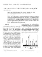
Figure 1. XRD pattern of the obtained product.
*Author for correspondence ()
Lixia Yang et al
920
Figure 2. (a) TEM image of the product, (b) EDS pattern, (c) a single nanorod of the product and (d) HRTEM image
from (c) and the inset of (c) is the corresponding SAED pattern.
2. Experimental
Hydrous ferric chloride (FeCl
3
⋅6H
2
O), hydrous tin chlo-
ride (SnCl
4
⋅5H
2
O) and sodium hydroxide (NaOH) were of
analytical grade and used as received without further puri-
fication. In a typical experimental procedure, 0⋅33 mmol
SnCl
4
and 0⋅33 mmol FeCl
3
were dissolved in 30 mL dis-
tilled water at room temperature. 10 mL 2M NaOH solu-
tion was added to the above solution and yellow-brown
precipitates occurred immediately. Then the mixture solu-
tion was transferred into a commercial stainless steel Tef-
lon-lined autoclave of 50 mL capacity. The autoclave was
maintained at a temperature of 180°C for 12 h without
stirring and shaking during heating and then was allowed
to cool to ambient temperature naturally. The products
were collected by centrifugation, washed twice with dis-
tilled water and absolute ethanol respectively, and finally
dried in air at 60°C.
The XRD pattern of prepared powder sample was col-
lected using a Rigaku D/Max-2200PC X-ray diffractometer
using CuKα radiation (λ = 1⋅54178 Å) and a graphite
monochromator. Transmission electron microscopy (TEM)
Facile hydrothermal route to the controlled synthesis of α-Fe
2
O
3
1-D nanostructures
921
Figure 3. (a, e) TEM images of the products prepared by the addition of 0⋅66 mmol SnCl
4
, (b) a single
double-shuttle of the product, (c) higher magnification of part of (b); (d) HRTEM image from (c); the
inset of (b) is the corresponding SAED pattern and (f) is the corresponding SAED pattern of (e).
Lixia Yang et al
922
and selected-area electron diffraction (SAED) were ob-
tained using a JEOL JEM-2100F field emission transmis-
sion electron microscope.
3. Results and discussion
Figure 1 shows the typical XRD pattern of the product.
All the reflections of the XRD pattern can be indexed to
the single phase of α-Fe
2
O
3
with hexagonal structure
(JCPDS Card No. 86-0550). No other phases of SnO
2
or
FeOOH were found in the XRD pattern.
The morphology of the as-prepared sample was inves-
tigated by TEM, as shown in figure 2. One can see α-
Fe
2
O
3
nanorods with diameters of ~
100 nm and lengths
up to 1 μm. Each nanowire is straight and has relatively
sharp tips at the two ends. Energy dispersive spectro-
scopy (EDS) shows that the nanorods consisted of tin,
iron and oxygen (copper came from copper grid of TEM
sample holder) (as shown in figure 2b). Selected area
electron diffraction (SAED) patterns taken from different
positions from an individual nanorod or different α-Fe
2
O
3
nanorods were essentially the same, indicating that α-
Fe
2
O
3
nanorods were single-crystalline. Figure 2c shows
a typical single nanorod and its corresponding SAED
pattern (inset of figure 2c). The SAED pattern can be
indexed as the [00-1] zone axis of hexagonal α-Fe
2
O
3
,
which is consistent with the XRD result (figure 1). Figure
2d shows the high-resolution TEM (HRTEM) micrograph
of an individual nanorod. The visible lattice fringes further
confirm that the as-obtained nanorods are single crystals.
The addition of SnCl
4
played a key role in the controlled
formation of α-Fe
2
O
3
nanorods. We carried out the experi-
ment without the use of SnCl
4
with equal amounts of
FeCl
3
and NaOH concentrations at 180°C for 12 h. Only
FeOOH nanobelts formed, which means that the introduc-
tion of SnCl
4
caused the formation of α-Fe
2
O
3
instead of
FeOOH. We also tried to increase the addition of SnCl
4
concentration to 0⋅66 mmol, and a single phase of
α-Fe
2
O
3
was still obtained, with the occurrence of Sn as
evidenced by EDS. However, the morphology of α-Fe
2
O
3
was double-shuttle as shown in figure 3, and the shuttles
have a rough surface with sawtooth structure (figure 3c).
It is amazing that SAED pattern taken along the [010]
zone axis reveals that the double-shuttles are single-
crystalline in nature. Shown in figure 3d is the corres-
ponding high-resolution transmission electron micro-
scopy (HRTEM) image and the corresponding SAED
pattern. Like the XRD profile, the HRTEM image and the
SAED pattern may also be indexed to hexagonal phase of
α-Fe
2
O
3
. The observed lattice spacings of 0⋅370 and
0⋅269 nm correspond to the (012) and (104) planes of hexa-
gonal α-Fe
2
O
3
, respectively. It is different from the pro-
duct prepared by adding 0⋅33 mmol SnCl
4
, which gives
single crystal nanorod morphology. From the sawtooth
morphology we can speculate that the formation of 1-D
nanostructure may have come from the nanoparticle
aggregation, at the same time oriented aggregation and
particle fusion may have occurred in the process since the
SAED pattern shows a single crystal diffraction pattern
and no obvious particle boundary was found from
HRTEM. In addition, the formation of double-shuttles of
α-Fe
2
O
3
nanostructures accompanied by the occurrence of
some tidy nanoparticles, are as shown in figure 3e.
The effect of SnCl
4
addition on the morphology of α-
Fe
2
O
3
is obvious, but what is the existence of Sn? it is
clear that Sn is present with the formation of α-Fe
2
O
3
phase on the basis of EDS, but XRD diffraction peaks
give no diffraction peaks of Sn or corresponding oxides.
From the corresponding SAED pattern (figure 3f) focused
on the areas of large amount of nanoparticles, one can see
the intense diffraction rings of polycrystals, which indi-
cates the formation of well-crystallized product. According
to the index calculation and the EDS result, we believe
that the nanoparticle phase was SnO
2
. Due to the low
content of SnO
2
, the diffraction peaks cannot be found in
the XRD pattern. Hence, the final products should be a
mixture of α-Fe
2
O
3
–SnO
2
, with α-Fe
2
O
3
as the main
phase. (1 – x)α-Fe
2
O
3
–xSnO
2
composite has been reported
by Sorescu et al (2004), but the morphology of α-Fe
2
O
3
was different from the present study. It is believed that
the addition of SnCl
4
has a key influence on both the
composition and morphology of the products, However,
detailed formation mechanism of α-Fe
2
O
3
nanostructures
still needs to be further studied.
4. Conclusions
In summary, we have successfully developed a facile
hydrothermal synthetic route to single-crystalline Sn-doped
α-Fe
2
O
3
nanostructure. The introduction of SnCl
4
has a
key influence on both the composition and morphology
of α-Fe
2
O
3
. The addition of SnCl
4
favours the formation
of Fe
2
O
3
rather than FeOOH, and the morphology can be
tuned from nanorod to double-shuttle as the increase of
SnCl
4
concentration. This simple method does not need
any seed, catalyst, or template, thus is promising for
large-scale and low-cost production. The method demon-
strated in this paper may also be extended to the fabrica-
tion of other doped materials.
Acknowledgements
The authors are grateful for the financial support by the
Natural Science Foundation of Ludong University ((Nos
LY20072901, L20062901, 032912, 20052901), the Youth
Science Foundation of Shandong Province (Nos 2005BS
11010), the Natural Science Foundation of Shandong
Province (Nos Q2006F05, Y2005F11), the Applied Pro-
ject of Yantai City (No. 2005227), and the Applied Pro-
Facile hydrothermal route to the controlled synthesis of α-Fe
2
O
3
1-D nanostructures
923
ject of Educational Bureau of Shandong province (Nos
j05d03, j04b02).
References
Cao M, Liu T, Gao S, Sun G, Wu X, Hu C and Wang Z L 2005
Angew. Chem. Int. Ed. 44 4197
Chen J, Xu L, Li W and Gou X 2005 Adv. Mater. 17 582
Chueh Y L, Lai M W, Liang J Q, Chou L J and Wang Z L 2006
Adv. Funct. Mater. 16 2243
Jiao F, Harrison A, Jumas J C, Chadwick A V, Kockelmann W
and Bruce P G 2006 J. Am. Chem. Soc. 128 5468
Kotsikau D, Ivanovskaya M, Orlik D and Falasconi M 2004
Sensor Actuat. B101 199
Rumyantseva M et al 2006 Sensor Actuat. B118 208
Sorescu M, Diamandescu L, Tarabasanu-Mihaila D, Teodorescu
V S and Howard B H 2004 J. Phys. Chem. Solids 65 1021
Tang B, Wang G, Zhuo L, Ge J and Cui L 2006 Inorg. Chem.
45 5196
Wu C Z, Yin P, Zhu X, Yang C O and Xie Y 2006 J. Phys.
Chem. B110 17806
Wu J J, Lee Y L, Chiang H H and Wong D K P 2006 J. Phys.
Chem. B110 18108
Zhu L P, Xiao H M, Liu X M and Fu S Y 2006 J. Mater. Chem.
16 1794