crystallographic methods and protocols
Bạn đang xem bản rút gọn của tài liệu. Xem và tải ngay bản đầy đủ của tài liệu tại đây (24.22 MB, 388 trang )
CHAPTER
1
Introduction
Mark R. Sanderson
This chapter is intended to give an overall view of the process of struc-
ture solution with some of the basic theory behind it. It is possible to skip
the most mathematical section, at any rate, on a first reading. There is a
bibliography at the end of this chapter that should provide further read-
ing matter for readers at every level of crystallographic experience.
1.1. Fundamentals
of
X-Ray Difiaction
X-rays are a form of electromagnetic radiation, with a shorter wave-
length than radio waves or visible light. X-rays are used in crystal studies
because their wavelength (1.542 x l&lo m for copper K cx radiation) is
comparable to the planar separation of atoms in a crystal lattice, if the
Bragg description of diffractron from a crystal is considered. The Ang-
strom unit, where 1 A = lo-lo m, is still widely used in diffraction circles.
Measurements in these units, rather!han their SI equivalents, can be spo-
ken in fewer syllables (e.g., 1.547 A, compared with 0. 1547 nm).
Safety: It must be stressed that X-ray equipment must under no
circumstances be used by an untrained operator. Training in its use
must be received from an experienced worker.
1.1.1. X-Ray Generation
X-rays are generated when a beam of electrons at a potential of approx
10,000 eV is accelerated from a small tungsten filament (the cathode) to
strike an anode (usually a copper target for macromolecular studies).
The deceleration of these electrons, which is known by its German name
bremsstrahlung,
causes electrons to be knocked out of the inner K and A4
From Methods in Molecular Bology, Vol 56 Crystallographx Methods and Protocols
Edlted by C Jones, 6 Mulloy, and M Sanderson Humana Press Inc , Totowa, NJ
1
2
Sanderson
0.5 1.0 1.5 2.0 2.5
Wavelength (A)
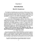
Fig. 1. X-ray spectrum of MoKa, 50 kV, and CuKa, 35 kV The absorption
spectrum of nickel is shown by the dotted lme.
atomic
shells and dissipates a large amount of heat. When the electrons
in higher levels fall back to these inner shells, emission of X-ray radia-
tlon occurs. When the transitions are from K to L, then K al and K a2
radiations are produced, whereas the transition from M to K leads to K
p 1 and K p2 radiation. Since the electrons are involved m multiple colli-
sions, these defined lines are superimposed on a background of white
radiation. Figure 1 shows a typical X-ray emission spectrum. In macro-
molecular studies, copper K a radiation is usually used with the K p
filtered out either by a graphite monochromator or by nickel filters.
Molybdenum radiation of wavelength 0.71 f\ is often used m small
organic and inorganic molecule diffraction studies, but has also been used
for several high-resolution protein data collections.
An alternative source of X-rays is synchrotron radiation, which is gen-
erated tangentially to a ring
of
accelerating electrons. This source of
X-radiation is available at various centers throughout the world, such as
the Daresbury Laboratories (Warrington, UK), Brookhaven National
Laboratories ( Long Island, NY), The Photon Factory (Japan), L.U.R.E.
(Paris, France), and the E.S.R.F. (Grenoble, France). Synchrotron radia-
tion offers the possibility of tuning the X-ray wavelength to suit the prob-
Introduction 3
lem being studied, as discussed by Krishna Murthy in Chapter 5, and it
has a beam with narrow divergence, resulting in small spot sizes, which
is a great advantage when studying viral crystals as discussed by Eliza-
beth Fry et al. in Chapter 13. The X-ray flux attainable at synchrotron
rings is also much higher than that generated in a conventional X-ray
laboratory, often allowing higher-resolution data to be collected in a
shorter time. Research groups apply for “beam time” at these centers,
travel to the synchrotron with their crystals, and collect data during then
allocated period. Two types of generators are in general use in X-ray
diffraction laboratories, known as sealed-tube generators and rotating
anode generators.
1.1.1.1.
SEALED-TUBE GENERATORS
These X-ray sources consist of a sealed evacuated glass tube contain-
ing a filament and a fixed hollow target anode, which is cooled by water.
Generators fitted with these tubes produce X-rays of up to 3 kW, corre-
sponding to a current of 50 mA and voltage of 60 kV. Heat generated by
the decelerating electrons means that these tubes cannot be operated at
very high powers since the anode will melt. The advantage of sealed-
tube generators is that they require less maintenance than the rotating
anode generators described below, and the sealed tube may easily be
replaced at the end of its lifetime. The major disadvantage of these sys-
tems is the limit on the operating power of a fixed target source, which
results in lower X-ray fluxes compared with those from rotating anode
generators.
1.1.1.2.
ROTATING ANODE GENERATORS
Rotating anode generators were developed in order to increase the
X-ray flux. The filament is mounted in a focal cup in the electron gun,
and the electron beam is directed at a rotating anode (usually copper).
The anode is spun so that a cooler region of the copper anode is continu-
ally brought into the path of the X-ray beam. This allows higher powers
to be used without melting the target. Here again, the rotating copper
wheel is water-cooled, often on an internal circuit that is heat-exchanged
against an external cooling loop. Figure 2 shows a Rigaku RU-200 X-ray
generator, with the rotating anode mounted on top of the stainless-steel
column. In this generator, X-rays can exit from two ports (to the left and
to the right), sealed by an-tight beryllmm windows, which are transpar-
ent to X-rays. In the figure, only the right-hand port is in use and has an
Sanderson
Fig. 2. Rigaku RU-200 X-ray generator with a mirror system and an R-AXIS
II image plate detector mounted against the right port (courtesy of Dr. Paul
Freemont, I.C.R.F.).
X-ray mirror system and image plate detector mounted against it (Rigaku
Raxis II, image plate detector; X-ray mirrors developed by Z. Otwinowsky
and marketed by Molecular Structure Corporation). The electron gun is
evacuated to 10M5 Pa by a turbomolecular pump, which is backed on to
an oil diffusion pump. These generators typically operate at a power of
5.4 kW when a small filament (300 pm) is used and 12 kW when a broad
focus (500 pm filament) is used. Recently, X-ray sources have become
available with more compact, high-voltage generators. The older instru-
ments have oil immersed high-voltage tanks, which take up much more
floor space, an important consideration when laboratory space is limiting.
1.2. Crystals and Symmetry
A crystal may be thought of as a three-dimensional lattice of mol-
ecules. An early study of crystal morphology of quartz in 1669 by a Dan-
ish physician, Nicolaus Steno, concluded that the angles between similar
crystal faces were the same. At the end of the 18th century, Abbk Hauy
Introduction
5
and Romk de 1’Isle extended these observations to other crystals, and
found that the interfacial angles were the same even though the overall
morphology of the crystals may be very different. Bravais showed that
symmetry criteria limited the number of lattices to the 14 lattices shown
in Fig. 2 of Chapter 3. It was known even before the discovery of X-rays,
through the mathematical studies of Federov in Russia, Schoenflies in
Germany, and Barlow m Britain at the turn of the century, that there 1s
only a finite number of ways of arranging objects symmetrically wlthin a
crystal lattice. This gives rise to the 230 possible space groups, which are
listed in
International Tables for Crystallography,
published by Rediel
NEKluwer Academic Publishers, Norwell, MA. A copy of these tables
should be available to anyone wishing to work in crystallography.
For biological studies, we need only consider 65 out of the 230 pos-
sible space groups, because macromolecules are chiral and therefore only
those space groups lacking a center of symmetry need be considered.
The subject of crystal symmetry is discussed more fully in Chapter 3.
1.2.1. Miller Indices
The crystal may be thought of as sectioned into planes as shown below
(Fig. 3). Miller indices are the three intercepts that a plane makes with
the cell axes, in units of the cell edge. For example, if the plane intersects
the axes of a cell with lengths
a,
b, and c at coordinates
a’,
b’, and c’, then the
Miller indices are given by
h
=
a/a’, k
=
b/b’
and I = c/c’.
1.2.2. Diffraction from Lattices
The crystal may be viewed, by analogy with the difiaction of visible light,
as a three-dimensional grating, with the diffracted rays interfering in phase and
out of phase to produce a diffraction pattern. The spacing of the resulting pat-
tern is inversely proportional to the lattice spacing as given by Bragg’s law:
nh = 2dsm 8
(1)
where h = wavelength, 6 = diffraction angle,
d
= lattice spacing, and
n
= dif-
fraction order. Figure 4 shows the derivation of Bragg’s law. Two incident
rays are shown with a path difference given by
A(path) = PQ + QR = nh.
1.2.3. Resolution
Having crystals that diffract X-rays to large values of 8 IS vital to being
able to solve a structure so that biological detail may be extracted. When
a crystallographer is found talking about a new crystal form diffracting
to the edge of the film (on a precession camera with a crystal-to-film
6
Sanderson
b’,
a’
a
A
010
iii
b
l l -
C
t.
b
a
C
@
110
Fig. 3. Miller indices of lattice planes wlthin a crystal. (A) A Lattice plane
with intercepts
a’, b’,
and c’ along the
a, b,
and c axes. (B) Lattice planes m a
two-dimensional lattice. (C) Lattice planes m a three-dimenslonal lattice.
(Reproduced with perrmssion from ref. I.)
distance of 10 cm), this is often a cause for celebration, since the data
once collected and processed from this crystal form will allow the
polypeptide backbone to be traced (for a protein) or unambiguous posi-
tioning of the backbone and bases (for a nucleic acid). Equation 1 may be
rearranged as d = h/2 sin 8, since we are considering first-order diffrac-
tion with YI = 1. Substituting for the diffracting angle 0 gives the useful
form of the equation
d
= h/2 sin [( 1/2)tan-’ (r/F)] where r is the distance
of a diffraction intensity from the center of the film and F is the crystal-
Introduction 7
82 + 83 =nh
(4
I% = O’R = d srn 0
04
Substltutlng (b) Into (a) gwes
2dslnO=nh
Fig. 4. The derivation of Bragg’s law.
to-film distance (10 cm for many precession cameras). Further details of
preliminary crystal characterization are discussed in Chapter 3 by Sherm
Abdel-Meguid et al. Figure 5 shows the diffraction pattern from a crystal
of the thymidme kmase from herpes simplex vn-us type 1, which has
been mounted together with a small amount of buffer in an X-ray capil-
lary tube (Fig. 6) and irradiated with X-rays. Since water is an integral
part of the crystal lattice, crystals must be mounted and kept hydrated, a
very important observation first made by Hodgkin and Bernal (2). Flash-
freezing crystals to liquid nitrogen temperatures may also be used to
maintain the lattice hydration as described in Chapter 3. The reflections
recorded in this 2” oscillation photograph may be assigned indices
h, k,
and
1
and their intensities
I(hkl)
measured by using integration software.
The photograph shows a distorted picture of the reciprocal lattice. In the
past, precession X-ray cameras were used to give an undistorted view of
the reciprocal lattice, which facilitated space group assignment, and
indexing of the reflections, when this was done by hand.
1.3. An Overview
of Macromolecular Crystal Structure Solution
This section shall give a brief nonmathematical overview of macro-
molecular structure solution, leaving a more detailed treatment for later
m the chapter (Section 1.4.).
8
Sanderson
Fig. 5. Diffraction of thymidine kinase from herpes simplex virus type 1
recorded on an MAR image plate detector. (M. R. Sanderson and W. C. Sum-
mers, unpublished results.)
1.3.1. Stage 1: Protein Preparation and Crystal Growing
1.
The first stage in a crystallographic study is to obtain tens of milligrams of
the macromolecule (or macromolecules when the structure of a complex is
being undertaken) in a very pure form, either from:
a. A natural source rich in the protein;
b. The use of cloning techniques to engineer a vector that will overexpress
the desired macromolecule in large amounts; or
c. Chemical methods, as in the case of DNA synthesis for DNA
crystallization.
Chapter 2 covers aspects of genetic engineering. Biochemical tech-
niques are used to purify the macromolecule; this can usually be achieved
in fewer steps with cloned material. An affinity “tag” is often attached in
order to aid purification, although cleaving the tag away from the molecule
Introduction
I 3g. 6. Crystal of thymidine kinase mounted in a glass capillary tube
atta ched to a goniometer head using plasticine. The arcs and sledges on
wn
nometer head allow the crystal to be centered in the X-ray beam.
and
the
of interest may introduce heterogeneity, which hampers crystallization.
The knowledge of solubility in different buffer solutions at different salt
concentrations gained by biochemical manipulation of the protein can often
be very useful when crystallizations are set up.
10 Sander-son
2. Crystalhzatron of protems IS discussed in Chapter 2, of DNA and protem-
DNA complexes m Chapter 12, and for membrane protems m Chapter 14
1.3.2. Stage 2: Symmetry Determination
The symmetry of the macromolecular crystals is determined as dis-
cussed in Chapter 2. If the crystals are found to be sensitive to radiation
damage in initial experiments, then cooling techniques, also discussed m
Chapter 2, may be used to extend the crystal lifetime. Macromolecular
crystals are formed of molecules that are chiral, so only the 65 space
groups that lack a center of symmetry need be considered.
1.
2
3
4.
1.3.3. Stage 3: The Strategy for Structure Solution
The strategy for structure solutton wrll depend on whether or not a stmrlar
macromolecule, or fragment of it, has been solved before, and the coordr-
nates are avatlable.
If coordmates are obtainable, then the structure may be solved by molecular
replacement usmg the phase mformatton from the prevrously solved struc-
ture, and only a natrve X-ray diffraction data set needs to be collected. “Natrve
data” are crystallographlcjargon describing data collected from crystals m
then native state, unmodtfied by, for example, heavy-atom dertvatizatton
If a structurally related macromolecule has not been solved, then the phase
mformation has to be obtained
“de
~OVO ” from either several heavy atom
derrvatrves with the technique of multiple isomorphous replacement (MIR,
descrrbed m Chapter 6), or by using a smgle heavy-atom derrvatrve and the
multiple wavelength methods covered m Chapter 5
Once native X-ray diffraction data and phase mforrnatton are available,
then the electron density map is calculated and the chemical structure of
the macromolecule fitted mto the electron density map using a computer
graphics system, and refinement may begin. In refinement, the best fit
between the X-ray dtffraction data and the fitted model IS achieved
computatronally, etther using the more traditional techmque of conlugate
gradtent energy mimmrzatton dtscussed m Chapter 9 by Eric Westhof and
Phtlhppe Dumas, or by using the recent technique of molecular dynamtcs
discussed m Chapter 10 by Axe1 Brunger.
1.4. Diffraction Theory
This section shall discuss diffraction theory. The reader may wish to
skip this section on a first reading.
Most crystallographic computer programs use as input the structure
factor amplitudes
Fhkl.
These structure factor amplitudes are proportronal
to the square roots of the intensities (I), 1
Fhkl 1 = @&&TJ
where
L IS
Introduction 11
the Lorentz correction, which is dependent on the geometry of the cam-
era used to collect the data and arises because the different reflections
spend varying times in a reflecting position dependent on their location
within reciprocal space and their angle of approach to the reflecting posi-
tion. The constantp 1s a correction for the polarization that X-rays expe-
rience on reflecting from a crystal. The component of the electric vector
parallel to the crystal plane will only be affected by the electron density
parallel with the plane, whereas the electric vector perpendicular to the
plane will be dependent on electron density in the vertical plane and on
the incident angle. The remaining constant k IS dependent on beam inten-
sity, crystal size, and other fundamental constants. Its use is avoided by
using a relative F, with 1 F,el 1 = c 1 Fobs 1 = m
where
Fohp IS the
observed
F
and is scaled relative to
F,,,
at the refinement stage, once the
structure is determined, and a calculated value of
F
has been derived by
back-transformation of the structure model.
The final objective during crystal structure solutron is the calculation
of an electron density map so that the atomic model may be fitted into it.
In order to calculate the electron density, both the amplitudes and phases
of the reflections must be known. Since only the square of the amplitude
of the waves is recorded, the phase information is lost. The regaining of
phase mformation (known in crystallography as the Phase Problem) is
therefore central to structure solution and is discussed below.
The total scattering by the crystal IS given by the rat10 of the sum of the atomtc
scattering amplitudes of the atoms in the lattice to the scatterrng by a point elec-
tron at the origin. For N atoms, the structure factor is defined by Eq. (2).
y=asm(otfkx)
(3)
where s is the scattering vector and rJ is the position vector of the jth
atom and is given by Eq. (4) in terms of fractional atomic coordinates.
q=xja+yJb=zJc
(4)
The structure factor equation is similar to the wave equation (Eq. 3) encoun-
tered in physics in having an amplitude term a and a phase term (ot f AZ). For
an explanation of dot (scalar) r/ s and cross (vector) products, and the vector
notation and Fourier transforms given below, the reader IS referred to one of
the number of excellent mathematical texts listed at the end of this chapter.
12
Sander-son
The reciprocal lattice vector Ghkl
is defined by Eq. (5) in terms of the
lattice planes of the real lattice;
hkl
are the reflection indices:
Ghk, = ha* + kb” + lc*
(5)
where a*, b*, and c* are base vectors in reciprocal space related to the
real space vectors a, 6, and c for a right handed system:
a* =
&,b*=s,c*=s
(6)
Equation 7 defines the scattering vector with respect to the reciprocal
lattice vector:
s = 2xGhk,
(7)
An expression for the scalar or dot product r, * s may be derived by sub-
stituting Eqs. (4) and (5) into Eq. (7):
r, * s = 2~c(x,a + yJb + z]c) * (ha* + kb* + Ic*) = 27c(hx, + ky, + lz,)
(8)
Substituting this expression into Eq. (3) gives an alternative expression
for Eq. (3) in terms of fractional atomic coordinates and Miller indices:
Fhk/ 7 ;, .@xP 2dhxJ + ‘b’, + lz,)
(9)
The form of the scattering vector is complex, and hence, may be resolved
into real and imaginary components:
Fhkl = Ahkr + lBhk1
(10)
A/,k, =/ ;, @OS27Lr, S
(11)
Bhk, ;=; @n2nr, * S
The phase angle may be given as
(12)
dhkl = tan-‘(BhkllAhkl)
(13)
1.4.1. Electron Density
If one imagines the crystal divrded up into small volumes
dv
with point
charges where p is the electron density distribution, then an expression
for the total scattering amplitude is:
F(s) = J
p(r)exp (2rcis * r)dv
(14)
Introduction
13
The interesting expressron for X-ray crystallography is Eq. (15), the
inverse transform of Eq. (14), since we are interested in solving the struc-
ture by calculating its electron density.
p(r) =J F(s)exp
(-2nu
* r)dv*
(15)
Equation 16 is used for computing the electron density:
(16)
If Friedel’s law [I
(h,k,l)
= I
(-h, -k,
-1)] holds, then Eq. (16) above sim-
plifies to:
The theory of diffraction is covered in greater depth in a number of
excellent texts, some of which are listed in the bibliography.
1.4.2. Phasing the Macromolecular Structure
1.4.2.1.
THE PHASE
PROBLEM
As discussed above, in order to compute an electron density map, the
phase information must be recovered. A solution to this problem for
macromolecular crystallography was achieved by Max Perutz and
coworkers (3), who showed that if heavy atoms (such as mercury m a
compound, which may bind to a cysteine group m a protein) were soaked
into the crystal lattice, and they bound to the protein without disturbing
the crystal cell dimensions, then the positions of these heavy atoms may
be used to regain phase information. Figure 7 shows the perturbation of
amplitude and phase induced in a hypothetical triangular molecule on
binding a heavy-atom compound. Data from such crystals are called
“heavy-atom derivative data” or simply “derivative data” by crystallog-
raphers. The technique for structure solution using heavy atom deriva-
tives is known as multiple isomorphous replacement (MIR). In order to
overcome the phase ambiguity, the heavy-atom positions for two or more
heavy-atom derivatives are used to determine the phase. In practice, the
more derivatives that can be used, the better, since the overall phase may
be calculated with greater certainty. Chapter 6 provides a full discussion
of phasing using heavy-atom derivatives. Chapter 5 discusses the use of the
anomalous contribution with the isomorphous contribution to calculate
Sanderson
EH, Scattering by protein and heavy atom H1
EHp
SCat’terlng
by protein and heavy atom H2
Fig 7 Wave
diffracted by triangle of atoms representing a protein. (A) Scat-
tering by the protein alone. (B) and (C) Changes in amplitude and phase of
diffracted wave caused by the heavy atoms Hl and H2 (Reproduced with per-
mission from Protein Structure by Max Perutz.)
phases using only one derivative. The first stage in this phasing process
is being able to locate the heavy-atom positions, which may be achieved
by either calculating a Patterson map based on the difference between
the derivative and native data or by usmg Direct methods on this differ-
ence data.
A very active area of research is the development of techniques to
phase structures directly from the intensity data using probabilistic
methods. This area has been pioneered primarily by Brtcogne (4-6).
Gtlmore and Bricogne have now written a program based on these
methods called MICE (7). Structure solution for small organic and
inorganic molecules directly from intensity data is now routine. The
problem for macromolecules is much more difficult, since crystals of
macromolecules do not diffract to atomic resolution. Direct methods
techniques cannot therefore be used to phase macromolecular data at
present, though in the future this may become possible using probabi-
listic methods.
Introduction
15
1.4.2.2.
THE PATTERSON METHOD
Patterson developed this method in 1934 initially to locate heavy-atom
positions in small organic and inorganic molecules, so that their posi-
tions may be used m phasing these structures, He derived an equation
(8), now named the Patterson function, using as coefficients the phaseless
square of the structure factor amplitudes:
P(r) = I/vhs ) Fhkl I2 exp (-27cih r)
(18)
where
h
= Ghkl is the reciprocal lattice vector. Since 1
Fhkl I2 = lFA~ 12,
the
Patterson is a real expression and may be expressed as:
P(r)= l/v$ Fhkl 12cos (-2nzh r)
(19)
Using convolution theory and Fourier transformatron, the expression m
terms of electron density is:
The Patterson function has the following important features:
1. There are N2 - N nonorigm peaks in a calculated map, so peak overlap
makes the Patterson map hard to interpret.
2. The distance of the peaks from the ortgm 1s the mteratomtc vectors between
the zth andjth atoms (r, -Y,).
3. The heights of the peaks m the Patterson are proportional to the products
of the atomic weights of the ith andjth atoms Z&
4. Space group symmetry Introduces simplification mto Patterson mterpreta-
tion. For example, in space group P2,, the vectors between general equiva-
lent positions X, y, z and X, 0.5 + y,-Z produces the Harker section (2x, 0.5,
22) with all the vectors of this type m the plane y = 0.5.
The Patterson vectors u, v, w of the peaks high in the peak height hst-
ing are analyzed for correspondence with the Harker vectors derived from
the crystal space group. This latter analysis is often called “hand solutron.”
The Patterson technique has now been widely applied to protein dif-
ference data in order to locate the heavy-atom positions within a macro-
molecular crystal. The differences
(Fden,,
-
Fnatrve)
are calculated for
derivative and for the native protein, once they have been scaled together.
If one takes the case of a protein soaked in a mercury compound, one
16 Sanderson
may think of the difference data as containing only the contribution from
the mercury atom, since the contrrbution from the protem has been
removed by taking the difference. In order for this to be true, the deriva-
tive data must be very well scaled against the native; time spent making
sure this is true often pays dividends. An example of the difference
Patterson map for an osmmm derivative of the porcine growth hormone
is given in Chapter 6.
In addition to solving the difference Patterson by hand as described
above, a range of software is now available, such as HASSP (9) written
by Terwilleger et al. and RSPS by Knight, which is integrated into the
CCP4 package. These programs take as input (Fdenv - Fnatl,,J and will
solve the Patterson map automatically. It is advisable to check the auto-
matic solution against the hand solution, and to compare these results
with those determined from Direct methods. Fmally, crossdifference
Fourier maps calculated using phases determined from one heavy-atom
derivative should solve the positions of other heavy-atom derivatives.
Finally, the positions determined by Patterson and Direct methods and
crossdifference Fourier maps should be self-consistent.
1.4.3. Direct Methods
Direct methods are used routinely for solving small organic/inorganic
structures and are based on the inequahty and probability relationships
between structure factors that arise from the impossibihty of negative
electron density.
Because of the fact that the structure factor Fhkr is dependent on sine/h and
space group symmetry, normalized structure factors
Eh
with these contri-
butions removed are used in inequality and probability relationships.
1 E/,1 =
IFhi
&
(21)
where
h
=
hkl,
and E is a term that varies for certain groups of reflections
in given space groups (these conditions are tabulated in International
tables). For the case of solvmg heavy-atom positions within a protein, it is
the scaled structure factor differences (FdenV - F,,,,,,) that are normal-
ized; the Wilson plot from the normalization routine should be lmear. If
it is not, this may be because of poor scaling and may result m failure to
obtain a Direct methods solution. In order to solve the heavy-atom posi-
Introduction 17
tions in derivatives of macromolecules, one needs only to consider the noncen-
trosymmetric space groups, discussion will be limited to these. For reflec-
tions in noncentrosymmetric space groups, a phase angle can take any value
from 0 to 2rc. Once origin and enantiomorph reflections have been defined, it
is then possible to build up a “tree” of phased reflections from this starting
set by using the expression in an equation known as the C2 relationship:
(22)
where the parentheses represent summation over reciprocal space. SHELXS
(10) and MLJLTAN 80 (11) are the Direct methods programs generally used,
and these will automatically select starting reflections and use the C2 rela-
tionship with each reflection being given a phase value of (n/4,37c/4,5n/4,
7x/4) in turn. The phases are then refined by the weighted tangent formula:
(tanh) = FWkwh -k 1 EkEh -k 1 sin (ok + $h -k>
TWkWh-kl EkEh-ki cos (ok+ oh-k)
(23)
where wh = tanh [(oh)/21 and ah = WI/2 1 EhEkEh -k I. ah is a test for the
validity of a phase and N is the number of atoms in a unit cell.
The programs analyze the probability that a given starting phase
set gives rise to a correct solution on the basis of several figures of merit
criteria, and then calculate and peak-pick Fourier maps for the highest
ranked solutions. The solution to the heavy-atom positions often corre-
sponds to the highest peaks within this map (12).
1.4.4. Multiple Isomorphous Replacement
Once the positions of the heavy atoms have been located, the phases abest
determined from them may then be used to calculate the electron density map
using Eq. (24), where m is the figure of merit, as discussed fully m Chapter 6:
p(r) = CmF,exp 1 ia~est 1
exp (-2&s * r)
(24)
In the case of a protein, the amino acid sequence is then fitted into the
electron density map using a graphics program, such as 0 (13,14), and
the structure refined as discussed in Chapters 9 and 10.
Acknowledgments
I thank all the authors for their contributions and all the subsequent
revisions. I thank Drs. Max Perutz and Don Crothers for permission to
reproduce figures from their books, and Kate Kerwin and Mark Simon
for photographic and graphical work.
18 Sander-son
References
1 Etsenberg, D and Crothers, D (1979) Physzcal Chemistry wzth Appllcatlons to the
Lzfe Sciences, BenJamm-Cummmgs, Redwood Ctty, CA
2 Bernal, J. D and Crowfoot, D (1934) Use of the centrtmge m determmmg the
denstty of small crystals. Nature 134, 809,8 10
3 Green, D. W Ingram, V M , and Perutz, M F (1954) The structure of haemoglobm
IV Sign determination by the isomorphous replacement method Proc Roy Sot
A225,287-307
4 Brtcogne, G (1984) Maximum entropy and the foundattons of Direct methods
Acta Cryst A40,410-445
5 Bricogne, G. (1988) A Bayestan stattsttcal theory of the phase problem I A mul-
ttchannel maximum-entropy formahsm for constructmg generahzedJomt probabtl-
tty dlstributtons of structure factors Acta Cryst A44, 5 17-545
6 Brrcogne, G (1991) Maximum entropy as a common statistical basis for all phase
determmation methods, m Crystallographic Computmg 5 (Moras, D , PodJarny,
A D , and Threrry, J C , eds ), Oxford Umversity Press, Oxford, UK
7. Gllmore, C J and Bricogne, G. (1991) Maxtmun entropy, hkehhood, and the phase
problem m single crystal and powder diffraction, m Crystallographzc Computmg 5
(Moras, D., PodJamy, A D , and Threrry, J C., eds.), Oxford University Press, Oxford, UK
8 Patterson, A L (1935) A direct method for the determmatlon of the components of
mteratomlc distances m crystals. 2 Krzst 90,5 17-542
9 Terwtlhger, T. C , Kim, S -H , and Elsenberg, D. (1987) Generalized method of
determmmg heavy-atom posntons using the dtfference Patterson function Acta
Cryst A43, l-5
10 Sheldrtck, G M (1990) Phase annealing m SHELX-90, Direct methods for larger
structures Acta Cryst A46,467-473
11 Germam, G., Main, P , and Woolfson, M M (1971) The apphcatton of phase rela-
ttonships to complex structures III The optimum use of phase relationshtps Acta
Cryst A21,410-445
12 Sheldrtck, G M (1991) Chapter 13, in Crystalfographzc Computrng 5 (Moras, D ,
Podjarny, A D., and Thterry, J C , eds.), Oxford Umversny Press, Oxford, UK
13 Jones, T A , Zou, J -Y , Cowan, S W , and KJeldegaard, M. (1991) Improved
methods for butldmg protem models m electron denstty maps and the locatton of
errors m these models Acta Cryst A47, 1 l&l 19
14 Jones, T. A and KJeldegaard, M. (1994) Chapter 1, m From Fzrst Map to Fznal
Model (Bailey, S , Hubbard, R , and Waller, D , eds ), CCP4 Workgroup
Bibliography
Mathematical Texts
A&en, G (1970) Mathematxal Methods for Physusts Academic, New York
Bamberg, P and Sternberg, S (199 1) A Course zn Mathematzcsfor Students ofPhyszcs,
vols 1 and 2 Cambridge Umversny Press, New York.
Boas, M L (1983) Mathematzcal Methodsfor the Physzcal Sczences Wiley, New York
DuChateau, P C (1992) Advanced Math fir Physzczsts and Engzneers Harper Collms
outline series, Harper Collms, New York
Introduction
19
Fltts, D. D. (1974) Vector Analysis rn Chemzstry McGraw Hill, New York.
Hurst, D M (1994) Mathematzcs for Chemzsts Macmdlan, New York. (This covers
vector manipulatton and Founer transformation and is parttcularly recommended
as an mtroductton )
Janm, J. (1985) Chapter 5, m Methodes Btophystquespour l’etude des Macromolecules,
Hermann, Parts
Margeneau, H. and Murphy, G M (196 1) The Mathematzcs ofPhyszcs and Chemtstry
van Nostrand, Princeton, NJ
Prince, E (1994) Mathematical Technzques in Crystallography and Maternal Sctence,
2nd ed , Springer Verlag, New York.
Stephenson, G. (1979) Mathemattcal Methodsfor Sctence Students, 2nd ed., Longman,
London.
Stephenson, G. (1985) Worked Examples in Mathemattcs for Sctenttsts and Engineers.
Longman, London
Books on Crystallography
Some of the older books give a very clear introductton to the SubJect Unfortunately
many of these are out of print and may only be obtainable from libraries
Basic Introductions
Dressier, D. and Potter, H (1991) Dzscoverzng Enzymes W H Freeman, New York.
Matthew, C. K and van Holde, K E (1990) Bzochemutry, Beqamin-Cummings,
Redwood City, CA
Stryer, L (1995) Bzochemtstry, 4th ed , W H Freeman, New York
Short Introductions
to X-Ray Structure Determination
Branden, C -1 and Tooze, J (1991) Chapter 17, in Introductton to Protezn Structure,
Garland, New York
Cantor, C R and Schmunel, P. R. (1980) Part II of Bzaphystcal Chemutry, W. H
Freeman, New York
Etsenberg, D. and Crothers, D (1979) Chapters 16 and 17, m Physzcal Chemzstry wzth
Applzcations to the Life Sczences
Benjamin-Cummmgs Pubhshmg Company, Red-
wood City, CA. (Contains clear descrtptton of X-ray diffraction, which mcludes
mterestmg short btographtes of J D Bernal and J -B J Fourter.)
Holmes, K C and Blow, D M (1965) Methods of Btochemzcal Analysts, vol 13,
Wiley, New York, 113-239
Janm, J. (1985) Chapters 1-4, m Methodes Btophyszques pour 1 ‘etude des Macromol-
ecules. Hermann, Paris (This is a very good introduction for the French reader )
Peru@ M. (1992) Chapter 1 and Appendix 1, in Protein Structure, New Approaches to
Dtsease and Therapy. W. H. Freeman, New York.
Sawyer, L and Turner, M A (1992) Chapter 12, in Crystalltzatzon of Nucleic Actds
and Protezns (Ducrutx, A and Getge, R., eds ), IRL, New York
Stuart, D. and Jones, Y (1993) Chapter 9, in Protean Engzneering (Sternberg, M , ed ),
IRL, New York.
van Holde, E (1985) Physxal Btochemzstry, 2nd ed , Prentice-Hall, Englewood
Chffs, NJ
20
Sander-son
Texts on X-Ray Structure Determination
Blundell, T B and Johnson, L H (1976) Protein Crystallography Academtc, New
York (This IS an excellent, mdtspenstble guide to the subJect, although the
data
collectton sections are now dated )
Buerger, M J (1959) Vector Space Wtley, New York
Buerger, M J (1976) Contemporary Crystallography McGraw Hdl, New York
Bunn, C W (1961) Chemzcal Crystallography, 2nd ed., Oxford Umverstty Press,
New York
Drenth, J (1994) The Prmcrples of Protein X-ray Crystallography Sprmger-Verlag,
New York.
Dumtz, J D (1979) X-ray Analyszs and the’structure’of Organic Molecules Cornell
Umverstty Press, Ithaca, N Y (This is a thorough treatment of small molecule
crystallography )
Gtaccovazzo, C , Monaco, H L , and Vrterbo, B (1992) Fundamentals of Crystallog-
raphy Oxford Umverslty Press, New York
Glazer, A M (1987) The Structure of Crystals, Adam Htlger, Brtstol, UK
Glusker, J P and Trueblood, K N (1985) Crystal Structure Analyszs, A Primer, 2nd
ed , Oxford Umverstty Press
Ladd and Palmer, R (1989) X-ray structure determmatlon A Practical Guide, 2nd ed ,
Wiley, New York (Thts IS a very good on symmetry and space group dertvattons,
covers both small-molecule and macromolecular crystallography )
Ltfson, H and Taylor, C A (1958) Fourier Transforms andX-ray Diffraction G Bell,
London
Ltpson, H S. (1970) Crystals andX-rays Wykeham Pubhcattons Ltd , London (Thts 1s
a clear elementary mtroductton )
Ltpson, H and Cochran, W (1957) The Determznatlon of Crystal Structures G Bell,
London
McRee, D E (1993) Practzcal Protem Crystallography Academic, New York
Rhodes, C (1993) Crystallography Made Crystal Clear A Guide for Users of Macro-
molecular Models Academtc, New York.
Sherwood, D. (1976) Crystals, X-rays and Proteins Wiley, New York (Thts is a very
understandable treatment, which denves all the mathemattcal aspects of the subJect )
Stout, G H and Jensen, L H. (1989) X-ray Crystal Structure Determmatlon, 2nd ed
Wdey, New York (Thts provtdes good coverage of the basics of X-ray crystallog-
raphy, primarily from a small-molecule perspecttve )
Wtlson, H R (1966) Drffractzon of X-rays by Protems, Nucleuz Acids, and Vwuses
Edward Arnold, London. (Thts gtves a descrtptlon of dtffractlon and espectally of
hehcal dtffractton by a member of the King’s College DNA group.)
Woolfson, M M. (1978) An Zntroductlon to X-ray Crystallography Cambridge Um-
verstty Press, Cambridge, UK, (This develops dtffractton theory from a scattering
theory perspective, rather than starting with the Bragg equation. It IS an excellent
treatment of Direct methods by a leader m the field and recommended for readers
stronger m physics )
Woolfson, M M (196 1) Direct Methods m Crystallography, Oxford Umverstty Press,
New York
Introduction
21
Advanced Texts
Dodson, G , Glusker, J P , and Sayre, D (eds.) (198 1) Structural Studzes on Molecules
of
Bzologzcal Interest Oxford University Press, New York
Moras, D., PodJamy, A. D , and Thterry, J. C. (eds ) (1991) Crystallographzc Comput-
zng 5 Oxford University Press, New York (This 1s an extensive series of articles
on all aspects of macromolecular structure solutton )
Rollett, J. S. (1965) Computzng Methods zn Crystallography Pergamon Press, Oxford
Rossman, M G. (ed.) (1972) The Molecular Replacement Method Gordon and Breach,
New York
Wyckoff, H. W , Hers, C H W , and Ttmasheff, S N (eds.) (1985) Dzffractzon Meth-
ods
for
Bzologzcal Macromolecules, Methods zn Enzymology, ~01s. 114 and 1 15
Academic, New York
CCP4 Weekend Workshops
The contrtbuttons to these workshops (whtch are orgamzed by the CCP4 Workgroup)
are written up and circulated to the parttctpants They provide an mvaluable source of
up-to-date methods and apphcattons Below are listed the titles since 1987
Helltwell, J R , Machm, P A, and Paptz, M Z (1987) Computational Aspects of
Protein Crystal Data Analysts
Bailey, S , Dodson, E , and Phtlhps, S (1988) Improvmg Protein Phases
Goodfellow, J , Hendrick, K., and Hubbard, R (1989) Molecular Stmulatton and Pro-
tein Crystallography
Hendrick, K , Moss, D S , and Tickle, I J (1990) Accuracy and Reltabtlny of Macro-
molecular Crystal Structures
Wolf, W , Evans, P R , and Leslie, A G. W (1991) Isomorphous Replacement and
Anomalous Scattermg
Dodson, E J , Gover, S , and Wolf, W. (1992) Molecular Replacement
Sawyer, L., Isaacs, N , and Bailey, S (1993) Data Collection and Processing
Bailey, S , Hubbard, R , and Walter, D (1994) From First Map to Fmal Model
Computer Packages
for Macromolecular Structure Solution
Information on crystallographic software is obtainable on the World Wade Web
address http.//www.un~ge.chlcrystal/w3vlc/crystal index html
Software
CCP4
Phases
Protein
X-plor
Xtal
Source
SERC Daresbury Laboratones, Warrington, Cheshire WD4 4AD, UK
B11l Furey, VA Medical Centre, Pittsburgh, PA
Wolfgang Stetgemann, Max Planck Instttut fur Btochtmte, Martmsreld,
Germany
Axe1 Brunger, Department of Molelcular Biophysics and Biochemistry,
Yale Umverstty, CT 065 11
S Hall, Crystallographtc Centre, Umverstty of Western Australia,
Nedlands 6009, Australia
Overexpression, Isolation,
and Crystallization of Proteins
Jane I? Skelly and C. Bernadette Madden
1. Introduction
Rapid developments in recombinant technology have made it possible
to overproduce selected proteins of specific interest to the levels required
for structural analysis by X-ray crystallography. High-level gene expres-
sion has facilitated the purification of many proteins that are normally
only expressed at low concentrations, as well as those that have proven
difficult to purify to homogeneity from natural sources. Furthermore,
advances in oligonucleotide site-directed mutagenesis have enabled pro-
teins to be engineered so as to possess certain features that may confer
stability or assist in then isolation. There are several examples of pro-
teins that, despite rigorous purification from their natural source, have
defied crystallization attempts, e.g., human growth hormone, but have
been successfully crystallized from recombinant sources (I). The lack of
posttranslational processing in bacterial expressed proteins can often be
an advantage to the crystallographer where microheterogeneity presents
a problem. Indeed, certain features or residues of a protein that are believed
to impede crystal formation by preventing a close-packing arrangement
may be successfully deleted by genetic manipulation without destroying
its essential functionality (2).
2. Overexpression
Many factors influence the selection of an appropriate expression sys-
tem for providing a protein suitable for structural studies. Probably the
From Methods m Molecular EOology, Vol. 56 Crystallographrc Methods and Protocols
Edlted by C Jones, B Mulloy, and M Sanderson Humana Press Inc , Totowa, NJ
23
Skelly and Madden
simplest and least expensive method for production is in bacteria, usually
Escherichia coli,
but if the protein requires further processing for its sta-
bility and acttvrty, then rt may be necessary to select a eukaryottc based
system. These include yeast, fungi, insect, and mammalian cells. Other fac-
tors to be considered include protein size, the presence of disulfide bonds,
and whether the foreign gene product is likely to be toxic to the host cell.
The methodology for the overexpression of recombinant genes is ever-
expanding. It is possible here merely to provide a limited overview of
some of the expression systems at our disposal together with a brief
rationale as to their selection. It 1s assumed throughout this discussion
that the gene coding for the protein to be overproduced has already been
cloned. For detailed laboratory protocols, see Sambrook et al (3)
2.1. Over-expression in
E. coli
An understanding of the genetics of
E. coli
has enabled the design and
construction of expression vectors and selection of host strains to achieve
the maximum possible expression of virtually any cloned gene. The
E
toll promoter sequence that provides the signal for transcrtption, i.e.,
recogmtton by the o factor of RNA polymerase, consists of two consen-
sus sequences situated some -10 and -35 bases upstream from the mttia-
tion codon. Expression vectors based on
E coli
are designed to contain a
promoter region supplied by the upstream region of an appropriate
E
colz gene. This is sited before a unique restrtctton site mto whtch the
gene to be expressed may be inserted. The new gene is then placed under
the control of the
E coli
promoter. Minor differences between the con-
sensus promoter sequences are effective in determining the level of tran-
scription of the gene, i.e., the frequency with which RNA polymerase
initiates transcrrptron. The most effective way to maximize transcription
is to locate the gene downstream from a strong regulatable promoter. A
number of plasmid vectors contaming such strong promoters have been
designed for use with suitable host strains (4-6).
Levels of expressed gene product are normally measured as a percent-
age of the total soluble cell protein. This can vary widely from cl% to
>50% depending on several factors, including:
1. The vector-host system used;
2 The stability of the mRNA;
3 The stability of the expressed gene product,
4. The possible adverse effects of the accumulated product on the host; and
5. The conditions of fermentation and induction, as detailed for each vector.
Crystallization
of
Proteins
25
Some examples of the more frequently used E.
coli
promoters are
given below.
2.1.1. The
lac
Operon
The
fat
operon is probably the best example of regulatory gene
expression in bacteria (7) and has therefore been extensively used in the
construction of expression vectors It has the disadvantage of requiring a
chemical inducer, which can be prohibitively expensive if used for large-
scale fermentation. The
lac
promoter contains the sequence that controls
transcription of the 1acZ gene coding for P-galactosidase, one of the
enzymes that converts lactose to glucose and galactose. It also controls
transcription of lacZ’, which codes for an a-peptide fragment of the same
enzyme. Certain strains of
E. coli
that lack this fragment are only able to
synthesize a functional P-galactosidase enzyme when harboring vectors
carrying the 1acZ’ sequence, e.g., pUC and M13. This can be used advan-
tageously as a means of selecting for recombinants. The lac promoter is
induced by either allolactose, a naturally occurring isomeric form of lac-
tose, or isopropyl P-o-thtogalactoside (IPTG), a nondegradable substrate,
at a concentration of ~1 mA4 in the growth medium.
2.1.2. The
trp
Promoter
The
trp
promoter is located upstream of several genes coding for
enzymes responsible for the biosynthesis of tryptophan. The
trp
promoter
is repressed in the presence of tryptophan, but induced by either 3-
mdolylacetic acid or the absence of tryptophan in the growth medium (in
a defined minimal medium, such as M9CA). A series of plasmids con-
taming the
trp
promoter have been described (8,9).
2.1.3. The
tat
Promoter
The
tat
promoter, a synthetic hybrid containing the -35 sequence
derived from the
trp
promoter and -10 from
Zac,
is regulated by the lac
repressor and is therefore induced in the presence of IPTG. The
tat
pro-
moter is several times stronger than either
lac
or
trp,
and has been found
to be extremely successful for high-level expression. A series of plasmid
vectors containing the
tat
promoter together with the appropriate restric-
tion sites for cloning have been constructed by Amann et al. (10).
2.1.4. Bacteriophage ApL
Bacteriophage hpL is an extremely powerful promoter responsible for
the transcription of h DNA. The product of the Xc1 gene, i.e., h repressor,