Pic micro controller for beginner
Bạn đang xem bản rút gọn của tài liệu. Xem và tải ngay bản đầy đủ của tài liệu tại đây (3.12 MB, 147 trang )
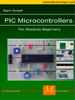
Teach Yourself PIC Microcontrollers | www.electronicspk.com | 1
M. Amer Iqbal Qureshi
M
icrotronics Pakistan
PIC Microcontrollers
Teach Yourself
For Absolute Beginners
www.electronicspk.com
Teach Yourself PIC Microcontrollers | www.electronicspk.com | 2
About This Book
This book, is an entry level text for those who want to explore the wonderful world of microcontrollers.
Electronics has always fascinated me, ever since I was a child, making small crystal radio was the best pro-
ject I still remember. I still enjoy the feel when I first heard my radio. Over the period of years and decades
electronics has progressed, analogs changed into digital and digital into programmable.
A few years back it was a haunting task to design a project, solely with gates and relays etc, today its ex-
tremely easy, just replace the components with your program, and that is it.
As an hobbyist I found it extremely difficult, to start microcontrollers, however thanks to internet, and ex-
cellent cataloging by Google which made my task easier.
A large number of material in this text has its origins in someone else’s work, like I made extensive use of
text available from Mikroelectronica and other sites.
This text is basically an accompanying tutorial for our PIC-Lab-II training board.
I wish my this attempt help someone, write another text.
Dr. Amer Iqbal
206 Sikandar Block
Allama Iqbal Town Lahore
Pakistan
Teach Yourself PIC Microcontrollers | www.electronicspk.com | 3
Acknowledgment
\ tÅ xåàÜxÅxÄç à{tÇ~yâÄ àÉ Åç ytÅ|Äç? áÑxv|tÄÄç f{tÅ|Å? ã{É áÑxÇà {ÉâÜá
Åt~|Çz gxt tÇw VÉyxx àÉ Åt~x Åx ãÉÜ~|Çz tÇw yÉÜ {xÜ ÄÉäx tÇw áâÑÑÉÜàA
`ç à{Üxx ~|wá? bátÅt? gt{t tÇw `âÇxxu? ã{É {täx uxxÇ t áÉâÜvx Éy |Ç@
áÑ|Ütà|ÉÇ tÇw xÇxÜzç? tÄãtçá ÑÄtç|Çz ã|à{ Åx tÇw Åt~|Çz à{x Ä|yx t ãÉÇwxÜyâÄ
xåÑxÜ|xÇvxA
\ ãÉâÄw Ä|~x àÉ à{tÇ~ Åç yÜ|xÇw? `ÜA [tÜÉÉÇ etá{|w? ã{É ÜxtÄÄç Åtwx
t Ç|vx xyyÉÜà àÉ zxà Åx áàtÜàxw? \ tÅ à{tÇ~yâÄ àÉ `ÜA f{t{|w TyÜ|w|? ã{É
wxáÑ|àx ux|Çz t uâáç Éyy|vxÜ? áÑxÇwá t ÄÉà Éy à|Åx ÉÇ {|á {Éuuç? {|á à{Éâz{à ÑÜÉäÉ~@
|Çz |wxtá tÜx ÜxtÄÄç tÑÑÜxv|tàxwA
Teach Yourself PIC Microcontrollers | www.electronicspk.com | 4
To My Mother,
Prof. Razia Dr. Razia Iqbal
and my Father,
Late Prof. Dr. M. Iqbal Qureshi
who really did an excellent job, in my
training and inspiration.
May Allah bless them.
Teach Yourself PIC Microcontrollers | www.electronicspk.com | 5
Table of Contents
Introduction to Microcontrollers 6
Understanding Hardware 27
Setting up the Programmer 35
Setting Up Proton Basic Compiler 38
Basic Programming Language … A Primer 41
I/O Ports 48
Writing Your First program 52
Reading Switches 57
Using Graphic LCD 66
Asynchronous Serial Communication 70
Sound and Digital Signals 79
Analog Module 88
On-Chip EEPROM 94
On-Chip CCP Capture | Compare | PWM 98
Pulse 103
Interrupts 105
Timers and Interrupts 109
I2C Communication 117
Basic Electronics 120
Expanding Microcontroller I/O Lines 124
H-Bridge and DC Motors 126
Stepper Motors 128
Real Time Clock 130
Making a frequency Counter 133
Working with Matrix LED Displays 139
MPLAB® and ICD-2 144
Using Boot Loader 145
Teach Yourself PIC Microcontrollers | www.electronicspk.com | 6
Chapter 1
Introduction to Microcontrollers
W
elcome to the wonderful world of microcontrollers. I presume that you are reading this text
because you are interested in learning and exploring microcontrollers. As you might be
aware micro-processors in general and micro-
controllers in particular have substantially changed
the electronics today. Now electronic devices and circuits are not
designed as electronic connections, but as software run within the
microcontrollers. So electronic devices today are the blend of
hardware and software.
This book will take you through all the steps necessary to learn
and explore PIC-Microcontrollers. We shall remain confined to a
particular class of microcontrollers, yet chances are that after
mastering this you will find migration to other devices quite a
bliss. This manual has been written specifically as a companion to
our PIC-Lab-II a microcontroller development board.
These small devices have revolutionized the world of electronics. Today microcontrollers are everywhere,
think of a device and you will find a microcontroller somewhere in it. May it be your remote control, air
conditioner, microwave oven, DVD player, television or cell phone all have a microcontroller sitting inside.
These small devices can do so much, that only imagination is the limit. Moreover they are very simple to
use, you don't need to be an expert in electronics to use them in your next project. A basic understanding of
electronics, and digital circuits is all that is required to get started. Once you are in the business, sky is the
limit. Think of any logical application and you will find microcontroller handling the job nicely.
Industrial automation including automatic assembly lines, robots and quality control systems all are backed
by some kind of microcontroller.
What is a Microcontroller?
So exactly what is a microcontroller or a microprocessor? This is the question which needs to be clarified
before putting the heads down. As a hobbyist or as a student of electronics you must have come across a
number of integrated circuits. These are small devices, with lots of circuitry inside them, having few con-
nections for external communication. However all these integrated circuits differ from each other, in terms
of function. The circuit inside an integrated circuit, may it be digital or analog, is purpose designed. Like
555, a very popular timing IC, has all the necessary circuitry inside to make various types of oscillators.
Similarly a 7447 is a binary to 7-segment decoder, and has input pins to accept binary coded decimal
(BCD) number, the output pins will then turn on and off accordingly to display the number on a 7-segment
display. So on an so forth, you come across hundreds and thousands of ICs with specific functions. In order
to get an application work, you must know specifically the function, input and output requirements of the
particular integrated circuit.
Microcontrollers and microprocessors are integrated circuits, but they differ fundamentally from other ICs.
They are a class in themselves, that the designers have not made them to do a particular job. As such when
you buy them from the market, you can not specify what function it will do. In order to get some useful
function, these ICs have to be configured. Thus a microprocessor or microcontroller can be configured to
check the status of a button, and then turn a motor ON or OFF. While the same IC can be configured later,
to read the status of an infra-red sensor, decode the signal and turn another device ON or OFF. If these two
types of circuitries were to be made using conventional digital ICs, it would have required a large number
of components. Moreover any change in the specification, like change of Infra-Red codes would result in
total change in design! Using a configurable IC, is a great idea. Not only the same IC, can be configured to
Teach Yourself PIC Microcontrollers | www.electronicspk.com | 7
do different tasks, but a change in specifications can easily be implemented by just changing the device
configuration. This greatly facilitated the engineers and hobbyists to rapidly develop new electronic
devices, and continuously improve previous ones. Not only the hardware requirements decreased, but also
design time, and time to market were decreased.
Microcontrollers and microprocessors therefore took over the market. Large hardware designs were
reduced, and most of the circuitry was replaced by the configuration scripts. Today we call this ability to
configure a microprocessor or microcontroller, programming.
A program is nothing but a series of instructions, in a correct and logical manner to instruct the
microprocessor respond to various inputs. By changing the program, the behavior of microcontroller will
change. Think of it as a music system. The manufacturer has not designed it to produce any particular
sounds out of its speakers. Yet it has all the necessary circuitry to do that. What music it will produce would
depend upon the tape, or CD inserted. Thus you change the CD, and the same hardware is playing different
thing. So we can say that the music system, is a programmable device, and the information stored on tape,
or CD is the program, or instructions to help the music system, make sounds.
Similarly microprocessors and microcontrollers, are programmed to do a job. The job can be changing a TV
channel to controlling complex movements of a robot. All these applications have a microcontroller doing
its specific job. It can be astonishing to find the same microcontroller in the remote control, and the robot.
In one place it is driving an infra-red LED and in other it is driving the motors.
Take another example. Consider plain paper and pencil. Now you have a choice of 26 alphabets, 0-9
numbers and few others like space, full stop etc. that is it. Not much hardware, only paper and pencil, and
not much choice of letters, just 26 + few more. What you can do with it. You can do miracles. Write a
complete thesis, a poem, a novel, an essay or what not. It all depends how you organize those letters. Using
the pencil and paper. So the same hardware serving thousands of different jobs. The choice of letters are the
instructions you can give, and paper is your microcontroller, whereas pencil is a device through which you
transfer the idea in your mind, to the paper. Once transferred you do not need the pencil, to use the book, or
notebook.
This example fits exactly on the scenario of microcontrollers and microprocessors. Thus you have to learn
the instructions your particular microcontroller understands, and what those instructions order it to do. Then
its your mind, and ideas how you play with these instructions to get your job done. Literally there are
hundreds of methods to get the same job done. Just like in English, there many ways you can arrange the
alphabets, to convey the same message.
Difference between a Microprocessor and Microcontroller
Essentially these two devices are similar, but with a little bit of difference. A CPU which is the heart of
these devices needs a host of external devices to make it communicate with real-world. A typical system
would need a system to read the inputs from
keyboard, and write outputs to a terminal,
store intermediate processing data into some
memory, and to keep permanent information
into some safe place. These devices which
are independent circuits, work in harmony
with the CPU, to make one system. In a
typical Personal Computer these devices are
attached to the CPU, using hard-wired
connections. This makes the system more
flexible, that means you can add more
memory, change capacity of hard drives, add
or remove CD-ROMs, sound cards etc.
A microcontroller on the other hand is made
up of most of these devices built exactly
within the same package. Your
microcontroller will therefore contain, the
CPU, RAM, ROM, Timers, I/O etc. all packed within one integrated circuit. This facilitates the
development process, as well as reduce the requirements of external components, however this also means
Teach Yourself PIC Microcontrollers | www.electronicspk.com | 8
you can not change, the number and type of integrated devices. The applications where a microcontroller
will be used, vary. They are usually quite simple, and do not require as much processing power as a PC
does, so the microcontrollers with varying amounts of RAM, ROM, I/O lines and timers etc have been
made available. Essentially all are almost same, and they only vary in the number of resources available on
them. So for a particular application you chose a microcontroller, not the one which has maximum
resources, but the one which has just enough to do the job.
Thus a microcontroller is a complete, small scale computer with all the necessary devices on-board. All you
need is the external hardware, which you want to drive, like sensors and motors etc.
Why there are to many different Microcontrollers?
Well after the idea of having a programmable device, many electronics manufacturers took the idea to
develop their own chip. The internal architecture therefore differs among the manufacturers but from our
point they are almost similar. Like there are so many different car manufacturers, Toyota, Suzuki, Honda,
Mercedes and so on. Each one manufactures the cars with their own internal technologies, their engines,
aerodynamics, peripherals all are different in specifications, yet if you can drive one car, chances are you
will not find it difficult to drive another, is that not so. Despite being different in power, cylinders, valves,
type of fuel etc, yet they have the same basic architecture and same basic theme.
So learning one microcontroller facilitates learning the other. Moreover the same company manufactures
many different microcontrollers, which are all almost compatible. This is again like an automobile
company. They make cars for many different types of users. Some bigger while others smaller. In addition
to cars, they also manufacture other locomotives, like vans, truck and buses etc. All these have similar idea,
but the nature of job they are required to do is different. Similarly in electronics the requirements of the
project vary. For example to make a security device, you need little memory, whereas to make a data logger
you need lots of memory. A remote control will not need to display data on LCD, so needs lesser number of
I/O lines, whereas an industrial control unit will need to display its data, and therefore needs more I/O lines.
A calculator needs only digital input, whereas a temperature controller needs to acquire analog data. These
differences in requirements, makes the manufacturers produce different microcontrollers with different
memory size, number of I/O lines and number of integrated peripheral devices. Otherwise they are all
similar to use. Again, if you have mastered one, its easy to migrate to another. So the type of
microcontroller to be used in a given project will be determined by the exact requirements.
How did Microcontrollers evolve?
The situation we find ourselves today in the field of microcontrollers had its beginnings in the development
of technology of integrated circuits. This development has enabled to store hundreds of thousands of
transistors into one chip. That was a precondition for manufacture of microprocessor and the first
computers were made by adding external peripherals such as memory, input/output lines, timers and others
to it. Further increasing of package density resulted in creating an integrated circuit which contained both
processor and peripherals. That is how the first chip containing a microcomputer later known as a
microcontroller was developed.
In the year 1969, a team of Japanese engineers from BUSICOM company came to the USA with a request
that a few integrated circuits for calculators were to be designed according to their projects. The request
was set to INTEL company and Marcian Hoff was in charge of the project there. Since having been
experienced in working with a computer PDP8, he came to an idea to suggest fundamentally different
solution instead of suggested design. That solution presumed that the operation of integrated circuit was to
be determined by the program stored in the circuit itself. It meant that configuration would be simpler, but it
would require far more memory than the project proposed by Japanese engineers. After a while, even
though the Japanese engineers were trying to find an easier solution, Marcian’s idea won and the first
microprocessor was born. A major help with turning an idea into a ready-to-use product, Intel got from
Federico Faggin. Nine months after his arrival to Intel he succeeded in developing such a product from its
original concept. In 1971 Intel obtained the right to sell this integrated circuit. Before that Intel bought the
license from BUSICOM company which had no idea what a treasure it had. During that year, a
microprocessor called the 4004 appeared on the market. That was the first 4-bit microprocessor with the
speed of 6000 operations per second. Not long after that, American company CTC requested from Intel and
Texas Instruments to manufacture 8-bit microprocessor to be applied in terminals. Even though CTC gave
up this project at last, Intel and Texas Instruments kept working on the microprocessor and in April 1972
Teach Yourself PIC Microcontrollers | www.electronicspk.com | 9
the first 8-bit microprocessor called the 8008 appeared on the market. It was able to address 16Kb of
memory, had 45 instructions and the speed of 300,000 operations per second. That microprocessor was the
predecessor of all today’s microprocessors. Intel kept on developing it and in April 1974 it launched 8-bit
processor called the 8080. It was able to address 64Kb of memory, had 75 instructions and initial price was
$360.
In another American company called Motorola, they quickly realized what was going on, so they launched
8-bit microprocessor 6800. Chief constructor was Chuck Peddle. Apart from the processor itself, Motorola
was the first company that also manufactured other peripherals such as 6820 and 6850. At that time many
companies recognized greater importance of microprocessors and began their own development. Chuck
Peddle left Motorola to join MOS Technology and kept working intensively on developing
microprocessors.
At the WESCON exhibition in the USA in 1975, a crucial event in the history of the microprocessors took
place. MOS Technology announced that it was selling processors 6501 and 6502 at $25 each, which
interested customers could purchase immediately. That was such sensation that many thought it was a kind
of fraud, considering that competing companies were selling the 8080 and 6800 at $179 each. On the first
day of exhibit, in response to the competitor, both Motorola and Intel cut the prices of their microprocessors
to $69.95. Motorola accused MOS Technology and Chuck Peddle of plagiarizing the protected 6800.
Because of that, MOS Technology gave up further manufacture of the 6501, but kept manufacturing the
6502. It was 8-bit microprocessor with 56 instructions and ability to directly address 64Kb of memory. Due
to low price, 6502 became very popular so it was installed into computers such as KIM-1, Apple I, Apple
II, Atari, Commodore, Acorn, Oric, Galeb, Orao, Ultra and many others. Soon appeared several companies
manufacturing the 6502 (Rockwell, Sznertek, GTE, NCR, Ricoh, Commodore took over MOS
Technology). In the year of its prosperity 1982, this processor was being sold at a rate of 15 million
processors per year!
Other companies did not want to give up either. Frederico Faggin left Intel and started his own company
Zilog Inc. In 1976 Zilog announced the Z80. When designing this microprocessor Faggin made the crucial
decision. Having been familiar with the fact that for 8080 had already been developed he realized that many
would remain loyal to that processor because of great expenditure which rewriting of all the programs
would result in. Accordingly he decided that a new processor had to be compatible with the 8080, i.e. it had
to be able to perform all the programs written for the 8080. Apart from that, many other features have been
added so that the Z80 was the most powerful microprocessor at that time. It was able to directly address
64Kb of memory, had 176 instructions, a large number of registers, built in option for refreshing dynamic
RAM memory, single power supply, greater operating speed etc. The Z80 was a great success and
everybody replaced the 8080 by the Z80. Certainly the Z80 was commercially the most successful 8-bit
microprocessor at that time. Besides Zilog, other new manufacturers such as Mostek, NEC, SHARP and
SGS appeared soon. The Z80 was the heart of many computers such as: Spectrum, Partner, TRS703, Z-3
and Galaxy.
In 1976 Intel came up with an upgraded version of 8-bit microprocessor called the 8085. However, the Z80
was so much better that Intel lost the battle. Even though a few more microprocessors appeared later on the
market (6809, 2650, SC/MP etc.), everything was actually decided. There were no such great improvements
which could make manufacturers to change their mind, so the 6502 and Z80 along with the 6800 remained
chief representatives of the 8-bit microprocessors of that time.
The PIC Microcontroller
Although microcontrollers were being developed since early 1970’s real
boom came in mid 1990’s. A company named Microchip® made its first
simple microcontroller, which they called PIC. Originally this was
developed as a supporting device for PDP computers to control its
peripheral devices, and therefore named as PIC, Peripheral Interface
Controller. Thus all the chips developed by Microchip® have been named
as a class by themselves and called PIC. Microchip® itself does not use
this term anymore to describe their microcontrollers, however use PIC as part of product name. they call
their products MCU’s.
A large number of microcontroller designs are available from microchip. Depending upon the architecture,
memory layout and processing power. They have been classified as low range, mid range, high range and
Teach Yourself PIC Microcontrollers | www.electronicspk.com | 10
now digital signal processing microcontrollers.
The beauty of these devices is their easy availability, low cost and easy programming and handling. This
has made PIC microcontrollers as the apple of hobbyists and students eyes.
We shall be talking about mid-range PIC
microcontrollers, and use PIC18F452 as a prototype
in this manual to explore them. Knowledge gained by
learning and exploring one microcontroller is almost
90% applicable on other microcontrollers of the same
family. The only difference is in availability of
resources on different chips.
General Organization of PIC
Microcontrollers
Although we shall talk in detail on various aspects of
these chips in relevant sections, here I would like to
give a brief introduction on the overall business
involved. Fig-2 shows the pin out details of a very
popular 40-pin PIC microcontroller, PIC16F877. as
you can see that each pin has been assigned a number
of functions. Sometimes two and sometimes three.
This situation is very common in microcontrollers, as
there is always more which your microcontroller can
offer, yet the number of pins on a given package is
limited.
In a given circuit/application a pin is usually tied to a specific job, and all functionality of a pin is usually
not required, however you make opt to use the specific pin your own way.
The specific function of a pin is selected by configuring various bits of internal registers. The number and
names of these special function registers (SFRs) vary from device to device as some devices have limited
functionality while others have more. Nevertheless if we are talking about a function which is present in
both devices, its SFR will be same. The selection and settings of these SFR’s is the key to successful
programming. It is therefore mandatory to go through the data sheets of the device before starting a project.
Second important thing to know is that the devices with same number of pins (from microchip®), are all
pin-compatible. Which means if you design a project for 40 pin PIC microcontroller, and later want to
replace the chip with another 40 pin PIC the pins are all compatible. It is also good to know that a pin
labeled as lets say RB0 is located on pin 33 of PIC 16F877, but the same pin is available on pin 6 in 18 pin
PIC16F628. the pins are functionally same, as long as their names are same. So if you develop a project
while experimenting on 18F452 using pin RB0, after successful testing you want to transport the project to
an 18 pin device, which also has RB0 on it, apart from pin number on package, and recompiling the
program, you don have to bother much about anything else.
Power Supply
PIC microcontrollers use TTL logic, and therefore expect a
well regulated 5V power supply. The supply may however
range from 3.5V to 5.5V. These microcontrollers require
very small amount of current. Indeed these devices have
been labeled as nano-watt technology devices. The logical
levels are also same, a signal from 0 to about 2V is
considered as logical ‘0’ and a signal from 3.5V to 4.5V is
considered as logical ‘1’. In order to communicate with
devices using higher logical voltages, consider level
conversion.
MCLR , Master Clear
On every PIC microcontroller you will find a pin labeled as MCLR. This pin has two basic functions. It is
Fig-2 Showing Pin Outs of PIC-16F877 Microcontroller
Fig-3 wiring MCLR Pin
Teach Yourself PIC Microcontrollers | www.electronicspk.com | 11
used to reset the microcontroller, like soft-boot. As well as to put the microcontroller into programming
mode. The MCLR pin when connected to ground, will reset the microcontroller, and keep it in reset state,
till the ground connection is released. After that the microcontroller will have all its RAM reset, and
program execution will begin, just like the system has been just powered on. A 10K pull up resistor is
usually connected with the pin, to keep it high when reset switch is released.
The same pin will also work as program mode pin. When a new software is to be downloaded into the
microchip, about 12V are applied to the MCLR pin, by your programming device. This can be done right in
your circuit, or by taking the IC out of circuit and putting it into the IC socket on your programmer. We
shall talk more about this in section on programming. The 10K resistor is then useful to avoid 12V reaching
VCC and therefore to other devices.
Analog and Digital Data
Our microprocessors use digital data to represent everything. Even music, videos and images all are
represented as digital data, which is a series of logical ‘0’ and ‘1’. However our real world data is not
digital. It is rather analog. It is rightly said, “We live in an analog world, but process the data in digital
world”. Real world data like light, temperature, pressure, heat, height, distance, speed, force etc. all are
analog data. In order to utilize these data we have to acquire them with specific sensors or transducers and
then convert into digital format for use within microprocessor’s digital world. Many other microcontrollers
require an external ADC chip to implement this, however this feature has been nicely built into PIC
microcontrollers. The number of Analog channels will vary among devices and some devices will not have
this feature on-board. Pins labeled as AN0, AN1 etc are for analog data if required, however they can also
function as normal digital pins to work with digital data. As previously said this selection is made by
configuring specific registers in microcontroller.
BASIC CONCEPTS
Did you know that all people can be classified
into one of 10 groups- those who are familiar
with binary number system and those who are
not familiar with it. You don’t understand? That
means that you still belong to the later group. If
you want to change your status read the
following text. Text describing briefly some of
the basic concepts used further in this book (just
to be sure that we discuss the same issues).
World of numbers
Mathematics is such a good science! Everything
is so logical and is as simple as that. The whole
universe can be described with ten digits only.
But, does it really have to be like that? Do we
need exactly ten digits? Of course not, it is only
a matter of habit. Remember the lessons from
the school. For example, what does the number
764 mean: four units, six tens and seven hundreds. Simple! Could it be described in a bit more complicated
way? Of course it could: 4 + 60 + 700. Even more complicated? Naturally: 4*1 + 6*10 + 7*100. Could this
number look a bit more “scientific”? The answer is yes: 4*10^0 + 6*10^1 + 7*10^2. What does it actually
mean? Why do we use exactly these numbers: 100, 101 and 102 ? Why is it always about the number 10?
That is because we use ten different digits (0, 1, 2, 8, 9). In other words, because we use base-10 number
system, i.e. decimal number system. It is easier to work with decimal numbers, however computers can not
do so, they use only two digits, 0 and 1. these are represented within a computer by presence or absence of
volts on a specific line.
Binary number system
What would happen if only two digits would be used- 0 and 1? Or if we would not know to determine
whether something is 3 or 5 times greater than something else? Or if we would be restricted when
comparing two sizes, i.e. if we could only state that something exists (1) or does not exist (0)? Nothing
Fig. 4 Different methods of representing a decimal number
Teach Yourself PIC Microcontrollers | www.electronicspk.com | 12
special would happen, we would keep on using numbers in the same way, but they would look a bit
different. For example: 11011010. How many pages of a book does the number 11011010 include? In order
to learn that, follow the same logic like in the previous example, but in inverse order. Have in mind that all
this is about mathematics with only two digits- 0 and 1, i.e. base-2 number system (binary number system).
Clearly, it is the same number represented in two different ways. The only difference is in the number of
digits necessary for writing some number. One digit (2) is used to write the number 2 in decimal system,
whereas two digits (1 and 0) are used
to write that number in binary system.
Do you now agree with the first
sentence in this text? Welcome to the
world of binary arithmetic! Do you
have any idea where it is used?
Excepting strictly controlled
laboratory conditions, the most
complicated electronic circuits cannot
with accuracy determine difference
between two sizes (two voltage
values, for example) if they are too
small (lower than several volts). The
reasons for that are electrical noises
and something quite uncertainly called “realistic working environment” (unpredictable changes of power
supply voltage, temperature changes, tolerance to values of built in components etc.). Imagine a computer
which would operate upon decimal numbers by recognizing 10 digits in the following way: 0=0V, 1=5V,
2=10V, 3=15V, 4=20V 9=45V !? Did anybody say batteries? Far simpler solution is the use of binary
logic where 0 indicates that there is no voltage and 1 indicates that there is voltage. Simply, it is easier to
write 0 or 1 instead of “there is no voltage” or “there is voltage”. It is so called logic zero (0) and logic one
(1) which electronics perfectly cope with and easily performs all those endlessly complex mathematical
operations. It is apparently electronics which in reality applies mathematics in which all numbers are
represented by two digits only and in which it is only important to know whether there is voltage or not. Of
course, we are talking about digital electronics.
Hexadecimal number system
At the very beginning of the computer development it was realized that people had many difficulties in
handling binary numbers. Because of
that, a new number system which
facilitated work has been established.
This time, it is about number system
using 16 different digits. The first ten
digits are the same as digits we are
used to (0, 1, 2, 3, 9) but there are
six digits more. In order to keep from making up new symbols, the six letters of alphabet A, B, C, D, E and
F are used. In consequence of that, a hexadecimal number system consisting of digits: 0, 1, 2, 3, 4, 5, 6, 7,
8, 9, A, B, C, D, E, F has been established. What is the purpose of this seemingly bizarre combination? Just
look how perfectly everything fits the story about binary numbers.
The largest number that can be represented by 4 binary digits is the number 1111. It corresponds to the
number 15 in decimal system. That number is in hexadecimal system represented by only one digit F. It is
the largest one-digit number in hexadecimal system. Do you see how skillfully it is used? The largest
number written with eight binary digits is at the same time the largest two-digit hexadecimal number. Have
in mind that the computer uses 8-digit binary numbers. Accidentally?
BCD code
BCD code is actually a binary code for decimal numbers only. It is used to enable electronic circuits to
communicate in decimal number system with peripherals and in binary system within “their own world”. It
consists of 4-digit binary numbers which represent the first ten digits (0, 1, 2, 3 8, 9). Simply, even
though four digits can give total of 16 possible combinations, only first ten are used.
Fig. 5 Showing Representation of Binary Numbers
Fig. 6 Showing Hexadecimal-Binary Number
Teach Yourself PIC Microcontrollers | www.electronicspk.com | 13
Number system conversion
Binary number system is the most commonly used and decimal system is the most understandable while
hexadecimal system is somewhere between them. Therefore, it is very important to learn how to convert
numbers from one number system to another, i.e. how to turn series of zeros and units into values
understandable for us.
Binary to decimal number conversion
Digits in a binary number have different values depending on their position in that number. Additionally,
each position can contain either 1 or 0 and its value may be easily determined by its position from the right.
To make the conversion of a binary number to decimal it is necessary to multiply values with the
corresponding digits (0 or1) and add all the results. The magic of binary to decimal number conversion
works You doubt? Look at the example:
110 = 1*2^2 + 1*2^1 + 0*2^0 = 6
It should be further noticed that for decimal numbers from 0 to 3 it is enough to have two binary digits. For
greater values, new binary digits must be added. Thus, for numbers from 0 to 7 it is enough to have three
digits, for numbers from 0 to 15- four digits etc. Simply speaking, the largest binary number consisting of n
digits is obtained when the base 2 is raised by n. The result should be afterwards subtracted by 1. For
example, if n=4:
2^4 - 1 = 16 - 1 = 15
Accordingly, using 4 binary digits it is possible to represent decimal numbers from 0 to 15, including these
two digits, which amounts to 16 different values in total.
Hexadecimal to decimal number conversion
In order to make conversion of a hexadecimal number to decimal, each
hexadecimal digit should be multiplied with the number 16 raised by it’s position
value. For example:
Hexadecimal to binary number conversion
It is not necessary to perform any calculation in order to convert hexadecimal
number to binary number system. Hexadecimal digits are simply replaced by the
appropriate four binary digits. Since the maximal hexadecimal digit is equivalent to decimal number 15, it
is needed to use four binary digits to represent one hexadecimal digit. For example:
Marking numbers
Hexadecimal number system is along with binary and decimal number systems considered to be the most
important for us. It is easy to make conversion of any hexadecimal number to binary and it is also easy to
remember it. However, these conversions as well as common use of different number systems may cause
confusion. For example, what does the statement “It is necessary to count up 110 products on assembly
line” actually mean? Depending on whether it is about binary, decimal or hexadecimal system, the result
could be 6, 110 or 272 products, respectively! Accordingly, in order to avoid misunderstandings, different
prefixes and suffixes are directly added to the numbers. The prefix $ or 0x as well as the suffix h marks the
numbers in hexadecimal system. For example, hexadecimal number 10AF may look as follows $10AF,
0x10AF or 10AFh. Similarly, binary numbers usually get the suffix % or 0b, whereas decimal numbers get
Fig. 7 Showing Hexadecimal to decimal conversion
Teach Yourself PIC Microcontrollers | www.electronicspk.com | 14
the suffix D. Commonly if no suffix is used the number is assumed to be decimal.
Bit
Theory says a bit is the basic unit of information Let us neglect such a dry explanation for a moment and
take a look at what it is in practice. The answer is- nothing special- a bit is a binary digit. Similar to decimal
number system in which digits in a number do not have the same value ( for example digits in the number
444 are the same, but have different values), the “significance” of some bit depends on the position it has in
binary number. Therefore, there is no point to talk about units, tens etc. Instead, here it is about zero bit
(rightmost bit), first bit (second from the right) etc. In addition, since the binary system uses two digits only
(0 and 1), the value of one bit can be 0 or 1.
Do not let you be confused if you find some bit has value 4, 16 or 64. It means that bit’s values are
represented in decimal system. Simply, we have got so much accustomed to the usage of decimal numbers
that these expressions became common. It would be correct to say for example, “the value of the sixth bit in
binary number is equivalent to decimal number 64”. But we all are just humans and a habit does its
own Besides, how would it sound “number: one-onezero- one-zero ”
Byte
A byte or a program word consists of eight bits placed next to each other. If a bit is a digit, it is logical that
bytes represent numbers. All mathematical operations can be performed upon them, like upon common
decimal numbers. As It is case with digits of any other number, byte digits do not have the same
significance. The largest value has the left-most bit called most significant bit (MSB). The right-most bit
has the least value and is therefore called least significant bit (LSB). Since eight zeros and units of one byte
can be combined in 256 different ways, the largest decimal number which can be represented by one byte is
255 (one combination represents zero).
Concerning terminology used in computer science, a concept of nibble should be clarified. Somewhere and
somehow, this term referred to as half a byte came up. Depending on which half of the byte we are talking
about (left or right), there are “high” and “low” nibbles.
Logic circuits
Have you ever wondered what electronics within some digital integrated circuit, microcontroller or
processor look like? What do the circuits performing complicated mathematical operations and making
decisions look like? Do you know that their seemingly complicated schematics comprise only a few
different elements called “logic circuits” or “logic gates”?
The operation of these elements is based on the
principles established by British mathematician
George Boole in the middle of the 19th century-
meaning before the first bulb was invented! In
brief, the main idea was to express logical
forms through algebraic functions. Such
thinking was soon transformed into a practical
product which far later evaluated in what today
is known as AND, OR and NOT logic circuits.
The principle of their operation is known as
Fig. 8 High and Low Nibbles of a Byte
Fig. 9 Logical AND gate with its Truth Table
Teach Yourself PIC Microcontrollers | www.electronicspk.com | 15
Boolean algebra. As some program instructions used by the microcontroller perform the same way as logic
gates but in form of commands, the principle of their operation will be discussed here.
AND gate
A logic gate “AND” has two or more inputs
and one output. Let us presume that the gate
used in this case has only two inputs. A logic
one (1) will appear on its output only in case
both inputs (A AND B) are driven to logic one
(1). That’s all! Schematic symbol of AND gate
is shown in the figure on the right.
Additionally, the table shows mutual
dependence between inputs and output.
In case the gate has more than two inputs, the
principle of operation is the same: a logic one
(1) will appear on its output only in case all
inputs are driven to logic one (1). Any other
combination of input voltages will result in
logic zero (0) on its output.
When used in a program, logic AND operation
is performed by the program instruction, which
will be discussed later. For the time being, it is
enough to remember that logic AND in a
program refers to the corresponding bits of two
registers.
OR gate
Similar to the previous case, OR gate also has
two or more inputs and one output. The gate
with only two inputs will be considered in this
case as well. A logic one (1) will appear on its
output in case either one or another output (A
OR B) is driven to logic one (1). In case the OR
gate has more than two inputs, the following
applies: a logic one (1) appears on its output in
case at least one input is driven to logic one (1).
In case all inputs are driven to logic zero (0),
the output will be driven to logic zero (0).
Not gate
This logic gate has only one input and only one output.
It operates in an extremely simple way. When logic zero
(0) appears on its input, a logic one (1) appears on its
output and vice versa. This means that this gate inverts
signal by itself and because of that it is sometimes called
Fig. 10 Use of Logical AND in Software
Fig. 11 The OR Gate with Truth Table
Fig. 12 The OR being Used in Software
Fig. 13 The NOT Gate
Teach Yourself PIC Microcontrollers | www.electronicspk.com | 16
inverter.
In a program, logic NOT operation is performed on one byte bits. The result is
a byte with inverted bits. If byte bits are considered to be a number, inverted
value is actually a complement of that number, i.e. The complement of a
number is what is needed to add to it to make it reach the maximal 8 bit value
(255).
EXCLUSIVE OR gate
This gate is a bit complicated comparing to other gates. It represents combination of all previously
described gates. It is not simple to define mutual dependence of input and output, but we will anyway try to
do it. A logic one (1) appears on its output only in case the inputs have different logic states.
In a program, this operation is commonly used to compare two bytes. Subtraction may be used for the same
purpose (if the result is 0, bytes are equal). The advantage of this logic operation is that there is no danger
Teach Yourself PIC Microcontrollers | www.electronicspk.com | 17
to subtract larger number from smaller one.
Register
A register or a memory cell is an electronic circuit which can memorize the state of one byte. In other
words, what is a byte theoretically, it is a register practically.
Special Function Registers (SFR registers)
In addition to the registers which do not have
any special and predetermined function, every
microcontroller has also a number of registers
whose function is predetermined by the
manufacturer. Their bits are connected (literally)
to internal circuits such as timers, A/D
converter, oscillators and others, which means
that they are directly in command of the
operation of the microcontroller. If you imagine
that as eight switches which are in command of
some smaller circuit within the microcontroller-
you are right! SFRs do exactly that!
Input / Output ports
In order that the microcontroller is of any use, it has to be connected to additional electronics, i.e.
peripherals. For that reason, each microcontroller has one or more registers (called “port” in this case)
connected to the microcontroller pins. Why input/output? Because you can change the pin’s function as you
wish. For example, suppose you want your device to turn on and off three signal LEDs and simultaneously
monitor logic state of five sensors or push buttons. In accordance with that, some of ports should be
configured so that there are three outputs (connected to LEDs) and five inputs (connected to sensors). It is
simply performed by software, which means that pin’s function can be changed during operation.
One of more important feature of I/O pins is maximal current they can give/get. For the most
microcontrollers, current obtained from one pin is sufficient to activate a LED or other similar low-current
consumer (10-20 mA). If the microcontroller has many I/O pins, then maximal current of one pin is lower.
Simply, you cannot expect all pins to give maximal current if there are more than 80 of them on one
microcontroller.
Another important pin feature is to (or not to) have pull-up resistors. These resistors connect pin to positive
power supply voltage and their effect is visible when the pin is configured as input connected to mechanical
switch or push button. The later versions of the microcontrollers have pull-up resistors connected to and
disconnected from the pins by software.
Usually, each I/O port is under control of another
SFR, which means that each bit of that register
determines state of the corresponding microcontroller
pin. For example, by writing logic one (1) to one bit of
that control register SFR, the appropriate port pin is
automatically configured as input. It means that
voltage brought to that pin can be read as logic 0 or 1.
Otherwise, by writing zero to the SFR, the appropriate
port pin is configured as output. Its voltage (0V or 5V)
corresponds to the state of the appropriate bit of the
port register.
Memory unit
Memory is part of the microcontroller used for data
storage. The easiest way to explain it is to compare it
with a big closet with many drawers. Suppose, the
drawers are clearly marked so that it is easy to access
any of them. It is enough to know the drawer’s mark
Teach Yourself PIC Microcontrollers | www.electronicspk.com | 18
to find out its contents.
Memory components are exactly like that. Each memory address corresponds to one memory location. The
content of any location becomes known by its addressing. Memory consists of all memory locations and
addressing is nothing but selecting one of them. This means that, on one hand it is necessary to select the
desired memory location, on the other hand it is necessary to wait for the contents of that location. In
addition to read, memory also has to allow writing to these locations. There are several types of memory
within the microcontroller:
ROM memory (Read Only Memory)
ROM memory is used to permanently save program being executed. Clearly, the size of a program that can
be written depends on the size of this memory. Today’s microcontrollers commonly use 16-bit addressing,
which means that they are able to address up to 64 Kb memory, i.e. 65535 locations. For the sake of
illustration, if you are the beginner, your program will rarely exceed limit
of several hundreds instructions. There are several types of ROM.
Masked ROM. Microcontrollers containing this ROM are reserved for
the great manufacturers. Program is loaded into the chip by the
manufacturer. In case of large scale manufacture, the price is very low.
Forget it
OTP ROM (One Time Programmable ROM). If the microcontroller
contains this memory, you can download a program into the chip, but the
process of program downloading is “one-way ticket”, meaning that it can
be done only once. If you after downloading detect some error in a
program, the only thing you can do is to correct it and download that
program to another chip.
UV EPROM (UV Erasable Programmable ROM) Both manufacturing process and characteristics of this
memory are completely identical to OTP ROM. However, the package of this microcontroller has
recognizable “window” on the upper side. It enables surface of the silicon chip to be lit by an UV lamp,
which has for the result that complete program is cleared and a new program download is enabled.
Installation of this window is very complicated, which normally affects the price. From our point of view,
unfortunately- negative…
Flash memory. This type of memory was invented in the 80s in laboratories of INTEL company and were
represented as successor of UV EPROM. Since the contents of this memory can be written and cleared
practically unlimited number of times, the microcontrollers with Flash ROM are ideal for learning,
experimentation and small-scale manufacture. Because of its popularity, the most microcontrollers are
manufactured in flash version today. So, if you are going to buy a microcontroller, the right one is
definitely Flash!
RAM memory (Random Access Memory).
Once the power supply is off the contents of RAM is cleared. It is used for temporary storing data and
intermediate results created and used during the operation of the microcontroller. For example, if the
program performs addition (of whatever), it is necessary to have a register representing what in everyday
life is called “sum”. For that purpose, one of the registers in RAM is called “sum” and used for storing
results of addition.
EEPROM memory (Electrically Erasable Programmable ROM)
The contents of this memory may be changed during operation (similar to RAM), but remains permanently
saved even upon the power supply goes off (similar to ROM). Accordingly, EEPROM is often used to store
values, created during operation, which must be permanently saved. For example, if you design an
electronic lock or an alarm, it would be great to enable the user to create and enter a password on his/her
own. Of course, a new password must be saved upon power supply goes off. In such and similar cases, the
ideal solution is the microcontroller with embedded EEPROM.
Interrupt
Most programs use somehow interrupts in regular program execution. What does it actually mean? The
purpose of the microcontroller is mainly to react on changes in its surrounding. In other words, when some
Teach Yourself PIC Microcontrollers | www.electronicspk.com | 19
event takes place, the microcontroller does something For example, when you push a button on remote
controller, the microcontroller will register it and respond to the order by changing a channel, turn the
volume up or down etc. The bottom line is that the microcontroller spends the most of its time in endlessly
checking a few buttons- for hours, days It’s not practical, is it?
Because of and similar situations, the microcontroller has learned during its evolution a trick. Instead of
checking each pin or bit constantly, the microcontroller has left the “wait issue” to the “specialist” which
will react only in case something worth attention happens.
Signal which inform the central processor about such event is called an INTERRUPT.
Central Processor Unit - CPU
As its name indicates, this is a unit which monitors and controls all processes inside the microcontroller. It
consists of several smaller units, of which the most important are:
• Instruction Decoder is a part of electronics which recognizes program instructions and runs other
circuits on the basis of that. The “instruction set” which is different for each microcontroller family
expresses the abilities of this circuit.
• Arithmetical Logical Unit (ALU) performs all mathematical and logical operations upon data.
• Accumulator is a SFR closely related to the operation of ALU. It is a kind of working desk used for
storing all data upon which some operation should be performed (addition, shift/move etc.). It also
stores results ready for use in further processing. One of SFRs, called Status Register (PSW), is closely
related to the accumulator. It shows at any moment the “status” of a number stored in the accumulator
(number is greater or less than zero etc.).
Bus
Physically, the bus consists of 8, 16 or more wires.
There are two types of buses: address and data bus.
The first one consists of as many lines as necessary for
memory addressing. It is used to transmit address from
CPU to memory. The later one is as wide as data, in
our case it is 8 bits or wires wide. It is used to connect
all circuits inside the microcontroller.
Serial communication
Connection between the microcontroller and
peripherals via input/output ports is the ideal solution
for shorter distances, up to several meters. However, in
other cases - when it is necessary to establish
communication between two devices on longer distances or when for some other reason it is not possible to
use parallel connection - such a simple solution is out of question. In those and similar situations, serial
communication is the solution imposing itself.
Teach Yourself PIC Microcontrollers | www.electronicspk.com | 20
Today, most microcontrollers have built in several different systems for serial communication as a standard
equipment. Which of these systems will be used in the very case depends on many factors of which the
most important are:
• How many devices the microcontroller has to exchange data with?
• How fast the data exchange has to be?
• What is the distance between devices?
• Is it necessary to send and receive data simultaneously?
One of the most important thing concerning serial communication is the Protocol which should be strictly
observed. It is a set of rules which must be applied in order the devices can correctly interpret data they
mutually exchange. Fortunately, the microcontrollers automatically take care of that, so the work of the
programmer/user is reduced to simple write (data to be sent) and read (received data).
Baud Rate
The term Baud rate is commonly used to denote the number of bits transferred per second [bps].
It should be noted that it refers to bits,
not bytes! It is usually required by the
protocol that each byte is transferred
along with several control bits. It
means that one byte in serial data
stream may consist of 11 bits. For
example, if the baud rate is 300 bps
then maximum 37 and minimum 27
bytes may be transferred per second,
which depends on type of connection
and protocol in use.
The most commonly used serial communication systems are:
I2C Protocol (Two wire System)
I2C (Inter Integrated Circuit) is a system used when the distance between the microcontrollers is short and
specialized integrated circuits of a new generation (receiver and transmitter are usually on the same printed
circuit board). Connection is established via two
conductors- one is used for data transfer whereas
another is used for synchronization (clock signal).
As seen in figure, in such connection, one device
is always master. It performs addressing of one
slave chip (subordinated) before communication
starts. In this way one microcontroller can
communicate with 112 different devices. Baud
rate is usually 100 Kb.sec (standard mode) or 10
Kb/sec (slow baud rate mode). Systems with the
baud rate of 3.4 Mb/sec have recently appeared. The distance between devices which communicate via an
inter-integrated circuit bus is limited to several meters.
SPI (Three Wire Serial - Parallel Interface)
SPI (Serial Peripheral Interface Bus) is a system for serial communication which uses four conductors
(usually three)- one for data receiving, one for data sending, one for synchronization and one (alternatively)
for selecting device to communicate with. It is full duplex connection, which means that data are sent and
received simultaneously. Maximal baud rate is higher than in I2C connection.
UART (Universal Asynchronous Receiver/Transmitter)
As seen from the name itself, this connection is asynchronous, which means that a special line for clock
signal transmission is not used. In some situations this feature is crucial (for example, radio connection or
infrared waves remote control). Since only one communication line is used, both receiver and transmitter
operate at the same predefined rate in order to maintain necessary synchronization. This is a very simple
Teach Yourself PIC Microcontrollers | www.electronicspk.com | 21
way of transferring data since it basically represents conversion of 8-bit data from parallel to serial format.
Baud rate is not high and amounts up to 1 Mbit/sec.
Oscillator
Evenly spaced pulses coming from the oscillator enable harmonic and synchronous operation of all circuits
of the microcontroller. The oscillator module is usually
configured to use quartz crystal or ceramic resonator for
frequency stabilization. Furthermore, it can also operate
without elements for frequency stabilization (like RC
oscillator). It is important to say that instructions are not
executed at the rate imposed by the oscillator itself, but
several times slower. It happens because each instruction is
executed in several steps. In some microcontrollers, the
same number of cycles is needed to execute any
instruction, while in others, the execution time is not the
same for all instructions. Accordingly, if the system uses
quartz crystal with frequency of 20 Mhz, execution time of
an instruction is not 50nS, but 200, 400 or 800 nS,
depending on the type of MCU!
PIC divides the external oscillator frequency by 4 fosc/4, to execute. Thus if using an external oscillator of
4MHz, internally it is using 1MHz.
Power supply circuit
There are two things worth attention concerning the microcontroller power supply circuit:
Brown out is a potentially dangerous state which occurs at the moment the microcontroller is being turned
off or in situations when power supply voltage
drops to the limit due to powerful electric
noises. As the microcontroller consists of
several circuits which have different operating
voltage levels, this state can cause its out-of-
control performance. In order to prevent it, the
microcontroller usually has built-in circuit for
brown out reset. This circuit immediately resets
the whole electronics when the voltage level
drops below the limit.
Reset pin is usually marked as MCLR (Master
Clear Reset) and serves for external reset of the
microcontroller by applying logic zero (0) or
one (1), depending on type of the
microcontroller. In case the brown out circuit is
not built in, a simple external circuit for brown
out reset can be connected to this pin.
Timers/Counters
The microcontroller oscillator uses quartz
crystal for its operation. Even though it is not
the simplest solution, there are many reasons to
use it. Namely, since the frequency of such
oscillator is precisely defined and very stable, the pulses it generates are always of the same width, which
makes them ideal for time measurement. Such oscillators are used in quartz watches. If it is necessary to
measure time passed between two events, it is just enough to count pulses coming from this oscillator. That
is exactly what the timer does.
Most programs use somehow these miniature electronic “stopwatches”. These are commonly 8- or 16-bit
SFRs and their content is automatically incremented by each coming pulse. Once a register is completely
Teach Yourself PIC Microcontrollers | www.electronicspk.com | 22
loaded - an interrupt is generated!
If the timer registers use internal quartz oscillator for their operation then it is possible to measure time
between two events (if the register value is T1 at the moment measurement has started, and T2 at the
moment it has finished, then the elapsed time is equal to the result of subtraction T2-T1). If the registers use
pulses coming from external source then such a timer is turned into a counter.
This is only a simple explanation of the operation itself.
How does a timer operate?
In practice, everything works as follows: pulses coming from quartz oscillator are once per each machine
cycle directly or via pre-scaler brought to the circuit which increments number in the timer register. If one
instruction (one machine cycle) lasts for four quartz oscillator periods then, by embedding quartz with the
frequency of 4MHz, this number will be changed a million times per second (each microsecond).
It is easy to measure short time intervals (up to 256 microseconds) in a way described above because it is
the largest number that one register can contain. This obvious disadvantage may be easily overcome in
several ways by using slower oscillator, registers with more bits, prescaler or interrupts. The first two
solutions have some
weaknesses so it is more
recommended to use
prescaler and/or interrupt.
Using prescaler in
timer operating
A prescaler is an
electronic device used to
reduce a frequency by a
pre-determined factor.
Teach Yourself PIC Microcontrollers | www.electronicspk.com | 23
Meaning that in order to generate one pulse on its output, it is necessary to bring 1, 2 , 4 or more pulses to
its input. One such circuit is built in the microcontroller and its division rate can be changed from within the
program. It is used when it is necessary to measure longer periods of time.
One prescaler is usually shared by timer and watch-dog timer, which means that it cannot be used by both
of them simultaneously.
Using interrupt in timer operating
If the timer register consists of 8 bits, the largest number that can be written to it is 255 (for 16-bit registers
it is the number 65535). If this number is exceeded, the timer will be automatically reset and counting will
start from zero. This condition is called overflow. If enabled from within the program, such overflow can
cause interrupt, which gives completely new possibilities. For example, the state of registers used for
counting seconds, minutes or days can be changed in an interrupt routine. The whole this process (except
interrupt routine) is automatically performed “in the background”, which enables main circuits of the
microcontroller to perform other operations.
Counters
If a timer is supplied with pulses over the microcontroller input pin then it turns into a counter. Clearly, It is
about the same electronic circuit. The only difference is that in this case pulses to be counted come through
the ports and their duration (width) is mostly not defined. That is why they cannot be used for time
measurement, but can be used to measure anything else: products on an assembly line, number of axis
rotation, passengers etc. (depending on sensor in use).
Watchdog Timer
As name itself indicates a lot about its
purpose. Watchdog Timer is a timer
connected to a completely separate RC
oscillator within the microcontroller.
If the watchdog timer is enabled, every
time it counts up to end, the
microcontroller reset occurs and
program execution starts from the first
instruction. The point is to prevent this
from happening by using a specific
command. The whole idea is based on
the fact that every program is executed
in several longer or shorter loops.
If instructions which reset the watchdog
timer are set on the appropriate program
locations, besides commands being regularly executed, then the operation of watchdog timer will not affect
program execution. If for any reason (usually electrical noises in industry), the program counter “gets
stuck” on some memory location from which there is no return, the watchdog will not be cleared and the
register’s value being constantly incremented will reach the maximum et voila! Reset occurs!
A/D Converter
External signals are usually fundamentally
different from those the microcontroller
understands (zero and one), so that they have to be
converted in order the microcontroller can
understand them. An analog-to digital converter is
an electronic circuit which converts continuous
signals to discrete digital numbers. This module is
therefore used to convert some analog value into
binary number and forwards it to the CPU for
further processing. In other words, this module is
used for input pin voltage measurement (analog
Teach Yourself PIC Microcontrollers | www.electronicspk.com | 24
value). The result of measurement is a number (digital value) used and processed later in the program.
Internal Architecture
All upgraded microcontrollers use one of two basic design models called Harvard and von-Neumann
architecture. What is it about?
Briefly, it is about two different ways of data exchange between CPU and memory.
Von-Neumann architecture
Microcontrollers using this architecture has only one memory block and
one 8-bit data bus. As all data are exchanged by using these 8 lines, this
bus is overloaded and communication itself is very slow and inefficient.
The CPU can either read an instruction or read/write data from/to the
memory. Both cannot occur at the same time since the instructions and
data use the same bus system. For example, if some program line says
that RAM memory register called “SUM” should be incremented by one
(instruction: incf SUM), the microcontroller will do the following:
1. Read the part of the program instruction specifying WHAT should be
done (in this very case it is the “incf” instruction for increment).
2. Read further the same instruction specifying upon WHICH data it
should be performed (in this very case it is the “SUM” register).
3. After being incremented, the contents of this register should be written to the register from which it was
read (“SUM” register address).
The same data bus is used for all these intermediate operations.
Harvard Architecture
Microcontrollers using this architecture have two different data buses. One is 8-bit wide and connects CPU
to RAM memory. Another one consists of several lines
(12, 14 or 16) and connects CPU to ROM memory.
Accordingly, the CPU can read an instruction and
perform a data memory access at the same time. Since all
RAM memory registers are 8- bit wide, all data within
the microcontroller are exchanged in the same such
format. Additionally, during program writing, only 8-bit
data are considered. In other words, all you can ever
change from within the program and all you can affect
will be 8- bit wide. A program written for some of these
microcontrollers will be stored in the microcontroller
internal ROM memory upon having being compiled into
machine language. However, these memory locations do
not have 8, but 12, 14 or 16 bits. The rest of bits- 4, 6 or 8- represents the instruction itself specifying to
CPU what to do with an 8-bit data.
The advantages of such design are the following:
• All data in a program are one byte (8 bit) wide. As data bus used for program reading has
several lines (12, 14 or 16), both instruction and data can be read simultaneously by using these
spare bits (it is familiar at once WHAT and upon WHICH). Because of that, all instructions are
executed in only one instruction cycle. The only exception is jump instructions which are
executed in two cycles.
• Owing to the fact that a program (ROM memory) and temporary data (RAM memory) are
separate, the CPU can execute two instructions simultaneously. Simply, while RAM memory
read or write is in progress (end of one instruction), the next program instruction is being read
via another bus.
When using microcontrollers with von-Neumann architecture one never knows how much memory is to be
occupied by some program. In average, each program instruction occupies two memory locations (one
Teach Yourself PIC Microcontrollers | www.electronicspk.com | 25
contains information on WHAT should be done, whereas another contains information upon WHICH data
it should be done). However, it is not a rule, but the most common case. In microcontrollers with Harvard
architecture, program bus is wider than one byte, which allows each program word to consist of instruction
and data. In other words: one program word- one instruction.
Instruction Set
All instructions that can be understood by the microcontroller are known as
instruction set. When you write a program in assembly language, you actually
“tell a story” by specifying instructions in order they should be executed. The
main restriction in this process is a number of available instructions. The
manufacturers stick to one of the two following strategies:
RISC (Reduced Instruction Set Computer)
In this case, the idea is that the microcontroller recognizes and executes only basic
operations (addition, subtraction, copying etc.). All other more complicated
operations are performed by combining these (for example, multiplication is
performed by performing successive addition). The constrains are obvious (as if
you try, by using only a few words, to explain to someone how to reach the airport in some other city).
However, there are also some great advantages. First of all, this language is easy to learn. Besides, the
microcontroller is very fast so that it is not possible to see all the arithmetic “acrobatics” it performs. The
user can only see the final result of all those operations. At last, it is not so difficult to explain where the
airport is if you use the right words. For example: left, right, kilometer etc.
CISC (Complex Instruction Set Computer)
You already catch it- CISC is the opposite of RISC! Microcontrollers designed to recognize more than 200
different instructions can do really much and are very fast. However, one should know how to take all that
such a rich language offers, which is not easy at all…
HOW TO MAKE THE RIGHT CHOICE?
Ok, you are the beginner and you have made decision to let yourself go on an adventure of working with
the microcontrollers. Congratulations on the choice! However, it is not so easy to choose the right
microcontroller as it looks like at first sight. The problem is not a small range of devices, but the opposite!
Before you start designing some device based on the microcontroller, think of the following: how many
input/output lines it is necessary for operation, should it perform some other operations than to turn relay
on/off, does it need some specialized module such as serial communication, A/D converter etc. When you
create a clear picture of what you need, the selection range is considerably reduced, and it is time to think of
price. Is your plan to have several same devices? Several hundreds? A million? Anyway, you catch the
point.
If you think of all these things for the very first time then everything seems a bit confusing. For that reason,
go step by step. First of all, select the manufacturer, i.e. the family of the microcontrollers you can easily
provide. After that, study one particular model. Learn as much as you need, do not go into details. Solve a
specific problem and something incredible will happen- you will be able to handle any model belonging to
that family.
PIC microcontrollers
PIC microcontrollers designed by Microchip® Technology are likely the right choice for you if you are the
beginner. Here is why
The real name of this microcontroller is PICmicro (Peripheral Interface Controller), but it is better known
as PIC. Its first ancestor was designed in 1975 by General Instruments. This chip called PIC1650 was
meant for totally different purposes. Not longer than ten years after, by adding EEPROM memory, this
circuit was transformed into a real PIC microcontroller. Nowadays, Microchip Technology announces a
manufacturing of the 5 billionth sample
In order you can better understand the reasons for its popularity, we will briefly describe several important
things.