weldingg of plastics ASM handbook volume 06
Bạn đang xem bản rút gọn của tài liệu. Xem và tải ngay bản đầy đủ của tài liệu tại đây (530.98 KB, 27 trang )
DOUGLAS AIRCRAFT COMPANY, NASA CR-2218, JAN 1973, REPRINTED AUG 1974
2. L.J. HART-SMITH, DESIGN AND ANALYSIS OF ADHESIVE-BONDED JOINTS, PROC.
1ST AIR
FORCE CONF. FIBROUS COMPOSITES IN FLIGHT VEHICLE DESIGN, AFFDL-TR-72-
130, AIR
FORCE FLIGHT DYNAMICS LABORATORY, 1972, P 813-856
3. L.J. HART-SMITH, ADVANCES IN THE ANALYSIS AND DESIGN OF ADHESIVE-
BONDED JOINTS
IN COMPOSITE AEROSPACE STRUCTURES, 14TH NATIONAL SAMPE SYMP. AND EXHIBITION,
SOCIETY FOR THE ADVANCEMENT OF MATERIAL AND PROCESS ENGINEER
ING, APRIL 1974,
P 722-737
4. L.J. HART-SMITH, BONDED-BOLTED COMPOSITE JOINTS, J. AIRCRAFT, VOL 22, 1985, P 993-1000
5. L.J. HART-SMITH, ADHESIVELY BONDED JOINTS FOR FIBROUS COMPOSITE STRUC
TURES,
JOINING FIBRE-REINFORCED PLASTICS, F.L. MATTHEWS, ED., ELSEVIER, 1987, P 271-311
6. H.J. KIM AND R.E. BOHLMANN, "THERMAL SHOCK TESTING OF WET TH
ERMOPLASTIC
LAMINATES," 37TH INT. SAMPE SYMP. EXHIBITION, MARCH 1992
7. D.L. BUCHANAN AND S.P. GARBO, "DESIGN OF HIGHLY LOADED COMPOSITE JOINTS
AND
ATTACHMENTS FOR WING STRUCTURES," REPORT NADC-81194-
80, NAVAL AIR
DEVELOPMENT CENTER, AUGUST 1981
8. E.T. CAMPONESCHI, R.E. BOHLMANN, J. HALL, AND T.T. CARR, "EF
FECT OF ASSEMBLY
ANOMALIES ON THE STRAIN RESPONSE OF COMPOSITES IN THE SPHERE JOINT REGIO
N OF
THE DARPA MAN RATED DEMONSTRATION ARTICLE," CDNSWC-SME-
92/22, DEFENSE
ADVANCED RESEARCH PROJECT AGENCY, ARLINGTON, VA, 4 MARCH 1992
Welding of Plastics
Thomas H. North and Geetha Ramarathnam, University of Toronto
Introduction
POLYMERS AND POLYMERIC COMPOSITES are attractive because of their high strength-to-weight ratio, chemical
inertness, and ability to be molded into complex shapes at relatively low cost. Polymers can be categorized as thermosets
or thermoplastics.
In the case of thermoset resins, a chemical reaction occurs during processing and curing, that is, as a result of irreversible
cross-linking reactions in the mold. Both molded thermoset and vulcanized elastomer components cannot be reshaped by
means of heating, because degradation occurs. It follows that thermoset and vulcanized robber components can only be
joined using adhesive bonding or mechanical fastening methods.
Thermoplastic resins, on the other hand, can be softened, as a result of the weakening of secondary van der Waals or
hydrogen bonding forces between adjacent polymer chains. Therefore, thermoplastics can be remolded by the application
of heat, and they can be fusion welded successfully.
Thermoplastics can be broadly divided into amorphous and crystalline resins, based on morphology, or structure. These
materials are more attractive than thermosets because they:
• ARE CHEAPER
• ARE RECYCLABLE
• CAN BE JOINED USING FUSION WELDING
• HAVE GREATER DAMAGE TOLERANCE
• ARE EASY TO PROCESS
• HAVE GREATER IMPACT-RESISTANCE PROPERTIES
Table 1 lists the major thermoplastic resins. Filled thermoplastics are being increasingly used in semistructural
applications. Fillers can reduce material cost, enhance mechanical properties, improve thermal properties, provide flame
retardation, and so on.
TABLE 1 MAJOR CATEGORIES OF THERMOPLASTICS AND COMPOSITES
COMMODITY PLASTICS
POLYETHYLENE
POLYPROPYLENE
POLYVINYL CHLORIDE
POLYSTYRENE
ENGINEERING PLASTICS
ACETAL
ACRYLONITRILE-BUTADIENE-STYRENE
POLYMETHYL METHACRYLATE
POLYTETRAFLUOROETHYLENE
NYLON
POLYETHYLENE TEREPHTHALATE
POLYBUTYLENE TEREPHTHALATE
POLYPHENYLENE OXIDE
POLYCARBONATE
ADVANCED ENGINEERING PLASTICS
POLYETHERETHER KETONE
POLYETHERIMIDE
POLYETHER KETONE
POLYPHENYLENE SULFIDE
LIQUID-CRYSTAL POLYMER
POLYSULFONE
REINFORCED AND ADVANCED THERMOPLASTIC COMPOSITES
THERMOPLASTIC RESINS FILLED WITH SHORT, LONG, OR CONTINUOUS FIBERS OF
GLASS, CARBON, OR ARAMID
Joining is generally the final step in any fabrication cycle. Some important review articles are represented by Ref 1, 2, 3,
4, 5, and 6. The effectiveness of the joining operation can have a large influence on the application of any polymer or
composite material. A variety of polymer joining techniques are available. Figure 1 provides a classification of these
different methods (Ref 4).
FIG. 1 CLASSIFICATION OF DIFFERENT JOINING METHODS. SOURCE: REF 4
Polymers are low-energy substrates, with surface free energies of less than approximately 50 mJ/m
2
(0.003 ft · lbf/ft
2
)
(Ref 7). The creation of a successful joint depends on four factors: the chemical nature of the polymer, the surface free
energy, the surface topography, and contamination of the polymer surface by dust, oil, and grease. These factors markedly
affect the effectiveness of the adhesive and solvent bonding methods. Fusion welding, however, is much more tolerant of
aspects such as surface contamination and material variations from sample to sample.
Adhesives are thermoset-type polymers that are classified as structural, nonstructural, or elastomeric. Reference 7
provides additional details. Structural adhesives are generally used in load-bearing applications, in joints that have high
strength-to-weight ratios. They are also used to improve resistance to both component fatigue and corrosion resistance.
The principal disadvantages of adhesive bonding are that surface preparation is required prior to bonding, curing times
can be long, the components cannot be disassembled following the joining operation, and health and/or safety hazards
may be involved in their use. In spite of these problems, adhesive bonding is used extensively in numerous industries.
Mechanical fastening and adhesive bonding can be used to join both similar and dissimilar materials. For example,
mechanical fastening is commonly used when joining a plastic to a metal (Ref 8), producing either permanent joints or
connections that can be opened and sealed again. The advantages of this approach are that no surface treatment is required
and disassembly of the components for inspection and repair is straightforward. The main limitations of this approach are
increased weight, the presence of large stress concentrations around the fastener holes, and subsequent in-service
corrosion problems (Ref 8). The typical applications of mechanical fastening are in the aerospace, automotive, and
construction industry.
Polymeric materials that possess similar solubility parameters can be joined using solvent or fusion welding.
Interdiffusion of polymer chains plays a major role in achieving intrinsic adhesion (Ref 9) and in promoting chain
diffusion, either by applying a suitable solvent or by heating the polymer sample.
As mentioned previously, only thermoplastics can be joined using the fusion-welding process. The glass transition
temperature, T
g
, in amorphous polymers, and the melting temperature, T
m
, in crystalline polymers must be exceeded so
that the polymer chains can acquire sufficient mobility to interdiffuse. A variety of methods exist for welding
thermoplastics and thermoplastic composites (Fig. 2). Thermal energy can be delivered externally via conduction,
convection, and/or radiation methods, or internally via molecular friction caused by mechanical motion at the joint
interface. In the case of external heating, the heat source is removed prior to the application of pressure, and longer
welding times are balanced by the greater tolerance to variations in material characteristics. Internal heating methods
depend markedly on the material properties (Ref 10). Heating and pressure are applied simultaneously, and shorter
welding times are generally involved during the joining process.
FIG. 2 CLASSIFICATION OF DIFFERENT WELDING METHODS FOR THERMOPLASTICS
Welding is accomplished in many stages. During the initial stage, the polymer-chain molecules become mobile and
surface rearrangement occurs. This is followed by wetting and the diffusion of polymer chains across the interface. The
final stage involves cooling and solidification. For linear random-coil chains, the mechanical energy required to separate
the welded substrates, G, is given by the relation (Ref 11):
G = W(T,T,P,M)
(EQ 1)
where W is the welding function to be determined, t is the time of contact, T is the temperature of welding, P is the
pressure, and M is the molecular weight of the polymer.
In solvent welding, the application of a solvent at the bond line induces sufficient mobility for the polymer chains to
interdiffuse (Ref 12, 13). Because the solvent must strongly plasticize the polymer surface, this joining technique is
primarily applied to glassy amorphous thermoplastics, such as polycarbonate, acrylic, and polystyrene resins.
References
1. G. GEHARDSSON, THE WELDING OF PLASTICS, WELD. REV., FEB 1983, P 17-22
2. M.N. WATSON, R.M. RIVETT, AND K.I. JOHNSON, "PLASTICS
AN INDUSTRIAL AND
LITERATURE SURVEY OF JOINING TECHNIQUES," REPORT NO. 7846.01
/85/471.3, THE
WELDING INSTITUTE, ABINGTON, UK, 1986
3. H. POTENTE AND P. MICHEL, THE STATE OF THE ART DEVELOPMENT TRENDS IN T
HE
WELDING OF PLASTICS, PROC. 5TH ANNUAL NORTH AMERICAN WELDING
RESEARCH
CONFERENCE, EWI AND AWS, 1989
4. V.K. STOKES, JOINING METHODS FOR PLASTICS AND PLASTIC COMPOS
ITES: AN
OVERVIEW, POLYM. ENG. SCI., VOL 29 (NO. 19), 1989, P 1310-1324
5. R.A. GRIMM, FUSION WELDING TECHNIQUES FOR PLASTICS, WELD. J., MARCH 1990, P 23-28
6. G. MENGES, THE JOINING OF PLASTICS AND THEIR COMPOSITES,
PROC. LNT. CONF.
ADVANCES IN JOINING NEWER STRUCTURAL MATERIALS, IIW (MONTREAL), P 33-63
7. A.J. KINLOCH, ADHESION AND ADHESIVES, CHAPMAN AND HALL, 1987, P 101
8. D. CHANT, JOINING TECHNOLOGY FOR THERMOPLASTIC COMPOSITE STR
UCTURES IN
AEROSPACE APPLICATIONS, PROC. INT. CONF. ADVANCES IN JOINING PLA
STICS AND
COMPOSITES, THE WELDING INSTITUTE, CAMBRIDGE, 1991
9. S.S. VOYUTSKII, AUTOHESION AND ADHESION OF HIGH POLYMERS, WI
LEY INTERSCIENCE,
1963
10. A. BENATAR, MATERIAL CHARACTERISTICS FOR WELDING, PROC. 5TH ANNUAL NOR
TH
AMERICAN WELDING RESEARCH CONFERENCE, EWI AND AWS, 1989
11. R.P. WOOL, B L. YUAN, AND O.J. MCGAREL, POLYM. ENG. SCI., VOL 29 (NO. 19), 1989, P 1340-
1367
12. W.V. TITOW, CHAPTER 12, SOLVENT WELDING OF PLASTICS, APPLIED SCIENCE PUB
LISHERS,
LONDON, P 181-196
13. M. LICATA AND E. HAAG, SOLVENT WELDING WITH POLYCARBONATE,
PROC. SPE 44TH
ANTEC MEETING, SOCIETY OF PLASTICS ENGINEERS, 1986, P 1092-1094
Welding of Plastics
Thomas H. North and Geetha Ramarathnam, University of Toronto
Fusion-Welding Techniques
The commonly available fusion-welding techniques will be described in terms of the basis of the joining method, the key
joining parameters involved in the process operation, and the application areas of each joining method.
Hot-Tool Welding
Hot-tool welding occupies a central position among the different thermal fusion-welding techniques. This method can
provide joint strength that is equal to that of the base material. The surfaces to be joined are brought to the melting or
softening temperature by direct contact with a heated tool. Once the desired molten film thickness is produced, the heated
tool is removed, the melted surfaces are brought together, and the joint is allowed to cool and consolidate under pressure.
Typical welding times range from 10 s to 60 min, depending on the size of the component being joined.
The surfaces of the heated tool are usually coated with polytetrafluoroethylene (PTFE) to prevent the polymers from
sticking to the platen. However, the PTFE coating generally restricts the maximum tool surface temperature to 260 °C
(500 °F). Some research on heated-tool welding has involved hot-plate temperatures in excess of 350 °C (660 °F) for very
short heating times (4 to 6 s). This thermal cycle has been made possible through the use of high-temperature aluminum-
bronze heating elements (Ref 1).
The hot-tool welding process can be described by four phases (Fig. 3). During phase I, the surfaces of the material are
brought in contact with the heated tool and are held under pressure. This pressure is maintained until a molten film
appears. In phase II, the contact pressure between the heated tool and the substrate is reduced to increase the molten-film
thickness. The rate of increase of melted-film thickness depends on the thermal conductivity of the polymer. Phase III is
the change-over (removal of the hot tool) time, whereas phase IV is the joining and cooling under pressure. The amount
of melted-polymer displacement from the weld zone is controllable. For example, computer-controlled machines will
allow preselection of the pressure or displacement values that are applied during joining (Ref 15). In this connection,
detailed mathematical analyses of the hot-tool welding process have already been carried out (Ref 15, 17).
FIG. 3 PRESSURE-TIME AND DISPLACEMENT-TIME GRAPH SHOWING DIFFERENT PHASES OF HOT-
TOOL
WELDING PROCESS. P
A
, P
E
, AND P
F
ARE MATCHING, HEATING, AND JOINING PRESSURES, RESPECTIVELY. T
E
,
T
U
, T
F
, AND T
K
REPRESENT HEATING, CHANGE-OVER, JOINING, AND COOLING TIMES, RESPECTIVELY. S
F
,
REDUCTION IN LENGTH OF THE PART BEING JOINED; S
A
, DISPLACEMENT PATH PRODUCED DURING TIME T
E
.
SOURCE: REF 16
The key joining parameters of hot-tool welding are:
• THE HEATED-TOOL TEMPERATURE, WHICH DEPENDS ON THE POLYMER BEING
WELDED
• THE PRESSURE APPLIED AND THE DURATION OF PHASE I. (HOWEVER, HIGH PRESSURE
DURING PHASE IV WILL PRODUCE TOO MUCH LATERAL FLOW AND POLYMER-CHAIN
ORIENTATION IN THE COMPLETED JOINT, RESULTING IN ADVERSE MECHANICAL
PROPERTY EFFECTS, AS DESCRIBED IN REF 15 AND 16)
• THE THERMAL CONDUCTIVITY AND SPECIFIC HEAT OF THE POLYMER AND THE SIZE
AND WALL THICKNESS OF THE PART BEING JOINED, WHICH ARE THE PARAMETERS
THAT DETERMINE THE DURATION OF PHASE II
• THE TOOL TRANSFER, OR CHANGE-OVER, TIME, WHICH MUST BE MINIMIZED SO THAT
COOLING OF THE MOLTEN LAYER DOES NOT OCCUR (TO AVOID INHIBITING POLYMER-
CHAIN INTERDIFFUSION)
Applications. All thermoplastic materials can be joined using hot-tool welding. Components that have large, flat surface
areas are commonly butt welded using this technique. It is also possible to join dissimilar materials through the use of two
heated platens that are at different temperatures (Ref 14). The weldability factor, in this case, is the degree of
compatibility.
Hot-tool welding can be readily automated. Portable equipment is primarily used for on-site weld repairs. Small amounts
of joint misalignment prior to joining have negligible effects on the weld quality. Hot-tool welding is used in a variety of
industrial applications. The automotive sector, for example, uses it to weld polypropylene (PP) copolymer cases for
batteries and to weld rear-light casings of acrylonitrile-butadiene-styrene (ABS) joints to polymethyl methacrylate
(PMMA) or polycarbonate (PC) lenses. Hot-tool welding is also employed when welding thermoplastic tanks and when
joining large-diameter polyethylene (PE) pipeline to transport gas, water, and sewage wastes.
Hot-Gas Welding
A stream of hot air or gas (nitrogen, air, carbon dioxide, hydrogen, or oxygen) is directed toward the filler and the joint
area using a torch (Ref 18). A filler rod or tape (of a similar composition to the polymer being joined) is gently pushed
into the gap between the substrates (Fig. 4). A variety of nozzles are available for different applications, and either
automated or manual welding can be carried out. During welding, the gas temperature can range from 200 to 600 °C (390
to 1110 °F), depending on the polymer being joined.
FIG. 4 SCHEMATIC OF HOT-GAS WELDING, SHOWING THE CORRECT POSITION OF TORCH AND FILLE
R ROD
FOR DIFFERENT THERMOPLASTICS. SOURCE: REF 19
The key joining parameters of the hot-gas welding process are:
• GAS TEMPERATURE, WHICH DEPENDS ON THE TYPE OF POLYMER BEING
JOINED, AND
WHICH DETERMINES THE HEATING ELEMENT, NOZZLE DIMENSIONS, AND
GAS/AIR
FLOW RATES THAT ARE USED
• WELDING SPEED AND DOWNWARD PRESSURE OF THE WELDING ROD (MANU
AL
JOINING OPERATIONS)
Applications. The principal application areas involve the continuous welding of polyolefin tanks and containers, the
welding of polyvinyl chloride (PVC), ABS, PE, and PP pipe sections, the sealing of packaging materials, and the field
repair of PVC and other thermoplastic resins that are used in the construction and automotive industries. Hot-gas welding
has a disadvantage in that the temperature of the hot gas/air is much higher than the melting point of the polymer being
joined. Therefore, the process has poor energy efficiency, and degradation of the polymer substrate is possible unless care
is taken. Polymers that oxidize at temperatures close to their melting points cannot be welded by this technique.
Extrusion Welding
Extrusion welding is similar to hot-gas welding. The weld area is heated using hot air, and plasticized filler material is
extruded into V-shaped or lap seam joints under pressure by means of a welding shoe (Ref 20, 21). The preheating and
welding-shoe assemblies are connected to the welding head, and the welding speed is kept constant by an automatic
traversing unit that has adjustable motor speeds (Fig. 5).
FIG. 5 SCHEMATIC OF VARIANTS OF EXTRUSION WELDING PROCESS. SOURCE: REF 20
The key joining parameters of this process are the:
• FEED ANGLE AND TEMPERATURE OF THE HOT GAS
• TEMPERATURE AND PRESSURE OF THE EXTRUDATE
• RELATION BETWEEN THE EXTRUDATE DELIVERY RATE AND THE WELDING SPEED
• HORIZONTAL AND VERTICAL FORCES APPLIED AT THE WELDING SHOE
• WELD LENGTH AND TIME REQUIRED TO COMPLETETHE JOINT
Applications. Extrusion welding is primarily used for producing long seams in thick-section polyolefin components.
This joining technique is particularly useful when welding large container sections.
Focused Infrared Welding
This joining technique uses a quartz lamp and focuses the infrared (IR) radiation using highly polished, parabolic,
elliptical reflectors. The focused IR method directs a precise, high-intensity reciprocating IR beam of a width that ranges
from 1.5 to 3.0 mm (0.06 to 0.12 in.) onto the joint interface (Ref 22). A robotic fixture scans the IR beam back and forth
over the two adherend surfaces, and when the joint line reaches the desired temperature, the heat source is removed and
the substrates are forged together in a press. Sensors are mounted adjacent to the lamp fixture and are calibrated so that
they selectively measure the adherend interface temperature only (Fig. 6).
FIG. 6 SCHEMATIC OF FOCUSED IR LAMP AND OPTICAL SENSOR. SOURCE: REF 22
The welding of polyphenylene sulfide, using this IR technique, has been reported (Ref 23). Focused IR welding can be
automated. Because this is a relatively new joining process, a detailed analysis of process operation has yet to be
conducted.
The key joining parameters of this welding process are the:
• RADIATION DENSITY AND TIME OF IRRADIATION
• RADIATION ABSORPTION, REFLECTION, AND TRANSMISSION PROPERTIE
S OF THE
POLYMER, WHICH DETERMINE THE RATE OF THE TEMPERATURE RISE IN
THE
IRRADIATED MATERIAL
• FLOW TEMPERATURE AND THERMAL CONDUCTIVITY OF THE IRRADIATED POLYMER
• RECIPROCATION RATE OF THE RADIATOR, WHICH DEPENDSON THE TYPE
OF POLYMER
BEING JOINED, AND ON THE PART SIZE
• RETRACTION RATE OF THE RADIATIVE HEAT SOURCE AND CLOSING SPE
ED OF THE
PRESS (IN ORDER TO AVOID COOLING THE MELTED MATERIAL AT THE JO
INT
INTERFACE)
Applications. This technique can be used to join both simple and complex joint configurations when a noncontacting
method of heating is essential. In addition, reinforced-fiber disruption can be minimized when advanced thermoplastic
composites are joined.
Laser Welding
Limited information is available on laser welding. Carbon dioxide (CO
2
) lasers induce excitation of the vibrational modes
and, hence, heating of the irradiated organic material (Ref 24, 25). At low power input levels, satisfactory weld
penetration can be achieved. The technique also provides high welding speeds and produces very small heat-affected
zones (HAZ). Typical joining conditions involve an energy input of 100 W using a wavelength of 10.6
m. The
absorption of laser radiation depends on the relation:
I(Z) = I
0
EXP (-αZ)
(EQ 2)
where z is the distance into the sample at which the laser intensity I (W/cm
2
) is measured, I
0
is the laser intensity at the
surface of the polymer sample (at z = 0), and α (1/cm) is the absorption coefficient. The laser power, P (watts) required
for any given material to depth a (meters) can be derived using the relation (Ref 25):
( )
0.484
p m m
vWa C T H
p
ρ
+ ∆
=
(EQ 3)
where v is the welding speed (m/s), W is the weld width (m), ρ is the density of polymer (ks/m
3
), C
p
is the heat capacity
(J/kg · °C), T
m
is the melting temperature (°C), and ∆H
m
is the latent heat of melting (J/m
3
).
There is not much that has been published concerning the commercial application of this joining method.
References cited in this section
1. G. GEHARDSSON, THE WELDING OF PLASTICS, WELD. REV., FEB 1983, P 17-22
14. K. GABLER AND H. POTENTE, WELDABILITY OF DISSIMILAR THERMOPLASTICS
EXPERIMENTS IN HEATED TOOL WELDING, J. ADHES., VOL 11, 1980, P 145-163
15. H. POTENTE AND P. TAPPE, SCALE-UP LAWS IN HEATED TOOL BUTT WELDING OF HD
PE
AND PP, POLYM. ENG. SCI., VOL 29 (NO. 23), 1989, P 1642-1648
16. H. POTENTE AND J. NATROP, COMPUTER AIDED OPTIMIZATION OF THE
PARAMETERS OF
HEATED TOOL BUTT WELDING, POLYM. ENG. SCI., VOL 29 (NO. 23), 1989, P 1649-1654
17. A.J. POSLINSKI AND V.K. STOKES, ANALYSIS OF THE HOT-TOOL WELDING PROCESS,
PROC.
SPE 50TH ANTEC MEETING, 1992, SOCIETY OF PLASTICS ENGINEERS, P 1228-1233
18. H. GUMBLETON, HOT GAS WELDING OF THERMOPLASTICS AN INTRODUCTION,
JOIN.
MAT., VOL 5, 1989, P 215-218
19. "RECOMMENDED PRACTICES FOR JOINING PLASTIC PIPING," DOCUMENT XVI-322-78-E, IIW
20. P. MICHEL, "AN ANALYSIS OF THE EXTRUSION WELDING PROCESS," POLYM. ENG. SCI.,
VOL
29 (NO. 19), 1989, P 1376-1382
21. M. GEHDE AND G.W. EHRENSTEIN, STRUCTURAL AND MECHANICAL
PROPERTIES OF
OPTIMIZED EXTRUSION WELDS, POLYM. ENG. SCI., VOL 31 (NO. 7), 1991, P 495-501
22. H. SWARTZ AND J.L. SWARTZ, FOCUSSED INFRARED A NEW JOINING TECHNO
LOGY FOR
HIGH PERFORMANCE THERMOPLASTICS AND COMPOSITE PARTS, PROC. 5TH A
NNUAL
NORTH AMERICAN WELDING RESEARCH CONFERENCE, EWI AND AWS, 1989
23. H. POTENTE, P. MICHEL, AND M. HEIL, INFRARED RADIATION WELDI
NG: A METHOD FOR
WELDING HIGH TEMPERATURE RESISTANT THERMOPLASTICS, PROC. SPE 49TH ANTEC
MEETING, SOCIETY OF PLASTICS ENGINEERS, 1991, P 2502-2504
24. W.W. DULEY, IN LASER PROCESSING AND ANALYSIS OF MATERIALS, PLENUM PRESS, 1983
25. W.W. DULEY AND R.E. MUELLER, CO
2
LASER WELDING OF POLYMERS, POLYM. ENG. SCI.,
VOL 32 (NO. 9), 1992, P 582-585
Welding of Plastics
Thomas H. North and Geetha Ramarathnam, University of Toronto
Friction Welding
Frictional heating is important in the ultrasonic, vibration, and spin-welding methods. In ultrasonic welding, heat
generation depends on the storage and loss moduli of the polymer. In the cases of vibration and spin welding, heat
generation depends on the frictional coefficient of the polymer material, and on the storage and loss moduli values (Ref
10). As would be expected, joining processes that depend on direct heat generation at the bond line are more efficient in
terms of energy utilization, and the heating and pressure cycles are applied simultaneously.
Vibration Welding
Samples are clamped together and vibrated using an oscillating motion under pressure (Fig. 7). Frictional heating is due to
one solid being rubbed against the other, and to the shear heating of the melt. Vibratory motion is applied until the
polymer melts at the bond line. Then, the motion is terminated and melted polymer at the joint interface is cooled under
pressure.
FIG. 7 SCHEMATIC OF VIBRATION WELDING PROCESS
Two types of vibration welding machines are available: linear machines, in which the center of motion lies outside of the
molded part; and angular machines, in which the center of motion lies within the molded part (Ref 3). Linear vibration
welding is more popular, because of its ability to weld long and narrow molded parts.
During welding, the samples are fixed to upper and lower platens, and the lower platen is kept fixed while the upper
platen is vibrated using an electromagnetic or hydraulic drive system at frequencies ranging from 100 to 500 Hz. The
vibrational amplitude ranges from 0.1 to 5.0 mm (0.004 to 0.2 in.), depending on the frequency used (Ref 26, 27).
The detailed features of the vibrational welding process have been studied, along with welding parameter optimization, by
a number of investigators (Ref 28, 29, 30). It has been shown that the vibration welding process involves four distinct
phases (Fig. 8). Phase I comprises the initial heating of the interface to the melting point as a result of coulomb friction.
Phase II involves melting and unsteady material flow in the lateral direction. In phase III, melting and flow are at a steady
state, and weld penetration (the decrease in the melted zone width that is due to lateral flow) increases linearly with time.
When the vibratory motion is terminated, weld penetration continues to increase until the material solidifies, which
represents phase IV.
FIG. 8 SCHEMATIC OF PENETRATION-TIME GRAPH SHOWING THE FOUR PHASES OF VIB
RATION WELDING
PROCESS. SOURCE: REF 26
The key joining parameters of this process are the:
• AMPLITUDE, FREQUENCY, AND TIME OF VIBRATION APPLIED DURING WELDING
• PRESSURE APPLIED DURING THE JOINING OPERATION
It has been reported that the use of a process-controlled pressure profile (high pressures during phase I and lower applied
pressures during the subsequent phases) will improve final joint mechanical properties and decrease the welding time,
when compared with the time used in a constant weld pressure cycle (Ref 29).
Applications. The success of vibration welding lies in the fact that it can be used to join large parts and is limited by
machine size. The joining process, which can be readily automated, can be applied to a variety of plastics, particularly
semicrystalline polymers such as PP, PE, acetal, and nylon, which are difficult to weld using ultrasonic welding. Butt
weld joints are the principal type of joint geometry that is used. The primary application areas are in the automotive,
aeronautical, and household appliance sectors.
Spin Welding
Spin welding is ideally suited for joining cylindrical or circular parts. One half of the component is fixed, and the other
half rotates at a prescribed angular velocity while pressure is applied (Fig. 9). Once a desired melted polymer thickness is
achieved, the rotational motion is terminated and the parts are pressed together and cooled.
FIG. 9 SCHEMATIC OF SPIN WELDING PROCESS
Spin-welding machines can contain a range of sensors that indicate the rotational speed, axial pressure, weld penetration,
velocity, and torque during the joining operation (Ref 31). The joining process can be described as having five distinct
phases (Fig. 10). Solid (coulombic) friction, followed by friction and generation of wear particles, occurs during phases I
and II. Phase III is the melting transition. Shearing of the melt produces further heat generation, and the weld penetration
increases linearly with time in phase IV. Phase V involves cooling and consolidation of the joint under pressure.
FIG. 10 PENETRATION-TIME GRAPH OF THE SPIN-WELDING PROCESS. SOURCE: REF 32
The key welding parameters are the:
• AXIAL FORCE APPLIED DURING THE WELDING OPERATION, WHICH DETE
RMINES THE
ORIENTATION OF POLYMER CHAINS THAT DEVELOP IN THE COMPLETED
JOINT AND
MARKEDLY AFFECTS JOINT MECHANICAL PROPERTIES (REF 33)
• TIME REQUIRED TO COMPLETE THE WELDING OPERATION
• ROTATION SPEED EMPLOYED DURING SPIN WELDING
Applications. This inherently simple joining technique is capable of joining large-diameter sections, although it is
applicable only to rotationally symmetric components. In the automotive sector, a typical application involves the joining
of small, circular parts to large, blow-molded or injection-molded sections. Other automotive-related examples are the
joining of ventilation fittings to blow-molded fuel tanks and the welding of gasoline filters and carburetor housings. Spin
welding is also used in the manufacture of floats and aerosol bottles in the packaging industry.
Ultrasonic Welding
Ultrasonic welding is the most widely used polymer joining process. Numerous published papers describe the basic
features of this joining technique. In this welding process, the sonotrode delivers low-amplitude (15 to 60
m), high-
frequency sinusoidal vibration in a direction perpendicular to the bond line. Although ultrasonic welding machine
frequencies range from 10 to 50 kHz, the commonly available devices apply frequencies that are between 20 and 40 kHz.
Ultrasonic-welding machines generally comprise an actuator that contains the converter, booster, horn, and other
pneumatic controls (Fig. 11). The ultrasonic vibrations are generated by exciting piezoelectric or magnetostrictive
transducer crystals using electrical energy from a power supply. The transducer assembly is rigidly attached to a booster
rod that increases or decreases the vibrational amplitude. Finally, the booster is connected to the sonotrode, which
transfers the vibratory motion to the workpiece. The converter, booster, and horn must be resonant at the operating
frequency.
FIG. 11 SCHEMATIC OF ULTRASONIC-WELDING COMPONENTS
The weldability of any polymer depends on the damping capacity, or attenuation characteristics, and size of the
component being joined. Depending on the distance between the sonotrode and the bond line, ultrasonic welding is
classified as being either near-field (for distances under 6 mm, or 0.24 in.) or far-field (for distances over 6 mm, or 0.24
in.) welding.
It follows that the component geometry has a crucial influence on energy transmission, heat generation, and polymer
melting at the joint interface. The transmission of ultrasonic vibrations through the workpiece sets up standing-wave
patterns and regions of maximum and minimum displacements (Ref 34). The material fuses in regions of maximum strain
or stress.
Amorphous thermoplastics are more readily weldable when an energy director is used. A triangular projection is molded
onto one of the specimen surfaces, usually the one that contacts the sonotrode (Fig. 12a). Ultrasonic welds in
semicrystalline resins are commonly produced using an interference, or shear joint, design (Fig. 12b). A novel technique
that utilizes a tielayer at the interface has been developed recently (Fig. 12c) for use during the ultrasonic welding of flat
contacting surfaces.
FIG. 12 SCHEMATIC OF ULTRASONIC CONFIGURATION. (A) ENERGY DIRECTOR DESIGN. (B) SHEAR JO
INT
DESIGN. (C) TIE-LAYER DESIGN. SOURCE: REF 35 AND 36
Energy generation and welding-parameter optimization during the ultrasonic welding of polystyrene (PS), a blend of PC
and polybutylene terephthalate, and a composite of polyetherether ketone (PEEK) and graphite APC-2 have been
analyzed in detail by different authors (Ref 37, 38, 39). The joining process comprises four distinct phases when tie layers
are employed (Fig. 13). The rapid increase in temperature up to the polymer melting point results from frictional heating
at surface asperities and, to a much lesser extent, viscoelastic dissipation. In phase II of the ultrasonic-welding process,
bulk melting of the interface region predominantly results from viscoelastic energy dissipation. Further heating is due to
viscous dissipation during phase III. In phase IV, the joint cools under pressure.
FIG. 13 TYPICAL PROCESS DATA TRACES-TIME GRAPH OF ULTRASONIC-WELDING PROCESS WHEN
USING TIE
LAYERS AT THE INTERFACE. SOURCE: REF 40
The weldability of a thermoplastic can be defined using the following relationships (Ref 3):
2
1
0 , 7
tan 0.25
' 1
2
T
T
x
c
dt
P
E v
P
ρ
φ
δ
π
=
+ −
(EQ 4)
∧
= πTAN δ
(EQ 5)
where
φ
is the energy index, T
1
is the ambient temperature, T
2
is the softening point or crystalline melting point of the
polymer, ρ is the density, c is the specific heat, E' is the real component of the complex elastic modulus, tan δ is the
mechanical loss factor, P and P
x
are the joining and critical joining pressure values, respectively, v is the coefficient of
friction, and
∧
is the logarithmic damping decrement. When the
φ
value increases, more energy is required during the
ultrasonic-welding process. When the logarithmic decrement factor
∧
has a low value, more energy arrives at the joint
interface. The
φ
and
∧
indexes are plotted in Fig. 14.
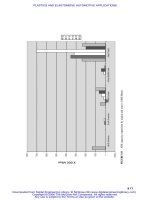
FIG. 14 DIAGRAM FOR ASSESSMENT OF WELDING CAPACITY OF THERMOPLASTIC
S. ARROW DIRECTION
SHOWS INCREASE IN WELDABILITY BY THE INDIRECT METHOD. LDPE, LOW-DENSITY POLYETHYL
ENE; HDPE,
HIGH-DENSITY POLYETHYLENE; PA, POLYAMIDE; POM, POLYOXYMETHYLENE. SOURCE: REF 34
The key joining parameters of ultrasonic welding are the:
• AMPLITUDE OF VIBRATION DURING JOINING
• PRESSURE APPLIED DURING THE WELDING OPERATION
• JOINT GEOMETRY WHEN WELDING AMORPHOUS AND SEMICRYSTALLINE POLYMERS
• WELDING TIME AND ENERGY APPLIED DURING THE WELDING PROCESS
• TRIGGER PRESSURE/FORCE RELATIONSHIP (THE PRESSURE A
T WHICH ULTRASONIC
VIBRATIONS ARE INITIATED)
Applications. The success of ultrasonic welding lies in the fact that the process is very fast (welding times are
approximately 1 s), the equipment is compact, the process can be readily automated, and consistently acceptable weld
quality can be produced. Ultrasonic welding is commonly used to join components in the automotive, toy, domestic
appliance, and packaging industries. It is also the method of choice when welding many medical plastic components. The
only limitation is that large parts cannot be welded using this method.
References cited in this section
3. H. POTENTE AND P. MICHEL, THE STATE OF THE ART DEVELOPMENT T
RENDS IN THE
WELDING OF PLASTICS, PROC. 5TH ANNUAL NORTH AMERICAN WEL
DING RESEARCH
CONFERENCE, EWI AND AWS, 1989
10. A. BENATAR, MATERIAL CHARACTERISTICS FOR WELDING, PROC. 5TH ANNUAL NOR
TH
AMERICAN WELDING RESEARCH CONFERENCE, EWI AND AWS, 1989
26. V.K. STOKES, VIBRATION WELDING OF THERMOPLASTICS, PART I, POLYM. ENG. SCI.,
VOL
28, 1988, P 718-727
27. E. PECHA, D. CALINSKI, AND H. DIETER, PRODUCTION MACHINES AN
D TECHNICAL
APPLICATION FOR HOT PLATE AND VIBRATION WELDING, PROC. LNT. CONF. ADV
ANCES IN
JOINING PLASTICS AND COMPOSITES, THE WELDING INSTITUTE, CAMBRIDGE, 1991
28. V.K. STOKES, VIBRATION WELDING OF THERMOPLASTICS, PART II, POLYM. ENG. SCI.,
VOL
28, 1988, P 727-739
29. H. POTENTE AND H. KAISER, PROCESS VARIANT OF VIBRATION WELDI
NG WITH VARIABLE
WELDING PRESSURE, PROC. SPE 48TH ANTEC MEETING, SOCIETY OF PLASTICS EN
GINEERS,
1990, P 1762-1765
30. H. POTENTE AND M. UEBBING, COMPUTER AIDED LAYOUT OF THE VIBR
ATION WELDING
PROCESS, PROC. SPE 50TH ANTEC MEETING, 1992, SOCIETY OF PLASTICS ENGINEERS, P 888
31. M. CAKMAK AND K. KEUCHEL, U.S. PATENT 4,998,663, MARCH 1991
32. K. KEUCHEL AND M. CAKMAK, SPIN WELDING OF POLYPROPYLENE: CHA
RACTERIZATION
OF HEAT AFFECTED ZONE BY MICRO-BEAM WAXS TECHNIQUE, PROC. SPE 49TH ANTEC
MEETING, SOCIETY OF PLASTICS ENGINEERS, 1991, P 2477-2481
33. H. RAJARAMAN AND M. CAKMAK, THE EFFECT OF GLASS FIBER FILLERS ON
THE WELDING
BEHAVIOR OF POLY P-PHENYLENE SULFIDE, PROC. SPE 50TH ANTEC MEETING,
SOCIETY OF
PLASTICS ENGINEERS, 1992, P 896-899
34. H. POTENTE, ULTRASONIC WELDING PRINCIPLES AND THEORY, MAT. DES., VOL 5, 1984
35. T.B. ZACH, J. LEW, T.H. NORTH, AND R.T. WOODHAMS, "JOINING O
F HIGH STRENGTH
ORIENTED POLYPROPYLENE USING ELECTROMAGNETIC INDUCTION BONDI
NG AND
ULTRASONIC WELDING, MAT. SCI. TECH., VOL 5, 1989, P 281-287
36. J.S. WOLCOTT, DESIGNING PARTS FOR ULTRASONIC ASSEMBLY, PROC. SPE 48T
H ANTEC
MEETING, SOCIETY OF PLASTICS ENGINEERS, 1990, P 1829-1833
37. M.N. TOLUNAY, P.R. DAWSON, AND K.K. WANG, HEATING AND BONDIN
G MECHANISMS IN
ULTRASONIC WELDING OF THERMOPLASTICS, POLYM. ENG. SCI., VOL 23, 1983, P 726-733
38. G. HABERNICHT AND J. RITTER, ENERGY CONVERSION IN THE ULTRASONIC
WELDING OF
THERMOPLASTICS, KUNSTST. GER. PLAST., VOL 78, 1988, P 49-66
39. A. BENATAR AND T.G. GUTOWSKI, ULTRASONIC WELDING OF PEEK GRAPHITE APC-
2
COMPOSITES, POLYM. ENG. SCI., VOL 29 (NO. 23), 1989, P 1705-1721
40. N. TATEISHI, T.H. NORTH, AND R.T. WOODHAMS, ULTRASONIC WELDING USING TIE-
LAYERS, PART I: ANALYSIS OF PROCESS OPERATION, POLYM. ENG. SCI., VOL 32, 1992, P 600-
611
Welding of Plastics
Thomas H. North and Geetha Ramarathnam, University of Toronto
Electromagnetic Welding
The joining techniques described in this section include resistance, induction, dielectric, and microwave welding.
Resistance or Implant Welding
In this technique, a conducting wire or mesh is inserted at the interface between the parts being welded. This insert is
resistively heated by the passage of electric current (Fig. 15a), which melts the thermoplastic surrounding the insert,
forming a weld. It should be noted that the implant remains in the completed joint. Electrofusion is a technique whereby
the two ends of the pipe to be welded are inserted into a fitting/collar/coupler, the inside of which constitutes the heating
element (Ref 41, 42). The electric current that passes through the heating element promotes melting on the inside surface
of the fitting. Figure 15(b) shows a typical rectangular cross section of an electrofusion weld.
FIG. 15 (A) ELECTROFUSION (RESISTANCE) WELDING PROCESS. (B) ELECTROFUSION
WELDING PROCESS.
SOURCE: REF 42
The key joining parameters are the:
• APPLIED VOLTAGE AND APPLIED CURRENT, WHICH CAN BE AS HIGH AS 150 A
• CLAMPING PRESSURE DURING WELDING
• HEATING TIME
• AVOIDANCE OF CONTACTING SURFACE CONTAMINATION. BECAUSE MELT
FLOW IS
RESTRICTED DURING WELDING, IMPURITIES CAN BE TRAPPED AT THE
JOINT
INTERFACE, REDUCING THE STRENGTH OF THE WELD
Applications. The principal advantage of this joining method is that the equipment is relatively simple and portable.
Therefore, it can be used in on-site repair situations. The primary application area for electrofusion welding is the joining
of PE pipes with diameters less than 180 mm (7 in.), which are used for water transportation and natural gas distribution
(Ref 42).
Induction Welding
In this joining method, a layer of electromagnetic material in the form of a tape or a thin sheet is placed at the joint
interface. This insert material is heated using a high-frequency (2 to 10 MHz) inductive supply (Ref 43, 44). The
electromagnetic tapes contain conductive and ferromagnetic particles. The particle size, type, and concentration depend
on the application desired. The welding equipment comprises a high-frequency induction generator, a water-cooled
copper working coil, and press fixtures, which hold the polymer component so that it can be heated and loaded.
Heating results from eddy currents that are induced in the thermoplastic tape containing the ferromagnetic particles (Fig.
16), and energy generation is proportional to I
2
R. Heat generation during electromagnetic welding has been modeled,
particularly for cross-ply carbon fiber thermoplastic composites (Ref 45, 46).
FIG. 16 INDUCTION-HEATING MECHANISM. SOURCE: REF 5
The key joining parameters of this technique are the:
• COIL DESIGN, WHICH MUST BE CAREFULLY TAILORED TO SUIT THE END USE AND TO
PRODUCE A UNIFORM RADIO-FREQUENCY (RF) FIELD. A RANGE OF COIL DESIGNS
(SINGLE TURN, MULTITURN, HELICAL, BENT HAIRPIN, AND SO ON) ARE ALL POSSIBLE
• FREQUENCY AND POWER OUTPUT OF THE INDUCTION GENERATOR
• PARTICLE SIZE AND TYPE OF FILLER USED IN ELECTROMAGNETIC TAPE
MANUFACTURE
• DISTANCE BETWEEN THE INDUCTOR COILS AND THE BOND LINE
Applications. The principal advantage of this joining method is that it can handle components of complex geometry. The
process is also suitable for joining filled thermoplastic materials. The primary applications are in the automotive,
packaging, and appliance industries. In the medical field, electromagnetic induction welding has been employed for
joining PC blood oxygenators and arterial filter components.
The principal disadvantages of this joining process are the high cost of the equipment, the recurring costs associated with
the purchase of ferromagnetic-filled tapes, and the care that is required in the design and construction of the inductive
heating coils.
Dielectric Welding
In dielectric welding, the joint interface is subjected to much higher RF electrical energy. The process utilizes these major
components:
• A GENERATOR THAT PRODUCES A FREQUENCY RANGING FROM 13 TO 100 MHZ (27.12
MHZ IS TYPICAL) OF ELECTRICAL ENERGY AT AN OUTPUT OF 1 TO 25 KW
• A PRESS THAT CLAMPS THE SECTIONS TOGETHER DURING THE HEATING AND
SUBSEQUENT COOLING CYCLES
• A BRASS ELECTRODE OR DIE THAT IS MOUNTED ON AN ALUMINUM PLATE, WHICH
APPLIES THE ELECTRICAL ENERGY DIRECTLY TO THE PLASTIC (REF 47)
The key joining parameters of this process are the:
• DIELECTRIC LOSS FACTOR OF THE POLYMER OR THE PRESENCE OF
A DIPOLE,
BECAUSE A HIGH DIELECTRIC LOSS FACTOR INCREASES THE EFFECTIV
ENESS OF THE
JOINING OPERATION
• THICKNESS OF THE MATERIAL BEING JOINED
• OUTPUT POWER AND FREQUENCY OF THE GENERATOR EMPLOYED DURING WELDING
Applications. Dielectric welding is a fast, efficient joining method for sealing thin polymer films and sheet materials.
The equipment can be readily automated. However, the process can only be used on materials that have a high dielectric
loss factor, such as rigid or flexible PVC, ABS, and thermoplastic polyurethane materials. The principal application area
is in the packaging industry, where the process is used to join medical components, such as blood-pressure cuffs, medical
bags, rainwear, pool liners, and so on.
The primary disadvantage of this joining technique is that the initial equipment cost is high.
Microwave Joining
This joining technique depends on the heat produced by microwave-frequency radiation. The parts being joined are held
together under a slight pressure of 35 to 70 kPa (5 to 10 psi), and then the interface is irradiated by electromagnetic (EM)
radiation using well-focused horn antennas. In order to absorb EM energy, the polymer must contain polar groups. To
attain viable heating, either a nonconducting or a low-conductivity polymer may have to be doped with conducting
polymer or, as an alternative, an adhesive film that contains polar and/or electron-withdrawing groups can be placed at the
joint interface (Ref 48).
This joining method is relatively new and is still in the experimental stage. The experimental equipment (Ref 48) consists
of a magnetron tube that generates the microwave energy, a ferrite isolator that shields the magnetron and promotes the
efficient transmission of power with very little attenuation, a forward/reflected-power indicator that monitors the whole
system while it is in operation, a tuner that can be adjusted to minimize the reflected power and aid in the maximum
transfer of power from the source to the workpiece, a variable-coupling iris that optimizes and adjusts the power coupled
to the load, and, finally, an applicator that concentrates the microwave power at the joint region.
The key joining parameters of this process are the:
• MICROWAVE PROPERTIES OF THE MATERIAL, SUCH AS PERMITTIVITY A
ND
PERMEABILITY
• FREQUENCY AND ENERGY OF THE MICROWAVE SUPPLY
Applications. This welding technique is simple, fast, clean, and very efficient in terms of energy conversion.
Consequently, short welding times are involved. Dissimilar materials can be joined, and the use of a microwave-
absorbing adhesive will permit the repair of thermoset- or thermoplastic-based composite materials. This joining method
can be very useful for in-situ repairs of structures, especially on space vehicles and other aircraft.
References cited in this section
5. R.A. GRIMM, FUSION WELDING TECHNIQUES FOR PLASTICS, WELD. J., MARCH 1990, P 23-28
41. R.G. WILLIAMS, DEVELOPMENT OF A NOVEL ELECTROFUSION SYSTEM,"
GAS ENGINEERING
AND MANAGEMENT, VOL 26, 1986, P 43-46
42. J.R. ATKINSON AND I.M. WARD, THE JOINING OF BIAXIALLY ORIENTED POLYETHYLENE
PIPES, POLYM. ENG. SCI., VOL 29 (NO. 23), 1989, P 1638-1641
43. SM. CHOOKAZIAN, BONDING PLASTICS BY INDUCTION HEATING, SPE J., VOL 26, 1970, P 49-
53
44. A. LEATHERMAN, INDUCTION BONDING FINDS A NICHE IN AN EVOLVIN
G PLASTICS
INDUSTRY, PLAST. ENG., VOL 4, 1981, P 27-29
45. S.P. MOLNAR, CHARACTERIZATION AND CONTROL OF INDUCTION FUSIO
N BONDING OF
THERMOPLASTIC COMPOSITE,PROC. SPE 50TH ANTEC MEETING, SOCIETY OF PLASTICS
ENGINEERS, 1992, P 2102-2105
46. B.K. FINK, R.L. MCCULLOUGH, AND J.W. GILLESPIE JR., A LOCAL THEORY OF HEATING IN
CROSS-PLY CARBON FIBER THERMOPLASTIC COMPOSITES BY MAGNETIC INDUCT
ION,
POLYM. ENG. SCI., VOL 32, 1992, P 357-369
47. C.J. GIANNANDREA, RADIO FREQUENCY SEALING, MOD. PLAST., ENCYCLOPEDIA ISSUE,
OCT 1990, P 386-388
48. V.K. VARADAN AND V.V. VARADAN, MICROWAVE JOINING AND REPAIR
OF COMPOSITE
MATERIALS, POLYM. ENG. SCI., VOL 31, 1992, P 470-486
Welding of Plastics
Thomas H. North and Geetha Ramarathnam, University of Toronto
Evaluation of Welds
Because polymers are being used increasingly for semistructural and load-bearing applications, the testing of the welded
joints is important. The mechanical properties of welded plastics can be evaluated by performing standard destructive
tests, such as tensile, peel, wedge, and four-point bending. Of particular interest is the development of short-term tests
(Ref 49), where a hole is notched in the weld area (to create multiaxial stress). These short-term tests are for quality-
assurance purposes only.
For long-term applications, creep tests are much more favored. The measurement of thermal and residual stress has been
evaluated using the Moire interferometric method (Ref 50).
The microstructure of the weld zone can be examined using light microscopy, scanning electron microscopy (SEM), or x-
ray techniques (Ref 32, 51, 52). The microstructural examination of bonded regions is important because it allows:
• MEASUREMENT OF THE WELD ZONE AND HEAT-AFFECTED ZONE DIMENSIONS AND
THEIR UNIFORMITY ALONG THE WELD LINE
• EVALUATION OF THE DEVELOPMENT OF CRYSTALLINITY, ESPECIALLY THE
TRANSCRYSTALLINE REGION
• EVALUATION OF THE CHAIN ORIENTATION, ESPECIALLY PARALLEL TO THE BOND-
LINE REGION
• ESTIMATION OF THE FAILURE MODES OF MECHANICALLY TESTED WELD SECTIONS
• OPTIMIZATION OF WELDING CONDITIONS IN ORDER TO CONSISTENTLY PRODUCE
JOINTS OF OPTIMUM STRENGTH
Nondestructive evaluation (NDE) techniques for the detection of flaws in metal joints are well established. However, in
the case of plastic joints, much work is still required to optimize the application of NDE techniques (Ref 53).
References cited in this section
32. K. KEUCHEL AND M. CAKMAK, SPIN WELDING OF POLYPROPYLENE: CHA
RACTERIZATION
OF HEAT AFFECTED ZONE BY MICRO-BEAM WAXS TECHNIQUE, PROC. SPE 49TH ANTEC
MEETING, SOCIETY OF PLASTICS ENGINEERS, 1991, P 2477-2481
49. G. MENGES, E. SCHMACHTENBERG, AND R. KRAUSENBERGER, EIN SCHN
ELLER WEG ZUR
ERMITTLUNG DES LANGZEITVERHALTENS VON SCHWEIßNAHTEN, DVS BER., VOL 84, P 62-
65
50. J.B. PARK AND A. BENATAR, MOIRE INTERFEROMETRY MEASUREMENT O
F RESIDUAL
STRAINS IN IMPLANT RESISTANCE WELDING, PROC. SPE 50TH ANTEC MEETING,
SOCIETY
OF PLASTICS ENGINEERS, 1992, P 353-358
51. L.C. SAWYER AND D.T. GRUBB, IN POLYMER MICROSCOPY, CHAPMAN AND HALL, 1987
52. M.J. DAY AND M.F. GITTOS, "THE APPLICATION OF LIGHT MICROSCO
PY TO WELDED
JOINTS IN THERMOPLASTICS," REPORT 390, THE WELDING INSTITUTE, 1989
53. G.R. EDWARDS, NONDESTRUCTIVE EVALUATION OF WELDS IN PLASTICS,
PROC. 5TH
ANNUAL NORTH AMERICAN WELDING RESEARCH CONFERENCE, EWI AND AWS, 1989
Welding of Plastics
Thomas H. North and Geetha Ramarathnam, University of Toronto
References
General Review Articles on Joining and Welding of Polymers:
1. G. GEHARDSSON, THE WELDING OF PLASTICS, WELD. REV., FEB 1983, P 17-22
2. M.N. WATSON, R.M. RIVETT, AND K.I. JOHNSON, "PLASTICS
AN INDUSTRIAL AND
LITERATURE SURVEY OF JOINING TECHNIQUES," REPORT NO. 7846.01/
85/471.3, THE
WELDING INSTITUTE, ABINGTON, UK, 1986
3. H. POTENTE AND P. MICHEL, THE STATE OF THE ART DEVELOPMENT T
RENDS IN THE
WELDING OF PLASTICS, PROC. 5TH ANNUAL NORTH AMERICAN WELDING RESEAR
CH
CONFERENCE, EWI AND AWS, 1989
4. V.K. STOKES, JOINING METHODS FOR PLASTICS AND PLASTIC COMPOS
ITES: AN
OVERVIEW, POLYM. ENG. SCI., VOL 29 (NO. 19), 1989, P 1310-1324
5. R.A. GRIMM, FUSION WELDING TECHNIQUES FOR PLASTICS, WELD. J., MARCH 1990, P 23-28
6. G. MENGES, THE JOINING OF PLASTICS AND THEIR COMPOSITES,
PROC. LNT. CONF.
ADVANCES IN JOINING NEWER STRUCTURAL MATERIALS, IIW (MONTREAL), P 33-63
Adhesive Bonding:
7. A.J. KINLOCH, ADHESION AND ADHESIVES, CHAPMAN AND HALL, 1987, P 101
Mechanical Fastening:
8. D. CHANT, JOINING TECHNOLOGY FOR THERMOPLASTIC COMPOSITE STR
UCTURES IN
AEROSPACE APPLICATIONS, PROC. INT. CONF. ADVANCES IN JOINING PLA
STICS AND
COMPOSITES, THE WELDING INSTITUTE, CAMBRIDGE, 1991
Welding Mechanisms and Weldability of Thermoplastics:
9. S.S. VOYUTSKII, AUTOHESION AND ADHESION OF HIGH POLYMERS, WI
LEY
INTERSCIENCE, 1963
10. A. BENATAR, MATERIAL CHARACTERISTICS FOR WELDING, PROC. 5TH ANNUAL NOR
TH
AMERICAN WELDING RESEARCH CONFERENCE, EWI AND AWS, 1989
11. R.P. WOOL, B L. YUAN, AND O.J. MCGAREL, POLYM. ENG. SCI., VOL 29 (NO. 19), 19
89, P
1340-1367
Solvent Welding:
12. W.V. TITOW, CHAPTER 12, SOLVENT WELDING OF PLASTICS,
APPLIED SCIENCE
PUBLISHERS, LONDON, P 181-196
13. M. LICATA AND E. HAAG, SOLVENT WELDING WITH POLYCARBONATE,
PROC. SPE 44TH
ANTEC MEETING, SOCIETY OF PLASTICS ENGINEERS, 1986, P 1092-1094
Heated-Tool Welding:
14. K. GABLER AND H. POTENTE, WELDABILITY OF DISSIMILAR THERMOPLASTICS
EXPERIMENTS IN HEATED TOOL WELDING, J. ADHES., VOL 11, 1980, P 145-163
15. H. POTENTE AND P. TAPPE, SCALE-UP LAWS IN HEATED TOOL BUTT WELDING OF H
DPE
AND PP, POLYM. ENG. SCI., VOL 29 (NO. 23), 1989, P 1642-1648
16. H. POTENTE AND J. NATROP, COMPUTER AIDED OPTIMIZATION OF THE
PARAMETERS OF
HEATED TOOL BUTT WELDING, POLYM. ENG. SCI., VOL 29 (NO. 23), 1989, P 1649-1654
17. A.J. POSLINSKI AND V.K. STOKES, ANALYSIS OF THE HOT-TOOL WELDING PROCESS
,
PROC. SPE 50TH ANTEC MEETING, 1992, SOCIETY OF PLASTICS ENGINEERS, P 1228-1233
Hot-Gas Welding:
18. H. GUMBLETON, HOT GAS WELDING OF THERMOPLASTICS AN INTRODUCTION,
JOIN.
MAT., VOL 5, 1989, P 215-218
19. "RECOMMENDED PRACTICES FOR JOINING PLASTIC PIPING," DOCUMENT XVI-322-78-
E,
IIW
Extrusion Welding:
20. P. MICHEL, "AN ANALYSIS OF THE EXTRUSION WELDING PROCESS," POLYM. ENG. SCI.,
VOL 29 (NO. 19), 1989, P 1376-1382
21. M. GEHDE AND G.W. EHRENSTEIN, STRUCTURAL AND MECHANICAL PROP
ERTIES OF
OPTIMIZED EXTRUSION WELDS, POLYM. ENG. SCI., VOL 31 (NO. 7), 1991, P 495-501
Infrared Welding:
22. H. SWARTZ AND J.L. SWARTZ, FOCUSSED INFRARED A NEW JOINING TECHNO
LOGY FOR
HIGH PERFORMANCE THERMOPLASTICS AND COMPOSITE PARTS,
PROC. 5TH ANNUAL
NORTH AMERICAN WELDING RESEARCH CONFERENCE, EWI AND AWS, 1989
23. H. POTENTE, P. MICHEL, AND M. HEIL, INFRARED RADIATION WELDING: A METHOD FOR
WELDING HIGH TEMPERATURE RESISTANT THERMOPLASTICS, PROC. SPE 49TH ANTEC
MEETING, SOCIETY OF PLASTICS ENGINEERS, 1991, P 2502-2504
Laser Welding:
24. W.W. DULEY, IN LASER PROCESSING AND ANALYSIS OF MATERIALS, PLENUM PRESS, 1983
25. W.W. DULEY AND R.E. MUELLER, CO
2
LASER WELDING OF POLYMERS, POLYM. ENG. SCI.,
VOL 32 (NO. 9), 1992, P 582-585
Vibration Welding:
26. V.K. STOKES, VIBRATION WELDING OF THERMOPLASTICS, PART I, POLYM. ENG. SCI.,
VOL
28, 1988, P 718-727
27. E. PECHA, D. CALINSKI, AND H. DIETER, PRODUCTION MACHINES AND TECHNICAL
APPLICATION FOR HOT PLATE AND VIBRATION WELDING, PROC. LNT. CONF. ADV
ANCES
IN JOINING PLASTICS AND COMPOSITES, THE WELDING INSTITUTE, CAMBRIDGE, 1991
28. V.K. STOKES, VIBRATION WELDING OF THERMOPLASTICS, PART II, POLYM. ENG. SCI.,
VOL
28, 1988, P 727-739
29. H. POTENTE AND H. KAISER, PROCESS VARIANT OF VIBRATION WELDI
NG WITH
VARIABLE WELDING PRESSURE, PROC. SPE 48TH ANTEC MEETING, SOCIETY OF PLASTICS
ENGINEERS, 1990, P 1762-1765
30. H. POTENTE AND M. UEBBING, COMPUTER AIDED LAYOUT OF THE VIBRATION WELDI
NG
PROCESS, PROC. SPE 50TH ANTEC MEETING, 1992, SOCIETY OF PLASTICS ENGINEERS, P 888
Spin Welding: